Table of Contents
Advertisement
Quick Links
Advertisement
Table of Contents

Related Manuals for Swann AMI Oxytrace


Summary of Contents for Swann AMI Oxytrace
- Page 1 AMI Oxytrace AMI Oxytrace QED Version 6.20 and higher A-96.250.531 / 300617...
- Page 2 SWAN representative, or the manufacturer: SWAN ANALYTISCHE INSTRUMENTE AG Studbachstrasse 13 8340 Hinwil Switzerland Internet: www.swan.ch E-mail: support@swan.ch Document Status Monitor AMI Oxytrace QED Operator’s Manual Title: A-96.250.531 Revision Issue Jan. 2008 First Edition Nov. 2008 Including AMI Oxytrace QED...
-
Page 3: Table Of Contents
Single Components ........2.4.1 AMI Oxytrace Transmitter....... - Page 4 AMI Oxytrace QED Operation ......... . .
-
Page 5: A-96.250.531 / 300617
AMI Oxytrace QED Default Values........ -
Page 6: Safety Instructions
AMI Oxytrace QED Safety Instructions AMI Oxytrace QED - Operator’s Manual This document describes the main steps for instrument setup, oper- ation and maintenance. Safety Instructions General The instructions included in this section explain the potential risks associated with instrument operation and provide important safety practices designed to minimize these risks. -
Page 7: Warning Notices
AMI Oxytrace QED Safety Instructions 1.1. Warning Notices The symbols used for safety-related notices have the following sig- nificance: DANGER Your life or physical wellbeing are in serious danger if such warnings are ignored. Follow the prevention instructions carefully. - Page 8 AMI Oxytrace QED Safety Instructions Warning Signs The importance of the warning signs in this manual. Electrical shock hazard Corrosive Harmful to health Flammable Warning general Attention general A-96.250.531 / 300617...
-
Page 9: General Safety Regulations
AMI Oxytrace QED Safety Instructions 1.2. General Safety Regulations Legal The user is responsible for proper system operation. All precautions must be followed to ensure safe operation Requirements of the instrument. Spare Parts Use only official SWAN spare parts and disposables. If other parts are used during the normal warranty period, the manufacturer’s... -
Page 10: Product Description
2.1. Description of the System Application AMI Oxytrace is used to measure low levels of oxygen in high-puri- ty water. Especially in power plant water cycles (e.g. feedwater), a very low level of oxygen is needed to prevent corrosion. Measuring... - Page 11 AMI Oxytrace QED Product Description Faraday For AMI Oxytrace QED only. Verification When a direct current is passed through water by means of two electrodes, electrolysis of the liquid takes place, according to the laws of Michael Faraday. Water is converted to molecular oxygen and hydrogen.
- Page 12 AMI Oxytrace QED Product Description Signal Two signal outputs programmable for measured values (freely scaleable, linear or bilinear) or as continuous control output (control Outputs parameters programmable). Current loop: 0/4–20 mA 510 Maximal burden: Third signal output available as an option.
- Page 13 AMI Oxytrace QED Product Description Fluidics AMI Oxytrace Swansensor oxygen combined with QV-flow PMMA OTG flow cell. The sample flows via sample inlet [G] through the flow regulating valve [D], where the flow rate can be adjusted. Then the sample flows into the measuring cell [C] were the Oxygen concentration and temperature of the sample is measured.
- Page 14 AMI Oxytrace QED Product Description Fluidics AMI Oxytrace QED Swansensor oxygen combined with QV-flow PMMA OTG flow cell. The sample flows via sample inlet [H] through the flow regulating valve [E], where the flow rate can be adjusted. Then the sample flows through the faraday electrode [D] into the measuring cell [C] were the Oxygen concentration of the sample is measured.
-
Page 15: Technical Data
AMI Oxytrace QED Product Description 2.2. Technical Data Power Supply Voltage: 100–240 VAC (± 10%) 50/60 Hz (± 5%) or 24 VDC (± 10%) Power consumption: max. 30 VA Electronics Aluminium with a protection degree of IP 66 / NEMA 4X... - Page 16 AMI Oxytrace QED Product Description Dimensions Panel: Stainless steel (Oxytrace and 280x850x150 mm Oxytrace QED) Mounting hole distance 254x824 Screws: 8 mm diameter Weight: 12.0 kg 280 mm/ 11” 254 mm/ 10” AMI Oxytrace A-96.250.531 / 300617...
-
Page 17: Instrument Overview
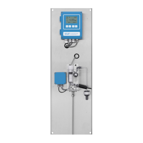
AMI Oxytrace QED Product Description 2.3. Instrument Overview AMI Oxytrace Panel Flow regulating valve AMI Transmitter Sample outlet Oxygen sensor Drain funnel Flow sensor Sample inlet Flow cell A-96.250.531 / 300617... - Page 18 AMI Oxytrace QED Product Description AMI Oxytrace QED Panel Flow cell AMI Transmitter Flow regulating valve Faraday control unit Faraday electrode Oxygen sensor Drain funnel Sample outlet Sample inlet Flow sensor A-96.250.531 / 300617...
-
Page 19: Single Components
AMI Oxytrace QED Product Description 2.4. Single Components 2.4.1 AMI Oxytrace Transmitter Electronic transmitter and controller for oxygen measurement. 18.5 Dimensions Width: 140 mm Height: 180 mm Depth: 70 mm Weight: 1.5 kg Specifications Electronics case: Cast aluminum Protection degree:... -
Page 20: Sensor Oxytrace G
AMI Oxytrace QED Product Description 2.4.2 Sensor OXYTRACE G Sensor for the measurement of dissolved oxygen in ultra pure wa- ter. Precise oxygen measuring cell with integrated temperature sensor and guard electrode for faster initial response time after maintenance. Technical data :... -
Page 21: Qv-Flow Pmma Otg
AMI Oxytrace QED Product Description 2.4.3 QV-Flow PMMA OTG Flow cell Flow cell made of acrylic glass with integrated flow sensor. Sample temp. max. 45 °C Inlet pressure max. 1 bar Outlet pressure Pressure free Sample flow 6–25 l/h Process con- Swagelok connection for 1/4”... -
Page 22: B-Flow Ss316L Otg
AMI Oxytrace QED Product Description 2.4.4 B-Flow SS316L OTG Flow cell B-Flow SS316L OTG is made of stainless steel without flow sensor and can be used for higher operating pressures and temperatures. Operating temp. -10 to + 130 °C Sensor max. -
Page 23: Installation
AMI Oxytrace QED Installation Installation The first part of this chapter describes the preparing and placing of the system in position for use. The second part describes the wiring and the properties of the signal outputs and relay. Restrictions If exposed to weather, install a cover to protect the instrument from insolation and precipitation. -
Page 24: Mounting Of Instrument Panel
AMI Oxytrace QED Installation Turn-on Switch on power. First, the analyzer performs a self test, displays the firmware ver- power sion and then starts normal operation Run-in Period Leave the sensor at the air. The sensor has to run-in for at least 30 min, better 1 h. -
Page 25: Connecting Sample Inlet And Outlet
AMI Oxytrace QED Installation 3.3. Connecting Sample Inlet and Outlet 3.3.1 Swagelok Fitting Stainless Steel at Sample Inlet Preparation Cut the tube to length and deburr it. The tube must be straight and free from blemishes for approximately 1,5 x tube diameter from the end. -
Page 26: Fep Tube At Sample Outlet
2 Remove the transport protection cap [B]. 3 Clean the Swansensor Oxytrace G [C] with water. 4 Install the Swansensor Oxytrace G into the flow cell 5 Connect the sensor cable to the transmitter, see Electrical Con- nection Diagram AMI Oxytrace, p. A-96.250.531 / 300617... -
Page 27: Electrical Connections
AMI Oxytrace QED Installation 3.5. Electrical Connections WARNING Risk of electrical shock. Do not perform any work on electrical components if the trans- mitter is switched on. Failure to follow safety instructions could result in serious injury or death. Always turn off AC power before manipulating electric parts. - Page 28 AMI Oxytrace QED Installation WARNING External Voltage. External supplied devices connected to relay 1 or 2 or to the alarm relay can cause electrical shocks Make sure that the devices connected to the following con- tacts are disconnected from the power before resuming in- stallation.
-
Page 29: Electrical Connection Diagram Ami Oxytrace
AMI Oxytrace QED Installation 3.5.1 Electrical Connection Diagram AMI Oxytrace CAUTION Use only the terminals shown in this diagram, and only for the mentioned purpose. Use of any other terminals will cause short circuits with possible corresponding consequences to material and personnel. -
Page 30: Electrical Connection Diagram Ami Oxytrace Qed
AMI Oxytrace QED Installation 3.5.2 Electrical Connection Diagram AMI Oxytrace QED CAUTION Use only the terminals shown in this diagram, and only for the mentioned purpose. Use of any other terminals will cause short circuits with possible corresponding consequences to material and personnel. -
Page 31: Power Supply
Mains cable to comply with standards IEC 60227 or IEC 60245; flammable rating FV1 Mains equipped with an external switch or circuit-breaker – near the instrument – easily accessible to the operator – marked as interrupter for AMI Oxytrace QED A-96.250.531 / 300617... -
Page 32: Input
AMI Oxytrace QED Installation 3.6. Input NOTICE: Use only potential-free (dry) contacts. The total resistance (sum of cable resistance and resistance of the relay contact) must be less than 50 Ω. Terminals 16 and 42 If the signal output is set to hold, the measurement is interrupted if input is active. -
Page 33: Relay 1 And 2
AMI Oxytrace QED Installation 3.7.2 Relay 1 and 2 NOTICE: Max. load 1 A/250 VAC Relay 1 and 2 can be configured as normally open or as normally closed. Standard for both relays is normally open. To configure a Relay as normally closed, set the jumper in the upper position. - Page 34 AMI Oxytrace QED Installation CAUTION Risk of damage of the relays in the AMI Transmitter due to heavy inductive load. Heavy inductive or directly controlled loads (solenoid valves, dosing pumps) may destroy the relay contacts. To switch inductive loads > 0.1 A use an AMI relay box avail- able as an option or suitable external power relays.
-
Page 35: Signal Outputs
AMI Oxytrace QED Installation 3.8. Signal Outputs 3.8.1 Signal output 1 and 2 (current outputs) NOTICE: Max. burden 510 Ω. If signals are sent to two different receivers, use signal isolator (loop isolator). Signal output 1: Terminals 14 (+) and 13 (-) -
Page 36: Signal Output 3
AMI Oxytrace QED Installation 3.9.1 Signal Output 3 Terminal 38 (+) and 37 (-). Requires the additional board for the third signal output 0/4–20 mA PCB. The third signal output can be operated as a current source or as a current sink (switchable via switch [A]). For detailed infor- mation see the corresponding installation instruction. -
Page 37: Hart Interface
AMI Oxytrace QED Installation 3.9.3 HART Interface Terminals 38 (+) and 37 (-). The HART interface PCB allows for communication via the HART protocol. For detailed information, consult the HART manual. HART Interface PCB 3.9.4 USB Interface The USB Interface is used to store Logger data and for Firmware up load. -
Page 38: Instrument Setup
AMI Oxytrace QED Instrument Setup Instrument Setup 4.1. Establish Sample Flow 1 Open the flow regulating valve [A] and wait until the flow cell is completely filled. 2 Switch on power. 3 Adjust the sample flow to 8–25 l/h. 4.2. -
Page 39: Operation
AMI Oxytrace QED Operation Operation 5.1. Keys Exit Enter to exit a menu or command (rejecting any changes) to move back to the previous menu level to move DOWN in a menu list and to decrease digits to move UP in a menu list and to increase digits... -
Page 40: Display
AMI Oxytrace QED Operation 5.2. Display 15:20:18 0.15 23 °C 12 l/h normal operation HOLD input closed or cal delay: Instrument on hold (shows status of signal outputs). input closed: control/limit is interrupted (shows status of signal outputs). ERROR Error... -
Page 41: Software Structure
AMI Oxytrace QED Operation 5.3. Software Structure Main Menu Messages Diagnostics Maintenance Operation Installation Menu Messages 1 Messages Reveals pending errors as well as an event history Pending Errors (time and state of events that have occurred at an Maintenance List earlier point of time). -
Page 42: Changing Parameters And Values
AMI Oxytrace QED Operation 5.4. Changing Parameters and values Changing The following example shows how to change the logger interval: parameters 1 Select the parameter you want to Sensors Logger 5.1.2 4.4.1 change. Sensor type FOME Log interval 30 min 2 Press [Enter] Disinf. -
Page 43: Maintenance
Maintenance Maintenance frequency depends strongly on the water quality. The AMI Oxytrace QED is designed for determination of low level of dis- solved oxygen in high purity water. It is not suitable for the measurement of dissolved oxygen in waste water. -
Page 44: Maintenance Of The Oxygen Sensor
AMI Oxytrace QED Maintenance 6.3. Maintenance of the Oxygen Sensor WARNING Etching liquid The electrolyte is alkaline and caustic. It contains less than 1% of potassium hydroxide. Do not ingest. Wear protective goggles and gloves during handling. Avoid contact with clothes. - Page 45 AMI Oxytrace QED Maintenance Swansensor Oxytrace G Thread Groove Guard electrode Anode Measuring head Cathode Sensor cap with membrane 3 Unscrew and remove the sensor cap [H] from the Swansensor Oxytrace G [A]. 4 Empty the remaining electrolyte. 5 Refill the sensor cap with fresh electrolyte.
-
Page 46: Clean Swansensor Oxytrace G And Flow Cell
AMI Oxytrace QED Maintenance 6.3.2 Clean Swansensor Oxytrace G and Flow Cell Depending on the water quality, the Swansensor Oxytrace G and the flow cell will necessitate a cleaning. Before cleaning, stop operation as described in Stop of Operation for Maintenance, p. -
Page 47: Maintenance Of The Faraday Electrode
AMI Oxytrace QED Maintenance 6.4. Maintenance of the Faraday electrode Fixing sleeve Electrode body Washer O-ring Inner electrode O-ring Hollow electrode 1 Switch off the instrument and close the flow regulating valve. 2 Open the faraday control unit. 3 Disconnect and remove the cable from the faraday control unit. - Page 48 AMI Oxytrace QED Maintenance 8 Clean the inner electrode (E) with a tissue and the hollow elec- trode with a pipe cleaner. The electrode surfaces should be shining metallic after cleaning. Use a polishing detergent or a small amount of toothpaste.
-
Page 49: Calibration
AMI Oxytrace QED Maintenance 6.5. Calibration The sensing part of the sensor must not be in direct contact with water! In the wet flow cell, the atmosphere will be saturated with water va- por. This atmosphere will produce the most accurate calibration re- sults. - Page 50 AMI Oxytrace QED Maintenance 7 Place the electrode slightly tilted Calibration 3.1.5 into the flow cell, so that the sensor Place the electrode into cap rests on the rim for the O-ring. the wet flow cell at a slightly tilted angle.
-
Page 51: Zero-Verification
AMI Oxytrace QED Maintenance 6.6. Zero-Verification Swansensor Oxytrace G for the measurement of low oxygen con- tent (< 1 ppb). 1 Calibrate the sensor according to chapter Calibration, p. 2 Prepare a 5%-sodium sulfite solution with demineralized water. 3 Put the electrode into the sodium sulfite solution afterwards. As- sure that there are no air bubbles in front of the sensor. -
Page 52: Faraday Verification
AMI Oxytrace QED Maintenance 6.7. Faraday Verification The Faraday verification works only for oxygen concentrations be- low 200 ppb. If automatic Faraday verification is enabled, a periodic check of the system is performed. A manual verification can be started for test purposes. -
Page 53: Quality Assurance Of The Instrument
Every SWAN on-line instrument is equipped with integrated, auton- omous quality assurance functions to survey the plausibility of each measurement. For the AMI Oxytrace/AMI Oxytrace QED these are: continuous monitoring of sample flow continuous monitoring of the temperature inside the transmit- ter case ... -
Page 54: Activate Swan Quality Assurance Procedure
AMI Oxytrace QED Maintenance max. deviation max. deviation min. inspection Quality Level temperature [°C] result [%] interval 0: Off 0.5 °C 10 % 1: Trend annual 0.4 °C 2: Standard quarterly 0.3 °C 3: Crucial monthly 0 - 2°C 0 - 20%... -
Page 55: Pre-Test
Remaining operating time on display minimum 20 hours. – Sensor is in working condition. On-line instrument: Monitor AMI Oxytrace QED – Good order and condition; Flow cell free of particles, Sensor surface free of deposits. - Page 56 Reference flow cell T-fitting On-line flow cell 1 Stop sample flow to the monitor AMI Oxytrace by closing the appropriate valve, e.g. back pressure regulator, sample prepa- ration or flow regulating valve at flow cell. 2 Connect sample line of the monitor AMI Oxytrace [A] with the sample inlet of the reference instrument AMI INSPECTOR Oxy- gen [B].
-
Page 57: Carry Out Comparison Measurement
6.8.4 Carry out comparison measurement The comparison measurement is menu driven. Start by selecting Quality Assurance in menu 3.5 of the monitor AMI Oxytrace. 1 Navigate to menu Maintenance /Quality Assurance. 2 Press [Enter]. 3 Follow the dialog on the Display. -
Page 58: Completion Of The Measurement
Maintenance 6.8.5 Completion of the measurement 1 Stop the sample flow to the AMI Oxytrace QED by closing the appropriate valve, e.g. back pressure regulator, sample prepa- ration or flow regulating valve at flow cell again. 2 Close flow regulating valve of the AMI Inspector. -
Page 59: Replacing Fuses
AMI Oxytrace QED Maintenance 6.9. Replacing Fuses WARNING External Voltage. External supplied devices connected to relay 1 or 2 or to the alarm relay can cause electrical shocks. Make sure that the devices connected to the following con- tacts are disconnected from the power before continuing the installation. -
Page 60: Longer Stop Of Operation
AMI Oxytrace QED Maintenance 6.10. Longer Stop of Operation 1 Shut off power of the instrument. 2 Stop sample flow. 3 Remove the Swansensor Oxytrace G. 4 Clean the sensor with a soft tissue and rinse it with water after- wards. -
Page 61: Error List
AMI Oxytrace QED Error List Error List Error Non-fatal Error. Indicates an alarm if a programmed value is ex- ceeded. Such Errors are marked E0xx (bold and black). Fatal Error (blinking symbol) Control of dosing devices is interrupted. The indicated measured values are possibly incorrect. - Page 62 AMI Oxytrace QED Error List Error Description Corrective action – check process E001 Oxygen Alarm high – check programmed value, 5.3.1.1.1, S. 79 – check process E002 Oxygen Alarm low – check programmed value, 5.3.1.1.25, S. 79 – check process...
- Page 63 AMI Oxytrace QED Error List Error Description Corrective action – check case/environment temperature E013 Case Temp. high – check programmed value, 5.3.1.5.1, S. 80 – check case/environment temperature E014 Case Temp. low – check programmed value, 5.3.1.5.2, S. 80 – check control device or programming in...
- Page 64 AMI Oxytrace QED Error List Error Description Corrective action – call service E032 Wrong Frontend – none, normal status E033 Power-on – none, normal status E034 Power-down – Refill electrolyte, see Electrolyte E065 Electrolyte depleted exchange, S. 42 A-96.250.531 / 300617...
-
Page 65: Program Overview
AMI Oxytrace QED Program Overview Program Overview For explanations about each parameter of the menus see Program List and Explanations, S. Menu 1 Messages informs about pending errors and mainte- nance tasks and shows the error history. Password protection possible. -
Page 66: Diagnostics (Main Menu 2)
AMI Oxytrace QED Program Overview 8.2. Diagnostics (Main Menu 2) Identification Desig. AMI Oxytrace * Menu numbers 2.1* Version 6.20-06/16 Factory Test Instrument 2.1.3.1* 2.1.3* Motherboard Front End Operating Time Years / Days / Hours / Minutes / Seconds 2.1.4.1* 2.1.4*... -
Page 67: Maintenance (Main Menu 3)
AMI Oxytrace QED Program Overview 8.3. Maintenance (Main Menu 3) Calibration Calibration 3.1.5 * Menu numbers 3.1* Service Electrolyte Last filling 3.2* 3.2.1* Remaining amount Remaining time New Filling 3.2.1.5* Faraday Verification Current Value 3.2.2 Faraday Conc. Progress Simulation Alarm Relay 3.2.1*... -
Page 68: Operation (Main Menu 4)
AMI Oxytrace QED Program Overview 8.4. Operation (Main Menu 4) Sensors Filter Time Const. 4.1.1* * Menu numbers 4.1* Hold after Cal. 4.1.2* Faraday Parameter Mode 4.1.3.1* 4.1.3* Interval 4.1.3.20* Delay 4.1.3.3* Signal Outputs 4.1.3.4* Output/Control 4.1.3.5* Relay Contacts Alarm Relay... -
Page 69: Installation (Main Menu 5)
AMI Oxytrace QED Program Overview 8.5. Installation (Main Menu 5) Sensors Miscellaneous Flow 5.1.1.1* * Menu numbers 5.1* 5.1.1* Offset 5.1.1.2* Quality Assurance Level 5.1.2.1* 5.1.2* Signal Outputs Signal Output 1/2 Parameter 5.2.1.1 - 5.2.2.1* 5.2* 5.2.1* - 5.2.2* Current Loop 5.2.1.2 - 5.2.2.2*... - Page 70 AMI Oxytrace QED Program Overview Miscellaneous Language 5.4.1* * Menu numbers 5.4* Set defaults 5.4.2* Load Firmware 5.4.3* Password Messages 5.4.4.1* 5.4.4* Maintenance 5.4.4.2* Operation 5.4.4.3* Installation 5.4.4.4* Sample ID 5.4.5* Line Break Detection 5.4.6* Interface Protocol 5.5.1* (only with RS485 5.5*...
-
Page 71: Program List And Explanations
AMI Oxytrace QED Program List and Explanations Program List and Explanations 1 Messages 1.1 Pending Errors 1.1.5 Provides the list of active errors with their status (active, acknowl- edged). If an active error is acknowledged, the alarm relay is active again. - Page 72 AMI Oxytrace QED Program List and Explanations 2.2.1.4 Cal. History Review the diagnostic values of the last calibration of the oxygen sensor. Max. 64 data records are memorized. Number: Calibration counter. Date, Time: Date and time of the calibration. Sat. Current: Saturation current at that time of calibration.
-
Page 73: Maintenance
AMI Oxytrace QED Program List and Explanations 3 Maintenance 3.1 Calibration 3.1.1 Start a calibration and follow the instructions on the screen. Dis- played values are saturation in % and the saturation current in mA. The indication bar shows the progress. Detailed explanation see Calibration, p. - Page 74 AMI Oxytrace QED Program List and Explanations 3.3 Simulation In this menu the following relays and signal outputs can be tested: Alarm relay Relay 1 and 2 Signal output 1 and 2 Signal output 3 (if option is installed)
-
Page 75: Operation
AMI Oxytrace QED Program List and Explanations 4 Operation 4.1 Sensors 4.1.1 Filter Time Constant: Used to damp noisy signals. The higher the filter time constant, the slower the system reacts to changes of the measured value. Range: 5–300 Sec 4.1.2... -
Page 76: Installation
AMI Oxytrace QED Program List and Explanations 4.2 Relay Contacts Relay Contacts, p. 30 4.3 Logger The instrument is equipped with an internal logger. The data can be copied to the USB stick installed in the transmitter. The logger can save approx. 1500 data records. The Records con- sists of: Date, time, alarms, measuring values, raw values, case temperature, flow. - Page 77 AMI Oxytrace QED Program List and Explanations 5.2 Signal Outputs NOTICE: The navigation in the menu <Signal Output 1> and <Signal Output 2> is equal. For reason of simplicity only the menu numbers of Signal Output 1 are used in the following.
- Page 78 AMI Oxytrace QED Program List and Explanations [mA] 0 / 4 1’000 10’000 X Measured value (logarithmic) 5.2.1.40 Scaling: Enter beginning and end point (Range low & high) of the linear or logarithmic scale. In addition, the midpoint for the bilinear scale.
- Page 79 AMI Oxytrace QED Program List and Explanations As control Signal outputs can be used for driving control units. We distinguish different kinds of controls: output P-controller: The controller action is proportional to the devia- tion from the setpoint. The controller is characterized by the P-Band.
- Page 80 AMI Oxytrace QED Program List and Explanations Setpoint: User defined precess value for the selected parameter. P-Band: Range below (upwards control) or above (downwards con- trol) the set-point, within which the dosing intensity is reduced from 100% to 0% to reach the set-point without overshooting.
- Page 81 AMI Oxytrace QED Program List and Explanations 5.3 Relay Contacts 5.3.1 Alarm Relay: The alarm relay is used as cumulative error indicator. Under normal operating conditions the contact is active. The contact is inactive at: Power loss Detection of system faults like defective sensors or electronic parts ...
- Page 82 AMI Oxytrace QED Program List and Explanations 5.3.1.2.2 Alarm High: If the measuring values rises above the programmed value E009 will be issued. Range: 12–50 l/h 5.3.1.2.35 Alarm Low: If the measuring values falls below the programmed value E010 will be issued.
- Page 83 AMI Oxytrace QED Program List and Explanations 5.3.2 and 5.3.3 Relay 1 and 2: The function of relay contacts 1 or 2 are defined by the user NOTICE: The navigation in the menu <Relay 1> and <Relay 2> is equal. For reason of simplicity only the menu numbers of Relay 1 are used in the following.
- Page 84 AMI Oxytrace QED Program List and Explanations 5.3.2.50 Delay: Duration, the activation of the alarm relay is retarded after the measuring value has risen above/fallen below the programmed alarm. Range. 0–600 Sec 5.3.2.1 Function = Control upwards/downwards The relays may be used to drive control units such as solenoid valves, membrane dosing pumps or motor valves.
- Page 85 AMI Oxytrace QED Program List and Explanations 5.3.2.32.31 Control Parameters: Range for each Parameter same as 5.2.1.43, p. 78 Actuator = Motor valve Dosing is controlled by the position of a motor driven mixing valve. 5.3.2.32.22 Run time: Time needed to open a completely closed valve Range: 5–300 Sec.
- Page 86 AMI Oxytrace QED Program List and Explanations 5.3.2.6 Signal Outputs: Select operating mode of the signal output: Cont.: Signal outputs continue to issue the measured value. Hold: Signal outputs hold the last valid measured value. Measurement is interrupted. Errors, except fatal errors, are not issued.
- Page 87 AMI Oxytrace QED Program List and Explanations 5.3.2.342 Calendar: 5.3.2.342.1 Start time: The programmed start time is valid for each of the pro- grammed days. To set the start time see 5.3.2.341, p. Range: 00:00:00–23:59:59 5.3.2.342.2 Monday: Possible settings, on or off 5.3.2.342.8...
- Page 88 AMI Oxytrace QED Program List and Explanations 5.3.4.3 Output/Control: (relay or signal output): Cont.: Controller continues normally. Hold: Controller continues on the last valid value. Off: Controller is switched off. 5.3.4.4 Fault: No message is issued in pending error list and the alarm relay does not close when input is active.
- Page 89 AMI Oxytrace QED Program List and Explanations 5.4 Miscellaneous 5.4.1 Language: Set the desired language. Available settings: German /English/French/Spanish 5.4.2 Set defaults: Reset the instrument to factory default values in three different ways: Calibration: Sets calibration values back to default. All other values are kept in memory.
- Page 90 AMI Oxytrace QED Program List and Explanations 5.5 Interface Select one of the following communication protocols. Depending on your selection, different parameters must be defined. 5.5.1 Protocol: Profibus 5.5.20 Range: 0–126 Device address: 5.5.30 Range: Analyzer; Manufacturer; Multivariable ID-Nr.: 5.5.40...
-
Page 91: Material Safety Data Sheets
AMI Oxytrace QED Material Safety Data sheets Material Safety Data sheets 10.1. Reagents Catalogue No.: 102751.10 Product name: Filling solution 1ALK Part of: A-87.290.060 Download The current Material Safety Data Sheets (MSDS) for the above list- ed Reagents are available for downloading at www.swan.ch. -
Page 92: Default Values
AMI Oxytrace QED Default Values Default Values Operation: Sensors: Filter Time Const.:..............10 Sec Hold after Cal.:..............300 Sec Faraday Parameter: Mode: ................Interval Interval:................3 hours Delay .................. 60 sec Signal Outputs................ hold Output/Control ............... hold Alarm Relay ..............same as in Installation Relay 1/2 .............. - Page 93 AMI Oxytrace QED Default Values Sample Temp., Alarm High: ............. 50 °C Sample Temp., Alarm Low: ............0 °C Alarm Saturation; Alarm high..........120 % Alarm Saturation; Alarm low ............ 0.0 % Alarm Saturation; Hysteresis ............2 % Alarm Saturation; Delay............5 Sec Case temp.
- Page 94 AMI Oxytrace QED Default Values Signal output:................cont Output/Control: ................cont Input: Active ................when closed Signal Outputs ................hold Output/Control ................off Fault....................no Delay..................10 Sec Miscellaneous Language:................English Set default:..................no Load firmware: ................no Password: ............for all modes 0000 Sample ID: ............... - - - - - - - - Line break detection ..............no...
-
Page 95: Index
AMI Oxytrace QED Index Index ..Alarm Relay Mounting requirements ....Cable thicknesses P-Band . -
Page 96: Notes
AMI Oxytrace QED Notes Notes A-96.250.531 / 300617... - Page 97 AMI Oxytrace QED Notes A-96.250.531 / 300617...
- Page 98 AMI Oxytrace QED SWAN is represented worldwide by subsidiary companies and distributors. cooperates with independent representatives all over the world. SWAN Products Analytical Instruments for: High Purity Water Feedwater, Steam and Condensate Potable Water Pool and Sanitary Water Cooling Water...