
Related Manuals for ABB PVS800-57B


Summary of Contents for ABB PVS800-57B
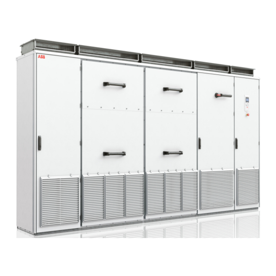
- Page 1 — ABB SOLAR INVERTERS PVS800-57B central inverters Commissioning and maintenance manual...
- Page 2 — List of related manuals Hardware manuals and guides Code (English) PVS800-57B central inverters hardware manual 3AXD50000048300 PVS800-57B central inverters commissioning and maintenance manual 3AXD50000048331 Firmware manuals and guides PVS800-57B central inverters firmware manual 3AXD50000048332 Option manuals and guides ACS-AP-x Assistant control panels user’s manual 3AUA0000085685 Start-up and maintenance PC tool Drive composer user’s manual...
- Page 3 Commissioning and maintenance manual PVS800-57B central inverters Table of contents 1. Safety instructions 4. Mechanical installation 5. Electrical installation 7. Start-up and operation 2018 ABB Oy. All Rights Reserved. 3AXD50000048331 Rev A EFFECTIVE: 2018-06-25...
-
Page 5: Table Of Contents
Table of contents 1. Safety instructions Contents of this chapter ..........9 Use of warnings . - Page 6 Preventing the recirculation of hot air ........36 Ventilation duct at the air outlet of the cabinet .
- Page 7 9. Maintenance Contents of this chapter ..........59 Maintenance intervals .
-
Page 9: Safety Instructions
Safety instructions 9 Safety instructions Contents of this chapter This chapter contains the safety instructions which you must obey when you install and operate the inverter and do maintenance on the inverter. Obey these safety instructions to prevent injury or death, or damage to the equipment. Use of warnings Warnings tell you about conditions which can cause injury or death, or damage to the equipment. -
Page 10: Installation And Maintenance Safety
10 Safety instructions Installation and maintenance safety Electrical safety These warnings are for all personnel who do work on the inverter, its input and output cables, the transformer or photovoltaic generator. WARNING! Obey these instructions to prevent injury or death, or damage to the equipment. - Page 11 Refer to standard IEC/EN 62109, 5.2.5. or IEC62477-1, 4.4.4.3.3. Electric welding WARNING! Do not fasten the cabinet by electric welding. ABB does not assume any liability for damages caused by electric welding as the welding circuit can damage electronic circuits in the cabinet.
-
Page 12: Performing Electrical Work
12 Safety instructions Performing electrical work These precautions are for all personnel who do work on the inverter, its input and output cables, the transformer or the photovoltaic generator system. WARNING! Obey these instructions to prevent injury or death, or damage to the equipment. - Page 13 Safety instructions 13 6. Install temporary grounding as required by the local regulations. Connect the AC and DC busbars (in both DC sections) to the PE with a temporary grounding tool. Temporary grounding cables must be dimensioned to withstand the prospective current of the system for time duration until upstream protection device clears the fault current.
-
Page 14: General Safety
Use caution when you move an inverter power module. Do not tilt the module. The module is heavy. It can topple over if you handle it carelessly. • Obey the instructions in the PVS800-57B central inverters commissioning and maintenance manual (3AXD50000048331 [EN]). •... -
Page 15: Safe Start-Up And Operation
• If the Start switch is in the ON position, the Inverter enable signal is active, and the Start command is active, the inverterconverter starts immediately after a fault reset. For more information, see the PVS800-57B central inverters Firmware manual. - Page 16 16 Safety instructions...
-
Page 17: Introduction To The Manual
The flowchart refers to sections in this manual and in other manuals. Applicability This manual is applicable to PVS800-57B central inverters. Target audience This manual is intended for persons who plan the installation of, install, commission, use and service the inverter. -
Page 18: Contents Of The Manual
The instructions and technical data which concern optional components are marked with option codes, for example, +K475. The options included in the inverter can be identified from the type designation label. For information on the type designation labels, refer to the PVS800-57B central inverters hardware manual (3AXD50000048300 [EN]). -
Page 19: Quick Installation, Commissioning And Operation Flowchart
Task Refer to Plan the installation. Technical data and Planning the electrical installation in the PVS800-57B central inverters Do a check of the ambient conditions, ratings, required hardware manual (3AXD50000048300 [EN]) cooling air flow, input and output power connection, compatibility with the solar generator and other technical Option manual (if optional equipment is included) data. -
Page 20: Terms And Abbreviations
Programmable logic controller PSL2 Protocol used in optical fiber communication inside ABB drives and inverters Photovoltaic Inverter power module Residual current device... - Page 21 Introduction to the manual 21 Term/Abbreviation Explanation SCADA Supervisory control and data acquisition Solar array Group of parallel-connected solar strings Solar array junction Device that connects outputs of multiple solar source circuits (strings) into a combined output circuit or circuits Solar cell Device that converts light directly into electricity by the photovoltaic effect Solar generator...
- Page 22 22 Introduction to the manual...
-
Page 23: Storing, Lifting And Transporting
Storing, lifting and transporting 23 Storing, lifting and transporting Contents of this chapter This chapter tells you how to store, lift and move the inverter. Moving the inverter You can move the inverter with a crane from the lifting beams on the roof or with a fork-lift from the base of the inverter. -
Page 24: Storing The Inverter
24 Storing, lifting and transporting Storing the inverter • To prevent damage to the inverter, keep it in the protective packaging. • Store the inverter in the upright position. Do not put it on its side or back. • To prevent condensation in the inverter, store it indoors in a dry (heated) warehouse. •... -
Page 25: Lifting The Inverter In The Shipping Package
Storing, lifting and transporting 25 Lifting the inverter in the shipping package With a crane • Lift the inverter in its shipping packaging. If you remove the packaging, protect the inverter from scratches and dents. • Make sure that the slings have sufficient loading capacity. •... -
Page 26: With A Forklift Truck
26 Storing, lifting and transporting With a forklift truck • Lift the inverter in its shipping packaging. If you remove the packaging, protect the inverter from scratches and dents. • Lift the inverter from the lifting holes on the base of the inverter. •... -
Page 27: Moving The Crate With A Forklift
Storing, lifting and transporting 27 Moving the crate with a forklift ... -
Page 28: Transporting The Inverter
28 Storing, lifting and transporting Transporting the inverter WARNING! Keep the transportation height as low as possible. Make sure that the total height of the transportation is not above the maximum allowed height for the planned route. Do not use too much force with cargo straps even when the inverter is in its shipping package. -
Page 29: Mechanical Installation
Mechanical installation 29 Mechanical installation Contents of this chapter This chapter describes the mechanical installation of the inverter. Obey all local regulations. Safety Refer to Safety instructions on page 9. For instructions on how to move the inverter, refer to Storing, lifting and transporting page 23. -
Page 30: Examining The Delivery
Loose items: floor mounting brackets, screw kits, module extraction/installation ramp Make sure that the delivery has no signs of damage. Mark and record any damage carefully and contact the local ABB representative immediately. Repair any damaged paint. Manuals and other loose parts are delivered inside the inverter. Before you start to install or operate the inverter, read the type designation label of the inverter to make sure that the delivery is correct. -
Page 31: Moving The Unpacked Inverter Cabinet
Mechanical installation 31 Moving the unpacked inverter cabinet Lifting the cabinet with a crane Lift the inverter cabinet using its lifting beams. You can remove the lifting beams after the cabinet is in its final position. If you remove the lifting beams, seal their mounting holes to retain the degree of protection. - Page 32 32 Mechanical installation Moving the cabinet on its back Support the cabinet from below alongside the cubicle seams. Cabinet back panel Support Final placement of the cabinet Move the cabinet into its final position with a slate bar (spud bar). Put a piece of wood between the edge of the cabinet and the bar to protect the cabinet frame.
-
Page 33: Fastening The Cabinet To The Floor And Wall Or Roof
Mechanical installation 33 Fastening the cabinet to the floor and wall or roof General rules • Install the inverter in an upright vertical position. • You can install the cabinet with its back against a wall (a), or back-to-back with another unit (b). •... -
Page 34: Fastening Methods
34 Mechanical installation Fastening methods Fasten the cabinet to the floor with the clamps included along the edge of the cabinet bottom. Clamping Floor clamping Clamp dimensions Insert the clamps into the twin slots along the front and rear edges of the cabinet frame body and fasten them to the floor with a M12 bolt. -
Page 35: Miscellaneous
The air inlets of the installation space must supply a sufficient volume of cooling air. For the minimum air flow values, refer to PVS800-57B central inverters hardware manual (3AXD50000048300 [EN]). WARNING! Make sure that the incoming air is sufficiently clean. If not, dust goes into the cabinet. -
Page 36: Preventing The Recirculation Of Hot Air
36 Mechanical installation Preventing the recirculation of hot air To prevent hot air recirculation outside the inverter, make sure that the exhaust air flows away from the air inlets. Make sure that the hot air from the inverter module cabinet does not flow into the adjacent cabinets. - Page 37 = 0.5 • • v = 0.5 • 1.1 • 5.5 = 17 Pa The required pressure in the exit air duct is then, 1.5…2 • 17 Pa = 26…34 Pa, below the pressure in the room. For more information: Contact ABB.
- Page 38 38 Mechanical installation...
-
Page 39: Electrical Installation
Electrical installation 39 Electrical installation Contents of this chapter This chapter describes the electrical installation of the inverter. Insulation test Inverter The inverter is tested for insulation at the factory. Do not perform voltage tolerance or insulation resistance tests on any part of the inverter. AC output cables ... -
Page 40: Routing The Cables
40 Electrical installation Routing the cables When you route the cables: • Install the DC power, AC power and control cables on separate routes. • Make sure that the metallic cable trays are electrically bonded to each other and to the ground. -
Page 41: Connecting The Power Cables
Electrical installation 41 Connecting the power cables Connection diagram Inverter Transformer Solar array junction box. If you use shielded cable, 360-degree grounding is recommended at the cabinet entry. Ground the other end of the input cable shield or PE conductor at the transformer. 3), 4) If you use shielded cable (which is recommended) and the conductivity of the shield is <... -
Page 42: Connection Diagram Of A Four-Conductor System
42 Electrical installation Connection diagram of a four-conductor system Arrange the cables as shown to get a current distribution that is as equal as possible. L2 L3 L3 L1 L1 L2 Connect single-core cables without concentric protective shielding (armor) as shown. Inverter Transformer WARNING! Ground all conductive cable supports, cable clamps and individual... -
Page 43: Dc Input Cable Connection Procedure
Electrical installation 43 DC input cable connection procedure Refer to the dimension drawings in the PVS800-57B central inverters hardware manual (3AXD50000048300 [EN]). 1. Remove the shroud from the input power terminals. 2. Put the cable(s) into the inside of the cabinet. -
Page 44: Ac Output Cable Connection Procedure
44 Electrical installation AC output cable connection procedure Refer to the dimension drawings in the PVS800-57B central inverters hardware manual (3AXD50000048300 [EN]). 1. Remove the shroud from the output power terminals. 2. Put the cable(s) into the cabinet. 3. If it is a shielded cable, prepare the cable ends and do the 360° grounding at the cabinet entry. -
Page 45: Checking The Settings Of The Auxiliary Voltage Transformer
Electrical installation 45 Checking the settings of the auxiliary voltage transformer The connections of the optional auxiliary voltage transformer (T10) are made at the factory. Make sure that the connections agree with the selected option code (+G396, +G397). If not, change the connection wire to the correct voltage terminal. +AUX-F12:2 +AUX-F12:4 +AUX-F12:6... -
Page 46: Connecting The Control Cables
12 User AI3 4–20 mA You can freely configure the I/O signals with different fault names and reactions. Refer to the PVS800-57B central inverters firmware manual (3AXD50000048332 [EN]). Connection procedure 360-degree grounding at the cabinet lead-through for the control cables: Make sure that a proper environmental seal remains after the installation. -
Page 47: Fast Power Off Circuit
Electrical installation 47 a) Cable shield b) Grounding wire c) Shielded twisted pair d) Copper foil Connecting the cables to the I/O terminals Connect the conductors to the appropriate terminals of the I/O section (refer to Default I/O connection diagram on page 46). -
Page 48: Connecting A Pc
48 Electrical installation Connecting a PC You can connect a PC (for example, using the Drive composer PC tool) to the inverter as follows: 1. Connect an ACS-AP-I control panel to the inverter control unit either with an Ethernet cable, or by inserting the control panel into the panel holder (if present). WARNING! Do not connect the PC directly to the control panel ethernet connector of the inverter. -
Page 49: Installing Fieldbus Adapter Modules
Electrical installation 49 Installing fieldbus adapter modules Note: Pay attention to the free space required by the cabling or terminals coming to the option modules. 1. Disconnect the inverter from the supply, lock out the disconnecting device, and ensure by measuring that there is no voltage present. 2. - Page 50 50 Electrical installation...
-
Page 51: Installation Checklist
Installation checklist 51 Installation checklist Contents of this chapter This chapter contains a list for checking the mechanical and electrical installation of the inverter. Warnings WARNING! Obey the instructions in chapter Safety instructions. If you ignore them, injury or death, or damage to the equipment can occur. -
Page 52: Checklist
The AC line voltage matches the nominal output voltage of the inverter. The AC transformer is suitable for use with the inverter (refer to the PVS800-57B central inverters hardware manual (3AXD50000048300 [EN])). The insulation of the assembly is sufficient (refer to Insulation test on page 39). -
Page 53: Start-Up And Operation
Make sure that the ambient conditions for start-up, temperature, humidity, altitude etc. are within the limits. Refer to PVS800-57B central inverters hardware manual (3AXD50000048300 [EN]). Set up the cabinet heater: Set the maximum temperature settings of the thermostats according to the schematic drawings. -
Page 54: Set Up The Insulation Monitoring Device
IT system. Make sure that the settings of the insulation monitoring device suit the installation and obey the local regulations. The trip limit is adjusted to 30 kohm at the factory. Refer to the PVS800-57B central inverters firmware manual (3AXD50000048332 [EN]). -
Page 55: Starting And Stopping The Inverter
Refer to the PVS800-57B central inverters firmware manual (3AXD50000048332 [EN]). Make sure that the DC voltage of the solar generator matches the parameter value. If the DC voltage is different from the parameter value, do not start the inverter. Contact ABB. Enable the inverter operation from parameter 189.1. - Page 56 56 Start-up and operation...
-
Page 57: Hardware Status
Hardware status Contents of this chapter This chapter describes the hardware signals that can be used to track faults. Refer to the PVS800-57B central inverters firmware manual for (3AXD50000048332 [EN]) warning and fault desciptions, status parameters, etc. LEDs The table tells the location, name, color and meaning of the LED indicators in the inverter. -
Page 58: Warning And Fault Messages
The input voltages (U2, V2 and W2) are more than 60 V. U1 > 60V Yellow The input voltages (U1, V1 and W1) are more than 60 V. Warning and fault messages Refer to the PVS800-57B central inverters firmware manual (3AXD50000048332[EN]). -
Page 59: Maintenance
Maintenance intervals If the inverter is installed in a suitable environment, it requires only minimum maintenance. The tables list the routine maintenance intervals recommended by ABB. The recommended maintenance intervals and component replacement are based on specified operational and enviromental conditions. ABB recommends annual inverter inspections to ensure the highest reliability and optimum performance. -
Page 60: Recommended Annual Maintenance Actions By The User
60 Maintenance Recommended annual maintenance actions by the user ABB recommends that you do these annual inspections to ensure the highest reliability and optimum performance of the inverter. Target / task Action Connections and environment Environment check Cabinet door filters IP41... -
Page 61: Maintenance Tasks
• Make sure that the installation environment of the inverter is according to the requirements. • Make sure that the inverters are installed according to ABB recommendations. For more information, refer to Mechanical installation on page and the PVS800-57B central inverters hardware manual (3AXD50000048300 [EN]). -
Page 62: Replacing The Cabinet Door Air Filters And Cleaning The Grilles
62 Maintenance Replacing the cabinet door air filters and cleaning the grilles WARNING! Obey the safety instructions, page 9. If you ignore the instructions, physical injury or death, or damage to the equipment can occur. 1. Stop the inverter and do the steps in Performing electrical work on page before you... -
Page 63: Fans
Maintenance 63 Fans Replacing the power module cooling fans WARNING! Obey the safety instructions on page 9. If you ignore the instructions, physical injury or death, or damage to the equipment can occur. 1. Before you start, stop the inverter and do the steps in Performing electrical work page 12. -
Page 64: Replacing The Power Module Board Compartment Fan
64 Maintenance Replacing the power module board compartment fan The R8i module has a fan to cool the circuit board compartment. You can access the fan from the front of the module. WARNING! Obey the safety instructions on page 9. If you ignore the instructions, physical injury or death, or damage to the equipment can occur. -
Page 65: Replacing The Lcl Filter Cooling Fans
Maintenance 65 Replacing the LCL filter cooling fans WARNING! Obey the safety instructions on page 9. If you ignore the instructions, physical injury or death, or damage to the equipment can occur. 1. Before you start, stop the inverter and do the steps in Performing electrical work page 12. -
Page 66: Replacing The Aux Cabinet Cooling Fan
66 Maintenance Replacing the AUX cabinet cooling fan WARNING! Obey the safety instructions on page 9. If you ignore the instructions, physical injury or death, or damage to the equipment can occur. 1. Before you start, stop the inverter and do the steps in Performing electrical work... -
Page 67: Replacing The Dc Cabinet Cooling Fans
Maintenance 67 Replacing the DC cabinet cooling fans The cooling fans of the DC cabinet are mounted on the protective metal panel in the cabinet. Depending on the number of DC inputs there are two or three cooling fans. WARNING! Obey the safety instructions on page 9. -
Page 68: Replacing The Ac Cabinet Cooling Fans
68 Maintenance Replacing the AC cabinet cooling fans The cooling fans of the AC cabinet are mounted on the protective metal panel in the cabinet. WARNING! Obey the safety instructions on page 9. If you ignore the instructions, physical injury or death, or damage to the equipment can occur. -
Page 69: Replacing The Inverter Power Module
Maintenance 69 Replacing the inverter power module The inverter power module can be replaced only by a technician who is authorized by ABB. Procedure Removing the inverter module(s) To allow more room for cabling work, the inverter modules can be removed completely instead of only the fan carriages. - Page 70 70 Maintenance...
- Page 71 Maintenance 71...
- Page 72 72 Maintenance...
-
Page 73: Heat Sink Cleaning
Maintenance 73 Re-installing the fan carriage of an inverter module (If the inverter module was removed completely instead of only the fan carriage, proceed to section Re-inserting the inverter module into the cubicle below.) The re-installation of the fan carriage is the removal procedure in reverse. See section Removing and reinstalling the fan carriage of an inverter module (page 112). -
Page 74: Memory Unit
74 Maintenance Memory unit When you replace the BCU-12 control unit, you can move the memory unit to the new control unit to keep the firmware and parameter settings. WARNING! Do not remove or insert the memory unit when the control unit is powered. -
Page 75: Dc Circuit Capacitors Reforming, Spare Modules, And Spare Capacitors
Maintenance 75 DC circuit capacitors reforming, spare modules, and spare capacitors If there are spare modules or separate spare DC circuit capacitors, ABB recommends that you reform the capacitors annually. See separate instructions on how to reform capacitors. - Page 76 76 Maintenance...
-
Page 77: Further Information
— Further information For more information on ABB products and services for solar applications, navigate to www.abb.com/solarinverters. - Page 78 © Copyright 2018 ABB. All rights reserved. Specifications subject to change without notice.