Table of Contents
Advertisement
Quick Links
Advertisement
Table of Contents

Related Manuals for ABB PVS-60-TL-US


Summary of Contents for ABB PVS-60-TL-US
- Page 1 ABB solar inverters Product manual PVS-60-TL-US...
- Page 2 THIS EQUIPMENT. Operators are required to read this manual and scrupulously follow the instructions given in it, since ABB cannot be held responsible for damage caused to people and/or things, or the equipment, if the conditions described below are not observed.
- Page 3 Other than under explicit contractual commit- ments, in no event shall ABB be responsible or liable for any loss or damage resulting from the use of this manual or the application of the equipment.
- Page 4 3 - Characteristics 4 - Lifting and transport 5 - Installation 6 - Instruments 7 - Operation 8 - Maintenance 9 - Attachments PVS-60-TL-US-Product manual EN-Rev A (M000047AG) EFFECTIVE 29/07/2019 © Copyright 2019 ABB. All Rights Reserved. - 4 -...
-
Page 5: Table Of Contents
able of Contents Table of Contents ............................5 afety and accident prevention ....................... 9 Safety information and instructions ....................9 Symbols and signs ..........................10 Installation and maintenance safety ....................11 General safety information ....................11 Environmental conditions and risks ..................11 Electrical and thermal safety ....................12 Clothing and protection of personnel ..................13 Residual risks ............................14 Table of residual risks ......................14... - Page 6 Characteristics of a photovoltaic generator ..................37 Strings and arrays .........................37 Description of the equipment ......................38 Operating diagram (example) ....................38 Mutual connection of multiple inverters ................39 Notes on the system sizing ....................39 Functionality and components of the equipment ................40 Communication connection diagrams ....................43 Communication interface ......................43 Ethernet bus connection .......................43 Topographic diagram of the equipment ................45...
- Page 7 Channel configuration examples ..................72 Independent channel configuration (default configuration) ..........73 Parallel channel configuration ....................73 DC input connection ..........................74 PVS-60-TL-US - PV input connection .................75 PVS-60-TL-S-US _ PV input connection ................76 PVS-60-TL-SC-US _ PV input connection ................77 Communication and control board ....................78 Connections to the communication and control board ..............79...
- Page 8 aintenance ........................... 136 General conditions ..........................136 Inverter total de-energization and safe access ................137 Operator and maintenance personnel skills/prerequisites ..........137 Clothing and protection of personnel ..................138 Safety equipment and tools ....................138 Inverter total de-energization and safe access procedure ..........139 Routine maintenance ......................148 Troubleshooting ..........................149 Internal Webserver and wireless communication troubleshooting ........149 Alarm Messages of the Inverter ..................151...
-
Page 9: Afety And Accident Prevention
The operators must read and comply with the technical information and instruction provided in the manual and in the attached documentation. ABB accepts no liability for failure to comply with the instructions for correct installation and cannot be held responsible for the upstream or downstream equipment. -
Page 10: Symbols And Signs
1 - Safety and accident prevention ymbols and signs In the manual and/or in some cases on the equipment, the danger or hazard zones are indicated with signs, labels, symbols or icons. Symbol Description General warning - Important safety information. Indicates a potentially hazardous situation which, if not avoided, could result in death or serious injury. -
Page 11: Installation And Maintenance Safety
1 - Safety and accident prevention nstallation and maintenance safety eneral safety information Do not proceed with installation if the integrity of the equipment is compromised. Do not use the equipment if you find any operating anomalies. Avoid temporary repairs. All repairs should be carried out using only genuine spare parts, which must be installed in accordance with their intended use. -
Page 12: Electrical And Thermal Safety
Do not perform insulation or voltage withstand tests on the inverter. ABB inverters must be earthed via the connection points marked with the protective earth symbol and using a cable with an appropriate conductor cross-section for the maximum ground fault current that the generating system might experience. -
Page 13: Clothing And Protection Of Personnel
1 - Safety and accident prevention lothing and protection of personnel NFPA - 70E, article 130.5 standard requires the equipment owner to field- label electrical equipment, to protect both in-house and contract workers from electric shock and arc flash, with labels containing the following information, : 1. -
Page 14: Residual Risks
1- Safety and accident prevention esidual risks Despite the warnings and safety systems, there are still some residual risks that cannot be eliminated. These risks are listed in the following table with some suggestions to prevent them. able of residual risks RISK ANALYSIS AND DESCRIPTION SUGGESTED REMEDY Noise pollution due to installation in unsuitable environments or where... -
Page 15: Introduction And General Information
ABB declares that the equipment complies with the provisions of law currently in force in the country of installation and has issued the corresponding declaration of conformity. -
Page 16: Scope And Target Audience
In addition to this user manual and maintenance you can consult (and download) the product documentation by visiting https://new.abb.com/ power-converters-inverters/solar. Part of the information given in this document is taken from the original supplier documents. This document contains only the information considered necessary for the use and routine maintenance of the equipment. -
Page 17: Application Area, General Conditions
2 - Introduction and general information pplication area, general conditions ABB shall not be liable for any damages whatsoever that may result from incorrect or careless operations. You may not use the equipment for a use that does not conform to that provided for in the field of use. -
Page 18: Haracteristics
Characteristics eneral conditions A description of the equipment characteristics is provided to identify its main components and specify the technical terminology used in the ma- nual. This chapter contains information about the models, details of the equipment, characteristics and technical data, overall dimensions and equipment identification. -
Page 19: Models And Range Of Equipment
DC terminal block for use with extenal combiner, DC disconnect switch, Conduit PVS-60-TL-US entry, DC and AC surge protection type II, 1 input channel (MPPT), Output conduit Input connection on the touch-safe fuse holder (5 pairs for each MPPT), Positive... -
Page 20: Identification Of The Equipment And Manufacturer
© Copyright 2019 Power-One Italy Spa. All rights reserved. Reproduction, use or disclosure to third parties without express written authority is strictly forbidden. © Copyright 2019 Power-One Italy Spa. All rights reserved. Reproduction, use or disclosure to third parties without express written authority is strictly forbidden. UL 1741 UL 1741 UL 1741 www.abb.com/solar CSA-C22.2 No. 107.1 www.abb.com/solar CSA-C22.2 No. 107.1 www.abb.com/solar CSA-C22.2 No. - Page 21 The officially required information is located on the regulatory label. The identification label is an accessory label which shows the information necessary for the identification and cha- racterisation of the inverter by ABB. In case you need to communicate with ABB about the inverter, the information from identification label are mandatory.
-
Page 22: Component Reference Designators
3 - Characteristics omponent reference designators Mounting bracket Cooling section Interposer board Locking brackets Lower support ALARM (multifuction relay) terminal block Inverter/bracket anchor points Communication and control board AUX (multifuction relay) terminal block Wiring box front door RSD board for (-R) version RS485-1/RS485-2 lines,R1ON/OFF and 5V terminal block LED panel... -
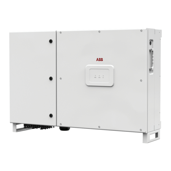
Page 23: Inverter (External View)
3 - Characteristics nverter (external view) Mounting braket Handle Locking brackets DC disconnect switch Inverter/bracket anchor points EGC connection point Wiring box front door DC opening for Trade 2” Size conduit LED panel AC opening for Trade 2” Size conduit Keylock Input quick fit connector CH1 Lifting ring... - Page 24 3 - Characteristics PVS-60-TL-S(-R)-US PVS-60-TL(-R)-US PVS-60-TL-SC(-R)-US PVS-60 PVS-60 PVS-50/60-TL PVS-50/60-TL-S INPUT OUTPUT AC PVS-60-TL-S(-R)-US PVS-50/60-TL-SX PVS-60-TL-SC(-R)-US INPUT PVS-50/60-TL-SX2 INPUT INPUT OUTPUT AC PVS-60-TL-SX-CN PVS-60-TL(-R)-US INPUT INPUT INPUT OUTPUT AC - 24 -...
-
Page 25: Inverter (Internal View)
3 - Characteristics nverter (internal view) DC disconnector switch Positive (+) side string fuses Fuse holder CH1 Communication and control board Protective earth connection point Fuse holder CH2 RSD board for (-R) version AC output screw terminal block Fuse holder CH3 DC overvoltage surge arresters DC input screw terminal block Plastic protection... -
Page 26: Communication Board
3 - Characteristics ommunication board Interposer board RS485-1 communication card housing Battery housing ALAM (multifuction relay) terminal block RS485-1 RJ45 connector SD card housing AUX (multifuction relay) terminal block RS485-2 RJ45 connector RSD board (only -R version) RS485-1 / RS485-2 lines, R1ON/OFF and RS485-2 120ohm termination switch Inverter data mem.card housing 5V terminal block... -
Page 27: Principal Inverter Components
3 - Characteristics rincipal inverter components • DC disconnect switch PVS-60-TL(-R)-US all versions Model: OTDC180U22 or equivalent DC disconnect switch Voltage Utilization category Current 1000Vdc DC-21B 150A (50A for each pole) • String fuses PVS-60-TL(-R)-US -S/-SC version The standard string protection fuses installed on the inverter have the following features: Voltage Rating... -
Page 28: Characteristics And Technical Data
3 - Characteristics haracteristics and technical data Table: Technical Data PVS-60-TL-US Input Absolute maximum input voltage (Vmax,abs) 1000 Vdc Input start-up voltage (Vstart) 420...700 V (Default 500V) Input operating interval (Vdcmin...Vdcmax) 0.7x Vstart... 950 V (min 360V) Rated input voltage (Vdcr) - Page 29 3 - Characteristics Table: Technical Data PVS-60-TL-US Communication 3x RS485, 2x Ethernet (RJ45), Embedded communication interfaces WLAN (IEEE802.11 b/g/n @ 2,4 GHz) User Interface 3 LEDs, Web User Interface, Mobile APP Communication protocol Modbus RTU/TCP (Sunspec compliant) Commissioning tool Web User Interface, Mobile APP Remote monitoring services Aurora Vision®...
-
Page 30: Tightening Torques
3 - Characteristics ightening torques To maintain the NEMA 4X protection rating of the system and for correct installation, the fol- lowing torques must be used: ft-lb Component 20 N-m 14.7 ft-lb DC input terminal block AWG-3/0 AWG (standard model) DC fuse holder 12 AWG-3/0 AWG (-s model) -
Page 31: Overall Dimensions
3 - Characteristics verall dimensions The overall dimensions (not including the mounting bracket ) are ex- pressed in millimetres and inches. 1160mm 285.5mm 45.6” 11.2” 268.5mm 30mm 410mm 685mm 30mm 10.5” 1.2” 16.1” 27” 1.2” 5mm / 0.2” PVS-60 INPUT OUTPUT AC - 31 -... -
Page 32: Mounting Bracket
3 - Characteristics ounting bracket The dimensions of the wall mounting bracket are expressed in milli- metres and inches. The diameter of holes in the bracket are 9mm/0.35”. 1160mm / 45.6” 16.8mm 40mm 270mm 270mm 270mm 270mm 40mm 6.6” 1.6” 10.6”... -
Page 33: Efficiency Curves
3 - Characteristics fficiency curves Graphs of the inverter efficiency for various input voltages are below: Efficiency curves 570Vdc 720Vdc 800Vdc 100% % rated Output Power The efficiency curves are approximate. - 33 -... -
Page 34: Automatic Power Limiting (Power Derating)
3 - Characteristics utomatic power limiting (Power Derating) When needed, the inverter automatically reduces the power fed to the grid. Power limiting may occur due to the following • Installation site ambient temperature is too hot (thermal derating) • Output power percentage set by user •... -
Page 35: Power Reduction Due To The Input Voltage
3 - Characteristics ower reduction due to the input voltage The reduction of the power supplied where the DC input voltage values are too high or too low is adjusted automatically. Output power Vs Input voltage * The curves on the graph, indi- cate how “All input powered”, are valid if the input voltages (of each input channel) are balanced. -
Page 36: P- Q Curve Capability
3 - Characteristics - Q curve capability Based on the country grid standard the P-Q capability curve can be reduced. PVS-60-TL - Rated output voltage (Un) 480Vac - Rated active power (Pn) 60kW - Nominal apparent power (Sn) 60kVA - Rated reactive power (Qn) 60kVAR - Cos -0 ... -
Page 37: Characteristics Of A Photovoltaic Generator
3 - Characteristics haracteristics of a photovoltaic generator A PV electric system consists of an assembly of photovoltaic modules that transform solar radiation into DC electrical energy and can be made up of: Strings: number of PV modules connected in series Array: group of strings connected in parallel trings and arrays The string technology was developed to significantly reduce the instal-... -
Page 38: Description Of The Equipment
(via a photovoltaic field, also called PV generator); in order to use it, it is transformed into “AC” alternate current. This conversion, known as inver- sion from DC to AC, is done in an efficient way by the ABB inverters, with- out using any rotary elements, rather only via static electronic systems. -
Page 39: Mutual Connection Of Multiple Inverters
A configuration program that can help to correctly size the photovoltaic system is available on the ABB website (http://stringsizer.abb.com). - 39 -... -
Page 40: Functionality And Components Of The Equipment
• Both vertical and horizontal installation • Wireless access to embedded user interfaces • ABB Installer for Solar Inverters APP for commissioning of inverters • Ethernet daisy chain enabled (supports both ethernet star/ring topology) • One RS485 line acting as master or slave •... - Page 41 Please contact the ABB tecnichal support for getting your own plant portfolio manager account (mainly for installers and plant administrators). Please get your Plant Viewer and Plant Viewer for Mobile by accessing the website www.auroravision.net and click on “Register with Plant Viewer”...
- Page 42 Sunspec standard. Please contact the ABB technical support or get access to Sunspec alliance website for further information on Modbus Sunspec products.
-
Page 43: Communication Connection Diagrams
(logging capability are already integrated into the inverter by default). Aurora Vision Plant Management platform is the ABB cloud solution allowing customer to remotely monitor and manage its own solar plants. Please refer to http://new.abb.com/power-... - Page 44 3 - Characteristics In order to improve the communication services and allow reaching of all the inverters in the chain also in presence of fault it is recommended to create a ring shape layout by connecting both the first and the last in- verters of the chain to the local Ethernet switch (as shown in the picture) Ethernet connection - Ring configuration Customer router...
-
Page 45: Topographic Diagram Of The Equipment
3 - Characteristics opographic diagram of the equipment The diagram summarises the internal structure of the inverter. The internal circuitry is with double stage conversion and therefore con- sists of: - DC/DC input converter (booster) - DC/AC output inverter The DC-DC converter and the DC-AC inverter both work at a high switching frequency and are therefore small and relatively light related to output power. - Page 46 3 - Characteristics - 46 -...
-
Page 47: Safety Devices
3 - Characteristics afety devices nti-Islanding In the event of a local grid outage by the electricity company, or when the equipment is switched off for maintenance operations, the inverter must be physically disconnected to ensure the protection of the people working on the grid, in accordance with the relevant national laws and regulations. -
Page 48: Ifting And Transport
During handling, do not make any sudden or fast movements that can create dangerous swinging. ifting ABB usually stores and protects individual components by suitable means to make their transport and subsequent handling easier, but as a rule, it is necessary to utilize the experience of specialized staff in change of loading and unloading the components. -
Page 49: Storage
4 - Lifting and transport torage If the package is stored correctly, it can withstand a maximum load of 6 stacked devices (divided into 3 pallets). DO NOT stack with equipment or products other than those indicated. eight of the modules of the equipment Table: Weights Weight Lifting points... -
Page 50: List Of Components Supplied
4 - Lifting and transport ist of components supplied Supplied with the inverter are all the components required to correctly install and connect the inverter Components available for all inverter models Mounting bracket Locking brackets + screws for the locking bracket mounting Connector for connection of the configurable relay Connector for connecting the communication and con-... -
Page 51: I Nstallation
Installation nstallation warnings The inverter must be corrrectly installed, in a suitable location, to operate properly and safely. Installers must know and understand applicable NEC requirements and any local codes for photovoltaic systems. Installers must know and understand OSHA and other applicable safety requirements, including lockout/tagout procedures. -
Page 52: Installation Planning
5 - Installation nstallation planning izing the ground cable(s) ABB inverters must be grounded at the protective earth (PE) connection point terminal. Size the cable(s) in accordance with NEC and any local codes. The conductor must be large enought to handle the maximum ground fault current that the PV system might experience. -
Page 53: Choice Of Grid Output Connection Type (Ac Side)
5 - Installation hoice of grid output connection type (AC side) The medium voltage trasformer, i.e. the grid (distribution system), must face the inverter as a grounded WYE, whose Neutral may or may not be brought to the inverter: 1. Lines R,S,T, Neutral + GND (“four-wire”) The DIP switch S1 must be set for “4 WIRES”... -
Page 54: Ac Overcurrent Protection
5 - Installation AC overcurrent protection AC output overcurrent protection is not provided in the inverter; it is the responsibility of the end user to provide overcurrent protection for the AC output circuit. To reduce the risk of fire, connect only to a dedicated circuit provided with overcurrent protection in accordance with the NEC (ANSI/NFPA 70): PVS-60.0-TL-US... -
Page 55: String Fuse Sizing (-S / -Sc Models)
5 - Installation tring Fuse sizing (-S / -SC models) The correct sizing of the positive side (+) and negative side (-) string fuses to be used to protect from “return currents” is very important because it reduces the risk of fire and damage to the PV array. PVS-60-TL-S(-R)-US A “return current”... - Page 56 - increase in the effective irradiation of the installation area - Increase in the Isc based on high PV module temperature - fuse thermal derating - maximum return current of the PV modules 15A fuses are available from ABB: Code Description Quantity...
-
Page 57: Installation Procedure For Quick-Fit Connectors
The model of connectors installed on your inverter must be matched by the same model of the respective corresponding parts to be used (check the corresponding part on the manufacturer's website or with ABB). Using mating parts that are not compliant with the quick fit connector models on the inverter could cause serious damage to the unit and lead to invalidation of the warranty. - Page 58 5 - Installation - Insert the crimped terminal contact into the insulator body of the con- nector, until you hear the click indicating that the terminal is engaged inside the connector. Click - Firmly tighten the cable gland using the relevant tool to finish the ope- ration.
-
Page 59: Installation Site And Position
- If possible, install at eye level so that the LEDs can be easily seen 50cm - Install at a height that takes account of the weight of the equipment 5° MAX - All installations over 6500’ (2,000 meters) must be assessed by ABB PVS-60 PVS-60 Technical Sales to determine the proper datasheet derating - Install vertically or horizontally (i.e. - Page 60 5 - Installation - Multiple inverters can also be placed in a staggered arrangement. PVS-60 Minimum clearances for staggered arrangements include the width of inverter plus additional allowances for inverters arranged above or PVS-60 PVS-60 PVS-60 below 50cm PVS-60 PVS-60 30cm 20cm PVS-60...
-
Page 61: Wireless Signal Environmental Checks
5 - Installation ireless signal environmental checks The inverter can be commissioned and monitored using the wireless communication channel. The WLAN board of the inverter uses radio waves to transmit and receive data, it is therefore important to assess this factor in order to have optimal installation. •... -
Page 62: Installations Above 2000 Meters
5 - Installation nstallations above 2000 meters On account of the rarefaction of the air (at high altitudes), particular conditions may occur that should be considered when choosing the place of installation: • Less efficient cooling and therefore a greater likelihood of the device going into derating because of high internal temperatures. -
Page 63: Mounting Of The Inverter On The Bracket
5 - Installation ounting of the inverter on the bracket The mounting bracket can be used to install the inverter on a vertical or horizontal support. • Position the bracket per- fectly level on the support and use it as drilling template. •... - Page 64 5 - Installation Lift the inverter up to the bracket • using the handles , or ano- ther appropriate lifting device. The inverter is pre-equipped with lower support which allow it to be temporarily put vertically on the floor to make it easier the lifting.
- Page 65 5 - Installation • Install the 4 fixing braket on the 4 locking brakets attachment point (one for each corner of the inverter) using the supplied 8 screws. • Remove the protective co- ver from the connector of the wireless antenna located on the left side of the inverter.
-
Page 66: Installing The Ground Cable(S)
5 - Installation nstalling the ground cable(s) Connect the ground cables of the DC side to the equipment grounding conductor terminal (EGC) EGC connection point accept a ring cable lug, suitable for a M6 size threaded insert (torque to 11Nm/8ft-lb) Attach the AC side ground cable to the protective earth (PE) connection point The protective earth (PE) connection point accept a ring cable lug, suitable... -
Page 67: Grid Output Connection (Ac Side)
5 - Installation rid output connection (AC side) The medium voltage trasformer, i.e. the grid (distribution system), must face the inverter as a grounded WYE, whose Neutral may or may not be brought to the inverter: - Lines R,S,T, Neutral + GND (“four-wire”) OR - Lines R,S,T+ GND (“three-wire,”... -
Page 68: Operations Preliminary To The Connection Of The Pv Generator
5 - Installation perations preliminary to the connection of the PV generator onfirm the PV arrays have no ground leakage All the following activities must be performed wearing the PPE and using appropriate measuring devices. Measure the voltage present between positive and negative terminal of each string with respect to ground. - Page 69 5 - Installation Behavior of a system with leakage All the following activities must be performed wearing the PPE and using appropriate measuring devices. If the voltage measured between one of the two terminals and ground does not discharge to 0V, but stabilizes on a non-zero value, there is ground leakage from the PV array.
-
Page 70: Measuring The Insulation Resistance Of The Pv Array
5 - Installation easuring the insulation resistance of the PV array. The operator must always use the personal protective equipment (PPE) required by the laws of the country of destination and whatever is provided by their employer. To measure the insulation resistance (from ground ) in the PV array, the two terminals of the PV array must be short circuited (using a suitably sized short). -
Page 71: Independent Or Parallel Input Channels Configuration
5 - Installation ndependent or parallel input channels configuration The inverter equipped with DC wiring box -S and -SC versions have th- ree input channels (thus benefiting from three trackers for MPPT maxi- mum power point tracking) which work independently of one another, which can be paralleled by leveraging a single MPPT. -
Page 72: Channel Configuration Examples
5 - Installation Channel configuration examples PV generator characteristics MPPT configuration Notes The photovoltaic generator consists A NECESSARY condition so that the of strings having a different number three MPPTs can be used in independent of modules in series from each other. mode is for the photovoltaic generator The photovoltaic generator consists MPPT configuration... -
Page 73: Independent Channel Configuration (Default Configuration)
2. In the dedicated section of the internal webserver “Setup section > Setup DC side > Input mode” In the standard model (PVS-60-TL-US) is available only one input channel and therefore not possible to set the inputs as independent arallel channel configuration In the -S and -SC inverter models, the configuration of the input channels (MPPT) can be set in parallel. -
Page 74: Dc Input Connection
5 - Installation C input connection After having carried out preliminary checks and therefore having verified that there are no problems in the photovoltaic system, and the channel configuration has been selected (parallel or independent) you may connect the inputs to the inverter. According to the system configuration, check the correct setting of the channels to independent or in parallel mode. -
Page 75: Pvs-60-Tl-Us - Pv Input Connection
5 - Installation VS-60-TL-US - PV input connection - Confirm that PV array equipment ground wire(s) is connected to the equipment ground connection point (labelled “EGC”). - Confirm the DC cables are 4AWG - 3/0AWG, copper or aluminum. - Connect PV array to the the DC input terminal block (+ and -). -
Page 76: Pvs-60-Tl-S-Us _ Pv Input Connection
5 - Installation VS-60-TL-S-US _ PV input connection - Confirm that PV array equipment ground wire(s) is connected to the equipment ground connection point (labelled “EGC”). -S models have fuse holders for each individual string conductor pair. Fuses are sized for single-string currents only. - Confirm that strings are not paralleled in the PV array. -
Page 77: Pvs-60-Tl-Sc-Us _ Pv Input Connection
INPUT INPUT Refer to the document “String inverter – Product Manual appendix” available at www.abb. com/solarinverters to know the brand and the model of the quick fit connector. Depending on the model of the connector of the own inverter, it is necessary to use the same model and the... -
Page 78: Communication And Control Board
5 - Installation ommunication and control board Silkscreen Reference Symbol Interposer board ALARM (multifunction relay) terminal block AUX (multifunction relay) terminal block RS485-1 and RS485-2 lines, R1 ON/OFF and R2 ON/OFF (remote ON/ OFF) and 5V auxiliary lines terminal block RS485-1 line 120Ohm termination resistor switch RS485-1 communication card housing RS485-1 line connection on RJ45 connector... -
Page 79: Connections To The Communication And Control Board
5 - Installation onnections to the communication and control board The communication and control signals are connected to the communication and control board inside the DC wiring box or directly to the connectors on the outside of the inverter. In particular, on the left side of the inverter, there are 3 different configurations depending on the type of inverter chosen: PVS-60-TL(-R)-US: This inverter model equipped with 5 holes on which... -
Page 80: Ethernet Connection Configuration
For further information on the Ethernet connection refer to the Local Area Network standard IEEE802.3 Please refer to Aurora Vision documents available on ABB website for further information how to get an Aurora Vision account for remotely monitoring and managing the installed solar assets. -
Page 81: Ethernet Connection
5 - Installation thernet connection The connection of the ethernet communication cable must be made on the specific connectors located on the interposer board (vertically positioned on the communication and control board )inside the wiring box. If the inverters of the plant need to be connected in daisy chain or ring configuration use both connectors. - Page 82 5 - Installation Proceed as follows to install the cable on the inverter: 5. Remove the cap from the ethernet connector installed on the inverter. 6. Connect the ethernet cable 7. Slide the counterpart on the cable until bringing it snug to the ethernet connector of the inverter.
-
Page 83: Serial Communication Connection - Slave (Rs485-1, Rs485-2)
This port must be used for firmware upgrading (locally or remotely through the ABB monitoring devices) When connecting the ABB monitoring devices, the RS485-1 line must be used - RS485-2 serial communication line. The communication protocol can be set as “Aurora” (proprietary communication protocol), Modbus RTU (ABB protocol) or Modbus RTU (Sunspec protocol). - Page 84 5 - Installation The RS485 line can be used to set up a line of communication which, when connected to a monitoring device, enables the operation of the photovoltaic system to be kept under control. Depending on the device used monitoring can be local or remote. 5 - 1 For information on installation, compatibility and use please refer to the specific documentation 5 - 2...
- Page 85 5 - Installation For both type of connection, proceed to connect all the units of the RS485 chain in accordance with the daisy-chain model observing the correspondence between the signals, and activate the termination resistance of the communication line in the final element of the chain by switching: - the switch for the RS485-1 line in the ON position.
-
Page 86: Serial Communication Connection - Slave/Master (Rs485-Main)
This port can be setted as: - Slave (default setting). In this configuration the port allows to connect one device using Modbus RTU (ABB protocol) or Modbus RTU (Sunspec protocol) communication protocol. Is possible to connect only one device to the RS485-MAIN - Master. -
Page 87: Remote Control Connection
5 - Installation emote control connection The connection and disconnection of the inverter to and from the grid can be controlled through an external control. The function must be enabled in the relevant menu through the Aurora Manager Tools software. If the remote control function is disabled, the switching on of the inverter is dictated by the presence of the normal parameters which allow the inverter to connect to the grid. -
Page 88: Front Cover Closure
5 - Installation ront cover closure After terminating the connection and configuration of the inverter and before commissioning, the inverter’s front cover must be closed. It is necessary to ensure the correct closing of the cover to maintain the water ingress protection degree of the inverter - Carefully close the cover. -
Page 89: Instruments
We, therefore, advise that you carefully read this manual. If you are not sure about any information in this manual, please ask ABB Service for more detailed information. Do not use the equipment if: - you do not have suitable qualifications to work on this equipment or similar products;... -
Page 90: Overview Of Front Panel Led Functions
6 - Instruments verview of front panel LED functions There are 3 front panel LEDs which provide information about the inverter. PVS-60 The red “GFI” (aka ground fault or ground insulation fault) LED indicates that the inverter has detected a ground fault in the DC side photovoltaic array. -
Page 91: Arc Fault Reset Button
6 - Instruments rc fault reset button The red “GFI” LED indicates that the inverter has detected an arc fault in the DC side photovoltaic array. If an arc fault occurs (red “GFI” LED turned on) the inverter immediately disconnects from the grid. Is possible to reset the alarm pushing the button on the left side of DC wiring box . -
Page 92: User Interface
• Plant Viewer: single web page for casual user. • Plant Viewer for Mobile: mobile application for plant monitoring. • ABB Ability™ for solar plants - Energy Viewer: mobile application for plant monitoring. • Kiosk view: single HTML5 page for public visualization of plant data. -
Page 93: Peration
Operation eneral conditions Before checking the operation of the equipment, it is necessary to have a thorough knowledge of the Instruments chapter 6 and the functions that have been enabled in the installation process. The equipment operates automatically without the aid of an operator; the operating state should be controlled through the equipment’s instrumentation. -
Page 94: Commissioning
To address any problems that may occur during the initial stages of operation of the system and to ensure the inverter remains fully functional, you are advised to check for any firmware updates in the download area of the website www.abb.com/solarinverters or at https://regi- stration.abbsolarinverters.com (instructions for registering on the website and updating the firmware are given in this manual). -
Page 95: Commissioning Via Installer For Solar Inverters Mobile App
7 - Operation ommissioning via Installer for Solar Inverters mobile APP “Installer for Solar Inverters” is the new advanced ABB mobile APP al- lows to simplify commissioning, parameter settings and troubleshooting of ABB string multi-inverters in large scale solar plants. - Page 96 7 - Operation As an alternative of QR code scanning, claiming process can be exe- cuted by selecting manually the SSIDs associated to the Wi-Fi networ- ks generated by each inverter to commission and inserting Product key when requested. Both QR code and Product key are provided on the Communication identification label stuck onto each inverter.
- Page 97 7 - Operation • Select the country standard and the configuration of the input channels. confirm the setting by clicking “DONE”.The image shows the successful commissioning. In the SETTING section it’s possible to access the following sub-menus: • RS485 (allows to set address, baud rate, parity mode and communica- tion protocol) •...
- Page 98 7 - Operation After the commissioning via ABB Installer for Solar Inverters APP is com- pleted, the inverter changes the behaviour of the “Power” and “Alarm” LEDs , in relation of the input voltage value: Input voltage LED Status Description...
-
Page 99: Commissioning Via Web Ui - Wireless Connection
Note that it’s required to digit also the dash “-” characters of the Product Key in the password field. In case of need, product key can be recovered by Aurora Vision Cloud of by calling ABB tech- nical support. - 99 -... - Page 100 7 - Operation COMMISSIONING PROCEDURE - WIRELESS CONNECTED • Open an internet browser (recommended browser: Chrome versions from v.55, Firefox versions from v.50, explorer is not compatible) and enter the pre-set IP address 192.168.117.1 to access the Web User Interface. Web User interface has easy commissioning wizard to commission the inverter.
- Page 101 Domain Name System (DNS) service is nee- ded to be available and activated. The Host Name associated to each ABB inverters is structured as indicated below: ABB-logger ID.LOCAL where: logger ID stands for the MAC address indicated on the “Communication identification lable”...
- Page 102 7 - Operation The parameters relating to the customer wireless network (set on the router) that must be known and set during this step are: - IP Settings: DHCP or Static. If you select the DHCP function (default setup) the rou- ter will automatically assign a dynamic IP address to the inverter whenever it tries to connect to the user network.
- Page 103 7 - Operation Once the inverter is connected to the customer wireless network, a new message will confirm that the connection is acquired. The message provides the IP Address assigned by the home wireless network router to the inverter that can be used each time you want to access the Web User Interfa- ce, with the inverter connected to the home wireless net- work.
- Page 104 7 - Operation STEP 3 - Date, Time and Time zone Set the Date, Time and Time zone (The inverter will propo- se these fields when available). When it’s not possible for the inverter to detect the time protocol, these fields have to be manually entered. Click on “Next”...
- Page 105 7 - Operation STEP 4 - Inverter country standard and Input configuration - Country standard: selection of grid standard: Set the grid standard of the country in which the inverter is installed. From the moment that the grid standard is set, you have 24 hours to make any changes to the value, after which the “Country Select >...
- Page 106 To address any problems that may occur during the initial stages of operation of the system and to ensure the inverter remains fully functional, you are advised to check for any firmware updates in the download area of the website www.abb.com/solarinverters or at https://regi- stration.abbsolarinverters.com (instructions for registering on the website and updating the firmware are given in this manual).
-
Page 107: Led Behaviour
7 - Operation ED behaviour The LEDs on the front panel may behave in different ways depending on the inverter’s operational status. All possible LED activation combinations are shown in the following ta- ble. In particular, each LED could behave in one of the following ways: = LED on = LED flashing slow (2 seconds on / 2 seconds off) = LED flashing fast (0.2 seconds on / 0.2 seconds off) - Page 108 7 - Operation LED status Operating state • Ventilation anomaly Indicates ananomaly in the operation of the internal ventilation system that could limit output power at high ambient temperatures. • Overvoltage surge arresters triggered Indicates that any class II overvoltage surge arresters installed on the AC or DC side have been triggered green: yellow:...
-
Page 109: Grid Support Functions
7 - Operation rid support functions The inverter is equipped with advanced grid support functionality that is useful to support reactive loads and also assist in reliable operation of the utility grid in the presence of a large number of distributed energy generation sources. - Page 110 7 - Operation 4. Active Power Control This inverter offers several modes for active power reduction. - Active Power Curtailment: Sets a new value of active power as % of Pmax. When enabled, a new value will be set in the inverter. - CEI Average VGrid Derating (only italian grid standard): Sets, after a specific threshold, an active power derating based on the average of Vac on 10 minutes as per CEI-021 italian grid standard.
-
Page 111: Description Of The Web User Interface
If the “Host Name” was lost, it could be obtained writing this url: http://ABB-XX-XX-XX-XX-XX-XX.local replacing the “X” with the hex digits of the MAC address of the inverter (it can be found on the “Communication Identification label” placed on the side of the inverter or applied during the commissioning phase to the plant documentation). - Page 112 Note that it’s required to digit also the dash “-” characters of the Product Key in the password field. In case of need, product key can be recovered by Aurora Vision Cloud of by calling ABB tech- nical support. • Open an internet browser (reccomended browser: Chrome versions from v.55, Firefox versions from v.50) and enter the pre-set IP address...
- Page 113 7 - Operation Login page After you have connected the device to the inverter and you access to the login page, login with the username and password created during the commissioning phase. User and password are CASE SENSITIVE. If the Password is lost click on “Forgot your password?” to obtain the access to the Web User Interface (and it will be possible to change the password) by entering the PRODUCT KEY (printed on the “Communication Identification label”...
-
Page 114: Web User Interface Menu Structure
7 - Operation eb User Interface menu structure The following screenshots are related from a laptop visualization, may differ from smartphone or tablet visualization. The Web User Interface is divided in six main sections, available on the left sidebar: MAIN: Main section of Web User Interface dedicated to viewing the sum- mary informations related the status and the production informations of the inverter and photovoltaic plant. -
Page 115: Main Section
7 - Operation AIN section In the MAIN section it’s possible to access the following sub-menus: • Dashboard • Status Summary Dashboard In the Dashboard sub-menu you can view the main informations re- lated the status and the production informations of the inverter and photovoltaic plant and alarm/warning active events. -
Page 116: Setting Section
7 - Operation ETTING section In the SETUP section it’s possible to access the following sub-menus: • AC output Rating (Only visible with Admin Plus privileges) • AC Settings (Only visible with Admin Plus privileges) • Active Power Control (Only visible with Admin Plus privileges) •... - Page 117 Change the activation voltage only if really necessary and to set it to the correct value: the photovoltaic generator sizing tool available on the ABB website will indicate whether Vstart needs to be changed and what value have to be set.
- Page 118 7 - Operation 6. Multiple Max Scan Enable This settings allows you to Enables/disables the scan for identifying the maximum power point of the system. 7. Multiple Max Scan Period This settings allows you to sets the time between scans. Remember that the shorter the scan interval the greater the loss of production, due to the fact that energy is transferred to the grid during the scan but not at the maximum power point.
- Page 119 7 - Operation Frequency Control: P(f) (Only visible and editable with Admin Plus privileges) In the Frequency Control: P(f) sub-menu you can config settings re- lated to the active power derating as function of grid frequency. Do not change these parameters if not requested by the grid operator. Ramp Control (Only visible and editable with Admin Plus privileges) In the Ramp Control sub-menu you can config the parameter related...
-
Page 120: Inverter Log
7 - Operation nverter Log In the Inverter Log Section it’s possible to view the Alarm and Warning events list that it can be custom filtered by type or by entering a match- ing word. Clicking on any event to view his details. - 120 -... -
Page 121: User Section
7 - Operation SER section In the USER section it’s possible to logout from Web User Interface and return to the login page, or to access the following sub-menus: • Edit Email and Password • Admin Plus • User Management Edit Email and Password In the Edit Email and Password sub-menu you can change the e-mail and password related to the user which is used to login to the Web User Interface:... -
Page 122: Network Services
7 - Operation ETWORK Services In the NETWORK Services section it’s possible to access the following sub-menus: • RS485 • LAN • WLAN • Modbus • Connectivity Check • Debug Settings RS485 In the RS485 sub-menu it’s possible to adjust the settings relating to the RS485 communication serial line: •... - Page 123 7 - Operation In the LAN sub-menu it’s possible to view the status and change the daisy chain configuration of the two ethernet ports of the inverter. - Daisy chain configuration: DHCP or Static: By selecting the DHCP function (default setup) the rou- ter will automatically assign a dynamic IP address to the in- verter whenever it tries to connect to the user network.
- Page 124 / photovoltaic system, using the direct access to the embedded Web User Interface Wireless connection - “ACCESS POINT MODE” COMMUNICATION Direct Access SSID: ABB-XX-XX-XX-XX-XX-XX (XX-XX-XX-XX-XX-XX= Inverter MAC address) IP given by inverter DHCP server IP given by inverter...
- Page 125 7 - Operation In case of connection to channel 2 (“Station Mode”), it will be required to enter the wireless network parameters (set on the router) and follow the subsequent procedure: - IP Selection Mode: DHCP or Static: By selecting the DHCP function (default setup) the rou- ter will automatically assign a dynamic IP address to the inverter whenever it tries to connect to the user network.
- Page 126 7 - Operation Once the inverter is associated with a wireless network, the user must switch the tablet/smartphone/PC to the same wireless network which the inverter is connected. Once the tablet/smartphone/PC device is switched to the local wireless network a new message will confirm that the connection is acquired. Click the “Next”...
- Page 127 7 - Operation Modbus In the Modbus submenu it is possible to set the RTU inverter commu- nication mode (RS485): - type the “Edit” key and select the type of external device -According to the device, select the communication protocol of the in- verter Moreover in the TCP / IP (WLAN / LAN) section there are different set- tings based on the type of external device connected to the inverter.
- Page 128 Aurora Vision and firmware upgrade servers. At the end of the test it will be reported the detail of the results. Debug Settings In the Debug Settings sub-menu it’s possible to enable or disable the Debugging access for ABB Service purposes. - 128 -...
-
Page 129: Service Tools
7 - Operation ervice TOOLS In the Service TOOLS section it’s possible to access the following sub- menus: • Digital Output management • Country Standard • Firmware Update • Date/Time • Reset Manufacturing (Only visible with Admin Plus privileges) Digital Output Management This section of the menu allows you to set the activation status of a relay (available either as contact normally open –... - Page 130 7 - Operation • Alarm-Contact (alarm ALL - no-latch): The relay is activated (status: switched) whenever an error (code Exxx) or warnings related to grid parameters out of range (Warning – codes W003, W004, W005, W006, W007) are present on the inverter. The INVERTER RUN alarm returns to its resting position when the alarm signal ends, i.e.
- Page 131 7 - Operation For the configurable relay operating mode “Alarm Conf.”, the following considerations are valid: If the alarm condition is persistent, the alarm contact cyclically switches from its resting state to its activated state. In the presence of W002 signalling (Input UV – input voltage below the limit of operation), the alarm contact switches to then reset itself at the end of the alarm signal.
- Page 132 7 - Operation • Alarm-Contact (alarm configurable - latch): The relay is activated (status: switched) whenever an error (code Exxx) or a warning (code Wxxx) is present from those selected from the list in INVERTER RUN the dedicated submenu Output Activation Filter of the inverter display (see the table below).
- Page 133 An interruption of updating process could damage the inverter! • Remote firmware Update: In remote mode, the firmware will update automat- ically, searching the last available firmware on ABB servers, by clicking the “CHECK” button. After the finish of the checking process the avail-...
- Page 134 7 - Operation Date and Time In the Date and Time sub-menu it’s possible to sets the date, time and time zone. The inverter will propose these fields when the time protocol is avail- able). When it’s not possible for the inverter to detect the time protocol, these fields have to be manually entered.
-
Page 135: Information
7 - Operation NFORMATION In the INFORMATION Section it’s possible to view the general informa- tions about the embedded Web User Interface. it’s possible to access the following sub-menus: • Product Info • Privacy Policy • Provider Information/Impressum • Acknowledgments •... -
Page 136: Aintenance
Maintenance eneral conditions Routine and periodic maintenance operations must only be carried out by specialized staff with knowledge of how to perform these tasks. Some inverter parts may be subject to voltages that could be hazardous for the operator. Before performing any work on the inverter, refer to “Inverter total de-energization and safe access”... -
Page 137: Inverter Total De-Energization And Safe Access
The purpose of this chapter is to provide instructions for de-energize the PVS-60-TL-US models in order to allow access to active parts inside the inverter. The procedure describes the steps to perform a total isolation and thus includes operations on devices that are located outside the inverter. -
Page 138: Clothing And Protection Of Personnel
8 - Maintenance lothing and protection of personnel The following Personal Protective Equipment (PPE) are required to perform any intervention on the inverter: • Insulating composite gloves class 0 (1000Vac-1500Vdc) electric arc tested, combined with protective overglove in leather. Reference standards NFPA 70E and OSHA 29 CFR Part 1926. -
Page 139: Inverter Total De-Energization And Safe Access Procedure
8 - Maintenance nverter total de-energization and safe access procedure - 139 -... - Page 140 8 - Maintenance When the device has just been switched off, it may have hot parts as a result of overheating of the heated surfaces (e.g.: transformers, accumulators, coils, etc.) so be careful where you touch. Some inverter parts may be subject to voltages that could be hazardous for the operator. Before performing any work on the inverter, follow this procedure for safely isolate the inverter.
- Page 141 8 - Maintenance 4. Operations on External AC switches The diagram below represents a possible arrangement of the PV plant. Depending on the design choices made by the developer of the plant some of the devices could not be present. Identify the external AC switch(es) in the plant with the support of the plant manager.
- Page 142 8 - Maintenance 5. Operations on External DC switches Note: In case of absence of External DC disconnect device skip this step. The diagram below represents a possible arrangement of the PV plant. Depending on the design choices made by the developer of the plant some of the devices could not be present.
- Page 143 8 - Maintenance 6. Operations on Internal DC disconnect switch(if present) • Open the internal DC switch (blue in the below picture). • Affix designated lock preventing operation onto DC disconnect switch , affixing designated tags (LOTO procedure). • Check on the status LEDs the shutdown command has been carried out (Missing DC voltage status): All LEDs OFF.
- Page 144 • Each positive input and ground • Each negative input and ground • Positive input and negative input of each input section of the inverter. PVS-60-TL-US -CH1 / -CH2 / -CH3 downstream DC Switch +CH1 / +CH2 / +CH3...
- Page 145 8 - Maintenance PVS-60-TL-US PVS-60-TL-S-US -CH1 / -CH2 / -CH3 PVS-60-TL-US downstream DC Switch +CH1 / +CH2 / +CH3 +CH1 / +CH2 / +CH3 upstream DC Switch downstream DC Switch -CH1 / -CH2 / -CH3 downstream DC Switch Earth Earth...
- Page 146 8 - Maintenance 11. Voltage absence test on AC side Using the voltage detector, check the absence of voltage on the AC terminal connectors (lift the protective sheet to reach the connectors) between: Phase to ground Phase-to-phase Phase-to-neutral L1-GND L1-L2 L1-N L2-GND L2-L3...
- Page 147 8 - Maintenance CHECK STATUS √ or X Prepare for the work and identify the work location and equipment PPE and Equipment Check PPE wearing OPERATIONS AT PLANT LEVEL [*] Check the absence of dangerous voltages on inverter chassis respect ground Operations in External AC switch Operations in External DC Switch OPERATIONS AT INVERTER LEVEL...
-
Page 148: Routine Maintenance
PV system. It is recommended that maintenance operations are only performed by qualified personnel or ABB personnel (under a servicing contract). The maintenance schedule may vary depending on the environmental conditions of the installation premises. Table: routine maintenance •... -
Page 149: Troubleshooting
8 - Maintenance roubleshooting Operations on the inverter to identify and address any faults may only be performed by the installer or by qualified personnel. nternal Webserver and wireless communication troubleshooting The following table gives a list of main and common errors or problems relating to the wireless communication between inverter and user devices. - Page 150 IP Address in “NETWORK > WLAN” section. Access the Internal Webserver using the “Host Name” that could be obtained writing this url http://ABB-XX-XX-XX-XX-XX-XX.local An incorrect dynamic IP address is being replacing the “X” with the hex digits of the wireless MAC address used to access the Internal Webserver of the inverter (it can be found on the “Wireless Identification...
-
Page 151: Alarm Messages Of The Inverter
8 - Maintenance larm Messages of the Inverter In order to understand and resolve warning (Wxxx) or error (Exxx) signals that appear in the Alarm section of the internal webserver or on the inverter’s display, follow the table given in the following paragraph. The equipment can notify errors/warnings in the Alarm section of the internal webserver or on the display (where present) only if the input voltage is greater than the Vdcmin voltage (POWER Led flashing or lit;... - Page 152 8 - Maintenance - Error code - Error message Name of Alarm and Cause Solution - Warning • Check the grid voltage on the inverter. - Should it be absent, check for absence of grid voltage on the supply point. - If, on the other hand, the voltage tends to rise (when the Parameters of grid voltage outside range: inverter is connected) there is high line or grid impedance.
- Page 153 8 - Maintenance - Error code - Error message Name of Alarm and Cause Solution - Warning • Check that the date/time are set correctly and, if they are not, set them. Subsequently arrange to completely switch off the inverter (on - W012 Battery Low: both AC and DC) and wait a few minutes.
- Page 154 8 - Maintenance - Error code - Error message Name of Alarm and Cause Solution - Warning Deactivation of reduction in power: W025 Indicates that the inverter has come out of one of the - P-reductionEnd This type of warning does not need any check power limitation states described in the paragraph No LED "Power limitation messages".
- Page 155 8 - Maintenance - Error code - Error message Name of Alarm and Cause Solution - Warning DSP initialisation error: - E003 The main microcontroller is unable to correctly • Error inside the inverter and cannot be checked externally. - No Parameters initialize the two DSPs (booster stage and inverter - If the problem persists (once the inverter has been switched Yellow LED...
- Page 156 8 - Maintenance - Error code - Error message Name of Alarm and Cause Solution - Warning • Check that the inverter is not exposed to direct sunlight. Wait Excessive temperature inside the inverter: for the temperatures to which the inverter is exposed to return External temperature over 60°C.
- Page 157 8 - Maintenance - Error code - Error message Name of Alarm and Cause Solution - Warning Feeding of direct current to grid outside of range: The error is generated if the direct component of the Once the error appears, the inverter attempts to resume current supplied to the grid exceeds the threshold of normal operation.
- Page 158 8 - Maintenance - Error code - Error message Name of Alarm and Cause Solution - Warning • Wait for the temperatures to which the inverter is exposed to - E033 return to the operating range. Low ambient temperature: - UTH - If the problem persists, contact customer assistance.
- Page 159 8 - Maintenance - Error code - Error message Name of Alarm and Cause Solution - Warning • Check that the inverter is not exposed to direct sunlight. Wait Excessive temperature measured inside the for the temperatures to which the inverter is exposed to return E056 inverter's wiring box: to the operating range and for the inverter to cool down.
-
Page 160: Power Limitation Messages
8 - Maintenance ower limitation messages The equipment can signal possible output power limitations which may occur on the basis of: - settings made by the user - settings required by the grid standard of the country of installation - protective devices inside the inverter The signals and the messages can only be verified using the internal Webserver. - Page 161 8 - Maintenance - Limitation code Name of Derating and Cause Solution Power limitation due to excess temperature: The message indicates that a power limitation is active since • Check that the inverter is not exposed to direct an excess temperature condition has been recorded inside the sunlight.
-
Page 162: Procedure For Dismantling The Inverter
8 - Maintenance rocedure for dismantling the Inverter To dismantling and disassemble the appliance, refer to the chapters: “Mounting on a vertical or horizontal support” Follow the indications for the mounting procedure but in the reverse order Perform the steps for “Inverter total de-energization and safe access” based on the model, before removing one of the two wiring boxes or the inverter itself. -
Page 163: Registration On "Registration" Website And Calculation Of Security Token (Admin Plus)
8 - Maintenance egistration on “Registration” website and calculation of security token (Admin Plus) In order to obtain the security token needed to obtain the “Admin Plus” privileges in the web user interface, it is necessary to go through the following stages: Stage 1 - Collection of information relating to the inverter. - Page 164 8 - Maintenance Stage 3 - Request for the security token - Go online and access https://registration.abbsolarinverters.com - Insert the Username (corresponding to the email used during registration) and the Password obtained at the end of Stage 2 - Access the section dedicated to requesting the security token - Choose the inverter model from the drop-down list and insert Serial Number and Week of Production of the inverter which were obtained previously (Stage 1)
- Page 165 8 - Maintenance - Click on icon to request the security token. Should there be an error in inputting data, the fields containing the error will be highlighted in red. If, on the other hand, the data are correct, the passwords will be shown in a new window and at the same time sent to the email address used for registration.
-
Page 166: Replacing Dc String Fuses
8 - Maintenance eplacing DC string fuses Some inverter parts may be subject to voltages that could be hazardous for the operator. Before performing any work on the inverter, refer to “Inverter total de-energization and safe access” chapter on this manual to know all the necessary step to safely operate on the inverter. The string protection fuses (where present) in the inverter may need to be replaced in the following circumstances: 1. - Page 167 8 - Maintenance • Procedure for replacing string fuses from positive or negative in the fuse holders IN1,IN2,IN3 (only on -S model): PVS-60-TL-S(-R)-US PVS-60-TL(-R)-US PVS-60-TL-SC(-R)-US 1. Open any AC disconnect switch downstream of the inverter. 2. Open the DC disconnect switches By only disconnecting the AC disconnect switch and the DC disconnect switch, the DC input voltage is still present on the fuse board.
-
Page 168: Replacing Cooling Section
8 - Maintenance eplacing cooling section Some inverter parts may be subject to voltages that could be hazardous for the operator. Before performing any work on the inverter, refer to “Inverter total de-energization and safe access” chapter on this manual to know all the necessary step to safely operate on the inverter. Procedure for replacing cooling section: 1. -
Page 169: Replacement Of The Buffer Battery
8 - Maintenance eplacement of the buffer battery Some inverter parts may be subject to voltages that could be hazardous for the operator. Before performing any work on the inverter, refer to “Inverter total de-energization and safe access” chapter on this manual to know all the necessary step to safely operate on the inverter. Replacing the buffer battery is carried out on the wiring box and may be necessary in the following circumstances:... -
Page 170: Storage And Dismantling
ABB CANNOT be held responsible for disposal of the equipment (ca- bles, batteries, etc.). The customer must dispose of these items, some of which be harmful to the environment, in accordance with the local... -
Page 171: Ttachments
TCP connections. Direction Service/Port Protocol Description For local debugging by ABB service personnel, the inverter ssh/22 utilizes encrypted SSH. To allow service personnel local ac- cess to the inverter. The inverter must be able to resolve domain names, to en-... -
Page 172: Network Hosts
Hosts The inverter will connect to the following hosts. Some servers owned by ABB, and others are customer or ISP servers. Servers listed as ow- ned by “Customer IT/ISP” must be configured in the inverter using either DHCP or as static network information. -
Page 173: Further Information
For more information on ABB solar products and services, visit www.abb.com/solarinverters - 173 -... -
Page 174: Contact Us
www.abb.com/solarinverters...