Meyra 1.750 Operating Manual
Hide thumbs
Also See for 1.750:
- Operating manual (44 pages) ,
- Operating manual (48 pages) ,
- Operating manual (64 pages)

Related Manuals for Meyra 1.750


Summary of Contents for Meyra 1.750
- Page 1 Lightweight wheelchairs Model-Family 1.7xx Model-Family 1.8xx Operating manual W e m o v e p e o p l e .
-
Page 2: Table Of Contents
Contents Introduction List of models Indications Acceptance Specifications Adjustment Reinstallment Life span Overview Brake Pressure brake - user Locking the brakes Releasing the brakes Service brake Drum brake for accompanying persons Function as operating brakes Activating/releasing the drum brakes Brake lever extension Calf belt Leg supports Folding up the footboard... - Page 3 Back support Back support with angle adjustment 30° Push handles Wheels Drive wheels Quick release axle Tyre damage on pneumatic tyres Specialities for double handrims Propelling the wheelchair Folding/unfolding with double handrims Support castors Support castor length Stick-in support castors Removing/inserting the support castors Swing-out support castors Swinging the support castors...
-
Page 4: Introduction
The model of your selection, fulfils the wish for mobility and more independence by Alternatively users with visual impairments way of a new styling of the proven MEYRA can have the documentation read out by a technology. helper. With all equipment and their accessories the wheelchair offers die respective adapta- tion to your disability. -
Page 5: List Of Models
☞ Note: Model-Family 1.7xx However, we request that you check Model 1.750 the vehicle for possible transport dam- Model 1.760 age immediately on receipt – prefera- bly in the presence of the carrier. -
Page 6: Specifications
SPECIFICATIONS The wheelchair of the lightweight-family, Through its constructive advantages the was developed for adults and adolescents. wheelchair can universally be implemented on level, firm surfaces and is therefore an all- The wheelchair solely serves to transport round-wheelchair: one person in the seat and not as a hauling –... -
Page 7: Adjustment
ADJUSTMENT LIFE SPAN The specialist workshop will hand out the We expect an average life span of about wheelchair to you under consideration of all 4 years for this product, as far as the product relevant safety instructions, ready for opera- is applied for its designated purpose and all tion and adjusted to your needs. -
Page 8: Overview
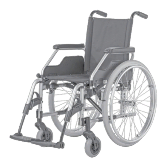
OVERVIEW The overview shows, representative for all models, the most important components of the wheelchair. Pos. Description (8) Steering wheel (1) Push handle (9) Driving wheel (2) Back support (10) Brake lever – pressure brake (3) Arm support (11) Handrims (4) Clothes guard (12) Locking knob –... -
Page 9: Brake
BRAKE By locking the brakes with the brake lever (1), the wheelchair is secured against rolling away unintentionally (parking brake). Depending on the version, the wheelchair can be equipped with pressure brakes (2) or with drum brakes (3). ☞ Note: Therefore observe the Maintenance schedule on page 29 as well as safe- ty and general handling instructions... -
Page 10: Drum Brake For Accompanying Persons
Drum brake for accompanying persons The drum brake is activated by the accom- panying person through the brake levers (1). Function as operating brakes Pull both brake levers evenly and only light- ly in order to achieve a controlled decelera- tion of the wheelchair. -
Page 11: Brake Lever Extension
Brake lever extension The brake lever extensions multiply the ap- plied brake force and reduce the force you need to apply in order to lock the brakes (1). Attention: Do not use the grips of the brake lever as support! Do not pull off the brake lever exten- sion whilst in motion. -
Page 12: Leg Supports
LEG SUPPORTS Attention: Before any actions on the leg supports the wheelchair is to be secured against unintentional rolling motions. – View chapter Brake on page 9 Folding up the footplates The footplates are to be folded up for en- try into, exiting the wheelchair or "scuttling"... -
Page 13: Turning The Leg Supports To The Side
Turning the leg supports to the side For easy transfer out of/into the wheelchair as well as driving closer to a closet, bed or bathtub the leg supports can be swivelled away toward the in-/outside [1]. – Therefore pull or press the respective locking lever (2) and swivel the corre- sponding leg support inward/outward. -
Page 14: Removing The Leg Supports
Removing the leg supports For easy transfer into and out of the wheel- chair as well as a reduced wheelchair length (important for transport) the leg supports can be removed [1]. Loosen or remove the calf belt, if availa- ble, on one side. 2. - Page 15 Height adjustment of the leg support Attention: Never put the free hand into the adjust- ment mechanism while adjusting the height adjustable leg support. – Dan- ger of crushing! Have the leg support secured by an accompanying person against uninten- tionally falling down.
-
Page 16: Arm Supports
ARM SUPPORTS The arm supports [1] can (depending on the model) be removed, are height adjustable [2] and at the same time serve as a padded arm support, clothes guard and wind break- Attention: No not grab between the frame and arm support. -
Page 17: Inserting The Arm Support
Inserting the arm support According to model and design: First insert the arm support beside the seat surface from the top into the guide [1]. Then press the arm support down and low- er the locking lever (2). ☞ Note: The rear fitting hook [3] or tube of the arm support [4] has to lie in the guide groove on the back. -
Page 18: Swivelling Up The Arm Support
Swivelling up the arm support For transfer out of/into the wheelchair the arm support can be swivelled upward as well as folded behind the back support [1]. – Fold up the locking lever (2) in order to swivel the arm support upward. –... -
Page 19: Height Adjustable Arm Supports
Height adjustable arm supports The padded arm supports are height ad- justable in 7 steps of 10.5 cm each [1]. Height adjustment Code 81: – Pull the padded arm support up to the desired height [1]. – To lower the padded arm support, pull the locking lever (2) over to the top. -
Page 20: Back Support
BACK SUPPORT On some models we offer angle adjustable back supports [1]. Back support with angle adjust- ment 30° The back support can be reclined in three positions of each 10°. Pull both levers (2) up and adjust the back support to the desired angle. 2. -
Page 21: Push Handles
PUSH HANDLES The height adjustable push handles are about 30 cm continuously height adjust- able, turnable in steps of 30° and secured against being pulled out [1]. Push handles with clamping device ☞ In doing so, hold onto the push handle that is to be adjusted with one hand. - Page 22 Height adjustable push handles with tube guide The push handles [1] are guided swiv- el-proof inside the back tube and steplessly height by up to 10 cm. Height adjustment: ☞ In doing so, hold onto the push handle that is to be adjusted with one hand. Swivel the respective clamping lever (2) with one hand into the horizontal po- sition.
-
Page 23: Wheels
WHEELS Drive wheels The drive wheels are mounted on a fixed axle [1] or on a quick release axle [2]. ☞ Note: The air pressure value for the tyres of the wheelchair can be read in the Technical data on page 31 or details on both sides of the tyre cover. -
Page 24: Specialities For Double Handrims
Specialities for double handrims The wheelchair can be propelled with on hand with the double handrim [1]. Attention: Before each ride ensure the secure fit of the connection rod (2)! Propelling the wheelchair Both handrims are to be operated simulta- neously to drive straight forward. -
Page 25: Support Castors
SUPPORT CASTORS Code 691 To increase tilting stability each side can be equipped with one bent tubing with two small wheels which can be inserted into the lower frame tubing from the rear [1]. Support castor length The support castors must protrude beyond the drive wheels, identically on both sides, by at least their diameter in order to have an adequate anti-tip function. -
Page 26: Swing-Out Support Castors
Swing-out support castors The support castors [1] can be swivelled in- ward underneath the seat [2]. ☞ Swivelling of the support castors can be done by an accompanying person or aid. ☞ Free foot space for the accompanying person with the support castors swung inwards. -
Page 27: Wheelchair Folding/Unfolding/Carrying
WHEELCHAIR FOLDING/ UNFOLDING/CARRYING Without the help of tools your wheelchairs can be folded and carried in only a few steps [1]. ☞ Note: In document Safety and general han- dling instructions < Mechanical and muscle powered wheelchairs > observe chapter < Wheelchair folding/unfolding/ carrying >... -
Page 28: Loading And Transportation
LOADING AND TRANSPORTATION Transport security The wheelchair is only to be secured through the four securing points (2) and (3). ☞ The anchor positions are marked with the symbol (4). ☞ The procedure for securing the wheel- chair can be read in the document Safety and general handling instruc- tions <... -
Page 29: Maintenance Schedule
Maintenance schedule WHEN WHAT REMARK Before starting out Test brakes for fault- Carry out test yourself or less operation with a helper. Activate brake lever to the limit. The locked wheels should not be able to turn under operating condi- tions. - Page 30 WHEN WHAT REMARK Before starting out Check the back tubes Carry out the test yourself and frame tubes for or by a helper. damages If deformations or cracks occur in the welding seams, contact a specialist workshop immediately for repairs. – Danger of acci- dents! Especially before driving in Check the lighting...
-
Page 31: Technical Data
TECHNICAL DATA Tyre pressure of pneumatic tyres Maximum tyre pressure is printed on the All data given in the < Technical data > refers tyres on each side. to the standard version. Full tyre pressure – steering wheel The overall length depends on the position and size of the drive wheels. -
Page 32: Model 1.750
Seat height, without cushion (seat surface height at front edge): Model 1.750 ..............39 / 40 / 42 / 43 / 43.5 / 45 / 47 / 48.5 / 50 / 51.5 cm Model 1.760 ....................43 / 43.5 / 45 / 47 / 48.5 / 50 / 51.5 cm Arm support height from seat surface: ......................23 cm... -
Page 33: Model 1.750 / 1.760
Seat inclination: Model 1.750 / 1.760: ..........................min. 0° / max. 4° Manufacturer setting ................................4° Leg support angle: ................................111° Foot support to seat, without seat cushion (lower shank length): with leg supports code 808: ....................min. 35 / max. 52 cm with foot board code 54: ......................min. - Page 34 Model 1.760 reinforced version: ......................max. 220 kg max. user weight (including additional load): Model 1.750: ..................................130 kg Model 1.750 transport in a HTV: .......................... 100 kg Model 1.760: ..................................160 kg Model 1.760 reinforced version: ......................max. 200 kg Max. additional loading: .............................10 kg Empty weight: Model 1.750 / 1.760: ...............................16 kg...
- Page 35 Model: .......................1.840 / 1.850 Type plate: ............................ at the crossbrace tube Life span: ..................................4 years Dimensions Overall length: with leg supports: ......................min. 1020 / max. 1090 mm without leg supports: ............................775 mm ☞ With the driving wheel position in the rear, the length is extended by 70 mm. Overall width: .........................min.
- Page 36 Seat inclination: ............................min. 0° / max. 4° Manufacturer setting ................................4° Leg support angle: ................................111° Foot support to seat, without seat cushion (lower shank length): Model 1.840: ...........................min. 35 / max. 46 cm Model 1.850: ............................min. 38 / max. 52 cm Wheels Steering wheel: ø...
-
Page 37: Transport Weight
Permitted inclination/slopes max. obstacle height (depending on the setting of the leg support height): ..0 to 100 mm Minimal turning radius: .............................1250 mm max. permissible rising gradient: ........................4.5° (8 %) max. permissible falling gradient: .........................4.5° (8 %) max. permissible transverse gradient: .......................4.5° (8 %) static tilting safety in all directions: .......................6°... -
Page 38: Meaning Of The Labels On The Wheelchair
Meaning of the labels on the wheelchair Attention! Read the operating manuals and other provided documen- tation. Do not lift the wheelchair at the arm supports or leg sup- ports. Removable parts are not suitable for carrying. Attention Readjust the brakes. Attention Increased danger of tilting when on inclinations / slopes, es- pecially in combination with short wheel base... -
Page 39: Meaning Of The Symbols On The Type Plate
Meaning of the symbols on the type plate Manufacturer Order number Serial number Production date (Year – Calendar week) Permitted user weight max. permissible total weight Permitted axle weights Max. permissible rising gradient Max. permissible falling gradient Permitted maximum speed The product is approved as a seat within a motor vehicle The product is not approved as a seat within a motor vehicle. -
Page 40: Inspection Certificate
INSPECTION CERTIFICATE Recommended safety inspection 1st year (at least every 12 months) Vehicle data: Stamp of specialist dealer: Model: Signature: Delivery note no.: Place, date: Serial-no.(SN): Next safety inspection in 12 months Date: Recommended safety inspection 2nd year Recommended safety inspection 3rd year (at least every 12 months) (at least every 12 months) Stamp of specialist dealer:... -
Page 41: Notes
NOTES... -
Page 42: Warranty / Guarantee
WARRANTY / GUARANTEE norm specifications cannot be declared as warranty or guarantee claims. We accept legal liability for this product Attention: within the scope of or general terms and Failure to observe the instructions in conditions and warranty and the guaran- the operating manual, improperly car- tee according to our described quality ser- ried out maintenance work and, espe-... -
Page 43: Warrantee / Guarantee Section
Warrantee / Guarantee section Please fill out! Copy if necessary and send the copy to the specialist dealer. Warranty / Guarantee Model designation: Delivery note no.: SN (view type plate): Date of delivery: Stamp of the specialist dealer: Inspection certificate for transfer Vehicle data: Serial-no.(SN): Stamp of specialist dealer:... - Page 44 Your specialist dealer MEYRA GmbH Meyra-Ring 2 D-32689 Kalletal-Kalldorf +49 5733 922 - 311 +49 5733 922 - 9311 info@meyra.de www.meyra.de MEYRA 205 303 001 (Status: 2013-10) All technical modifications reserved.