Wolf CT30I/S Instructions Manual
Cti series
Hide thumbs
Also See for CT30I/S:
- Use & care manual (20 pages) ,
- Specification sheet (2 pages) ,
- Specifications (2 pages)

Related Manuals for Wolf CT30I/S


Summary of Contents for Wolf CT30I/S
- Page 1 subzero.com 800.222.7820 CT Induction Cooktop Service Manual General Information Installation Information Controls & Operation Component Access & Removal Troubleshooting Guide Technical Data Wiring Diagrams...
-
Page 2: Important Safety Information
Technicians. The information and images are the copyright property of Wolf Appliance, Inc., an affiliate of Sub-Zero, Inc. Neither this manual nor any information or images contained herein may be copied or used in whole or in part without the express written permission of Wolf Appliance, Inc., an affiliate of Sub-Zero, Inc. -
Page 3: Warranty Information
Induction Cooktop (CTI) Series General Information WARRANTY INFORMATION This page contains a summary of the 2 & 5 Year Warranty that is supplied with every Wolf product, followed by details and notes about the warranties. TWO & FIVE YEAR Warranty Summary •... -
Page 4: Model Number Key
Induction Cooktop (CTI) Series Induction Cooktop (CTI) Series General Information MODEL NUMBER KEY Refer to this key for an example of the model numbers. Model: CT 15 I / S Product Type Size Fuel Feature (If Applicable) Finish Product Type CT Cooktop IM Integrated Gas Multifunction Cooktop IG Integrated Grill Cooktop... -
Page 5: Model Configurations
Model Numbers Descriptions CT15I/S Cooktop 15” Induction, Stainless Steel Trim OFF ON HIGH MELT OFF ON HIGH CLEAR 30'' Induction Cooktop Framed (CT30I/S) MELT OFF ON HIGH Model Numbers Descriptions OFF ON HIGH CT30I/S Cooktop 30” Induction, Stainless Steel Trim... -
Page 6: Model Features
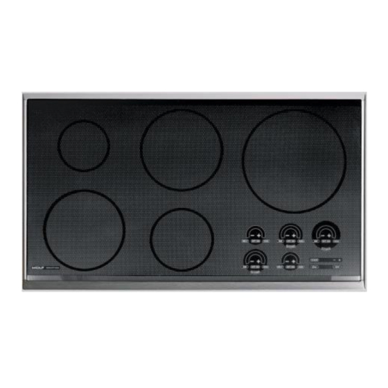
Induction Cooktop (CTI) Series Induction Cooktop (CTI) Series General Information MODEL CONFIGURATIONS 36'' Induction Cooktop Framed (CT36I/S) Model Numbers Descriptions CT36I/S Cooktop 36” Induction, Stainless Steel Trim MELT OFF ON HIGH OFF ON HIGH OFF ON HIGH CLEAR OFF ON HIGH MELT OFF ON... - Page 7 This section of the manual covers some of the installation issues a service technician may need to know when serv- icing a Wolf Induction Cooktop. If additional information is needed after reviewing this section, please refer to the Installation Guide or contact the Wolf Appliance Customer Service Department.
- Page 8 Site Preparation NOTE: Installation of the Wolf induction cooktop must meet the following location requirements. All dimensions list- ed are minimum requirements for safe operation. • FAILURE TO LOCATE THE COOKTOP WITHOUT THE PROPER CLEARANCES WILL RESULT IN A FIRE HAZ- ARD.
-
Page 9: Installation Information
Induction Cooktop (CTI) Series Induction Cooktop (CTI) Series Installation Information INSTALLATION DIMENSIONS FOR CT15I 13-3/8” (340) (Refer to Illustrations to the right & below) COOKTOP CUT-OUT WIDTH This cooktop is designed to fit a standard 24” (610 mm) width base cabinet with a 25” (635 mm) deep counter top. - Page 10 Before making the counter top cut-out, verify that the cooktop will clear the side walls of the base cabinet 19-1/4” (489) below. A Wolf 30” (762mm) or 36” (914mm) built-in COOKTOP 2-1/2” MIN single oven may be installed below Model CT30I. For...
- Page 11 INSTALLATION ONLY CUT-OUT DEPTH will clear the side walls of the base cabinet below. A 1-9/16"(40) Wolf 30” (762mm) built-in single oven may be installed below a CT30IU. For this installation, unless the cabi- FRONT OF COUNTERTOP 2-7/16"(62) nets are deeper than 24”(610mm), it is recommended...
- Page 12 Before making the counter top cut-out, verify that the cooktop will clear the side walls of the base cabinet 19-1/4” (489) below. A Wolf 30” (762mm) or 36” (914mm) built-in sin- COOKTOP 2-1/2” MIN gle oven may be installed below Model CT36I. For this...
- Page 13 INSTALLATION ONLY CUT-OUT DEPTH cooktop will clear the side walls of the base cabinet 1-9/16"(40) below. A Wolf 36” (762mm) built-in single oven may be installed below Model CT36IU. For this installation, FRONT OF COUNTERTOP 2-7/16"(62) unless the cabinets are deeper than 24” (610mm), it is...
- Page 14 Wolf dealer for information on these accessory components. Ventilation Options NOTE: It is recommended that you operate the Wolf induction cooktop with either a Wolf cooktop ventilation hood, downdraft system or Pro ventilation hood. Contact your Wolf dealer for details.
-
Page 15: Cooktop Installation
NOTE: Do not seal the cooktop to the counter top. The cooktop must be removable if service is necessary. IF THE CERAMIC GLASS TOP OF COOKTOP IS BROKEN, TURN OFF POWER TO UNIT. DO NOT OPERATE UNTIL GLASS HAS BEEN REPLACED BY A WOLF AUTHORIZED SERVICE CENTER. Cooktop... - Page 16 Electronic Control ELECTRONIC CONTROL & COMPONENT DESCRIPTIONS Wolf Induction cooktops utilize an electronic control system. The electronic control system monitors, regulates and controls a variety of functions. The control system also displays error codes to identify possible problems with the unit.
- Page 17 Induction Cooktop (CTI) Series Induction Cooktop (CTI) Series Electronic Control PRINCIPLES OF INDUCTION Introduction There are two techniques of glass-ceramic heating: • Infrared • Induction The difference is only obvious once the cooking zones are turned on. Induction has no visible indication of opera- tion.
- Page 18 OFF ON HIGH OFF ON HIGH 1800 Watt with 3000 Watt Boost 1200 Watt MELT OFF ON HIGH CLEAR MELT OFF ON HIGH CLEAR 30'' Induction Cooktop (CT30I/S Shown) Touch Control Panel Layout. #821684 - Revision B - March, 2013...
-
Page 19: Electronic Control
Induction Cooktop (CTI) Series Induction Cooktop (CTI) Series Electronic Control TOUCH CONTROL PANEL LAYOUT: CT36I/S & CT36IU 1200 Watt 1800 Watt with 3000 Watt Boost 3000 Watt with 4000 Watt Boost 1800 Watt with 3000 Watt Boost 1200 Watt MELT OFF ON HIGH OFF ON HIGH OFF ON... -
Page 20: Induction Cooktop Operation
Induction Cooktop (CTI) Series Electronic Control INDUCTION COOKTOP OPERATION Control Operation The Wolf Induction cooktop operates by adjusting the current to the induction coils. As the power level is increased on the control panel, the induction coils will output more power. - Page 21 Induction Cooktop (CTI) Series Induction Cooktop (CTI) Series Electronic Control Pressing the SIM key, activates 1 LED with a power level equivalent to 1 (See Figure 3-3). The same action takes place when the MELT key is pressed. Pressing the HIGH key activates 16 LEDs with a power level equivalent to 10 (See Figure 3-4).
- Page 22 Induction Cooktop (CTI) Series Induction Cooktop (CTI) Series Electronic Control Hot Surface LED As an added safety precaution, a HOT surface indicator light will illuminate when the surface temperature of the CLEAR glass is above 140°F(65°C). Even if the cooktop con- trols are turned off, the indicator light will illuminate to show the user that the cooktop surface remains hot Hot Surface Indicator...
- Page 23 Induction Cooktop (CTI) Series Induction Cooktop (CTI) Series Electronic Control Showroom Mode This mode deactivates the induction coils while still giv- ing the user complete functionality of the controls at either 120V or 240V power. To activate Showroom Mode, press and hold the front element MELT key for 5 seconds while in Diagnostic Mode (See page 3-11).
- Page 24 Induction Cooktop (CTI) Series Induction Cooktop (CTI) Series Electronic Control Annunciator The annunciator volume is adjustable. The volume can be adjusted through the timer controls as a User Option. The unit must be in Idle Mode (see page 3-6) in order to adjust either the volume or the frequency.
-
Page 25: Diagnostics Mode
Induction Cooktop (CTI) Series Induction Cooktop (CTI) Series Electronic Control DIAGNOSTICS MODE To enter Diagnostics Mode, the unit must be in Lock CLEAR Mode (See page 3-6). Press and hold the universal OFF key for five seconds, the controls will enter Diagnostics mode 1. -
Page 26: Component Access And Removal
COMPONENT ACCESS AND REMOVAL This section explains how to access and remove components from a Wolf Induction cooktop. Depending on which component you are going to access or remove in the following sections, you may have to remove some components first. - Page 27 Induction Cooktop (CTI) Series Induction Cooktop (CTI) Series Component Access & Rmvl TO AVOID ELECTRICAL SHOCK, POWER TO THE UNIT MUST BE DISCONNECTED BEFORE ATTEMPTING TO REMOVE THE GLASS TOP. Glass Top Assembly Removal The cooktop appliance will need to be removed from its installation in order to remove the glass top assembly.
-
Page 28: Troubleshooting Guide
Induction Cooktop (CTI) Series Induction Cooktop (CTI) Series Troubleshooting Guide DIAGNOSTICS MODE To enter Diagnostics Mode, the unit must be in Lock CLEAR Mode (see Section 3, Electronic Control, page 3-6, for a description of how to put the unit into Lock Mode). Press and hold the universal OFF key for 5 seconds, the controls will enter Diagnostics Mode 1. - Page 29 Induction Cooktop (CTI) Series Induction Cooktop (CTI) Series Troubleshooting Guide CONTROL TEMPERATURE TEST (Third Test) 1. To enter Control Temperature Test, press the “+” key of the 3000W inductor controls. The 3000W bar graph will show 4 LEDs. 2. The 3-digit display illuminates Ambient Control Temperature in °F. Press the “-”...
- Page 30 Induction Cooktop (CTI) Series Induction Cooktop (CTI) Series Troubleshooting Guide SOFTWARE VERSION (Seventh Test) 1. To enter Software Version, press the “+” key of the 3000W element controls. The 3000W bar graph will show 15 LEDs. 2. The Timer display will illuminate the software version (scrolling if necessary). 3.
- Page 31 Induction Cooktop (CTI) Series Induction Cooktop (CTI) Series Troubleshooting Guide Error Mode Error codes are organized in a priority-based scheme which allows for different behavior based on the priority of the error. There are three priority levels, defined as follows: Priority 1: Priority 1 errors are considered safety related or of such catastrophic scope that the control is considered inoperable.
-
Page 32: Error Condition
Induction Cooktop (CTI) Series Induction Cooktop (CTI) Series Troubleshooting Guide ERROR DISPLAYED ERROR POSSIBLE SOURCE(S) OF NOTES PRIORITY ERROR # CONDITION FAILURE / ACTION REQUIRED No Indicator Power loss The control panel will turn off display and shut off all burners. - Page 33 Induction Cooktop (CTI) Series Induction Cooktop (CTI) Series Troubleshooting Guide ERROR DISPLAYED ERROR POSSIBLE SOURCE(S) OF NOTES PRIORITY ERROR # CONDITION FAILURE / ACTION REQUIRED Generator 1: Burners associated with 1. Faulty cable connection Comm. Error generator 1 disabled, if Action: Check (J1, J2, or J3) connections.
- Page 34 Induction Cooktop (CTI) Series Induction Cooktop (CTI) Series Troubleshooting Guide ERROR DISPLAYED ERROR POSSIBLE SOURCE(S) OF NOTES PRIORITY ERROR # CONDITION FAILURE / ACTION REQUIRED Generator 1: Effected burner is not LED board failure. Burner (F,FR,FC) available. Action: Perform LED test #1 and if all ‘ON LED’...
- Page 35 Induction Cooktop (CTI) Series Induction Cooktop (CTI) Series Troubleshooting Guide ERROR DISPLAYED ERROR POSSIBLE SOURCE(S) OF NOTES PRIORITY ERROR # CONDITION FAILURE / ACTION REQUIRED Generator 1: The effected burner will 1. Induction generator failure. Shorted heat sink shutdown. Action: Perform Heatsink test #4 and if thermistor.
- Page 36 Induction Cooktop (CTI) Series Induction Cooktop (CTI) Series Technical Data • THIS APPLIANCE MUST BE PROPERLY GROUNDED AT ALL TIMES WHEN ELECTRICAL POWER IS APPLIED. • DO NOT GROUND APPLIANCE WITH NEUTRAL (WHITE) HOUSE SUPPLY WIRE. A SEPARATE GROUND WIRE MUST BE UTILIZED. •...
-
Page 37: Wiring Diagrams
Induction Cooktop (CTI) Series Induction Cooktop (CTI) Series Wiring Diagrams WIRING DIAGRAM - This wiring information is provided for use by qualified service personnel only. Model: CT15I/S - Disconnect appliance from electrical supply before beginning service. - Be sure all grounding devices are connected when service is complete. - Failure to observe the above warnings may result in severe electrical shock. -
Page 38: Wiring Diagram
WIRING DIAGRAM - This wiring information is provided for use by qualified service personnel only. Model: CT30I/S & CT30IU - Disconnect appliance from electrical supply before beginning service. - Be sure all grounding devices are connected when service is complete. - Page 39 Induction Cooktop (CTI) Series Induction Cooktop (CTI) Series Wiring Diagrams WIRING DIAGRAM - This wiring information is provided for use by qualified service personnel only. Model: CT36I/S & CT36IU - Disconnect appliance from electrical supply before beginning service. - Be sure all grounding devices are connected when service is complete. - Failure to observe the above warnings may result in severe electrical shock.