Table of Contents
Advertisement
Advertisement
Table of Contents

Related Manuals for LG WM2496*M Series


Summary of Contents for LG WM2496*M Series
-
Page 1: Safety Notices And Warnings
TRAINING MANUAL WM2496 Washer Training Spring 2007 Service Digital Appliance... -
Page 2: Table Of Contents
WM2496H*M Contact Information cover Safety Notices and Warnings Contents Introduction Specifications Features Display and Controls Warranty Serial Number Identification Fuzzy Logic Door Lock Door Locked Lamp Water Circulation Parts Identification (Callout) Accessories Remote Monitor and Modem Installation Pedestal Connections Water Drain Electrical Program Chart... - Page 3 Diagnosis and Troubleshooting No Power Noise and Vibration During Spin SpinSense (to resolve vibration issues) No Water Supply Detergent Does Not Flow In Bleach and Softener Do Not Flow In Heater Operation Without Water Abnormal Sound Drain Malfunction Wash Heater Malfunction (No Heating) Heater Malfunction (Continuous Overheating) No Water Circulation Spin Malfunction...
-
Page 4: Introduction
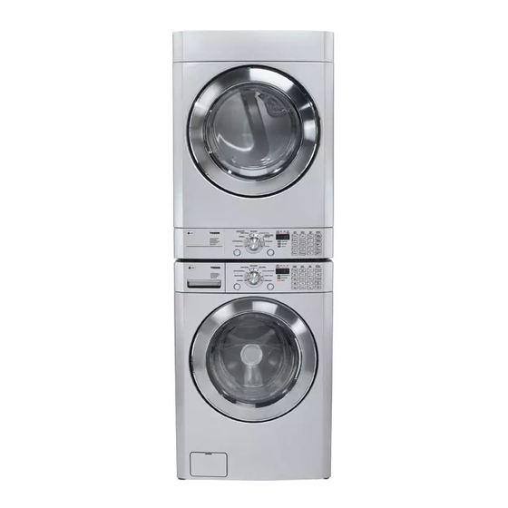
INTRODUCTION The WM2496 washer and dryer are very similar to the previous series, with the exception of the re-shaped front panel and the convertible dryer control. The WM2496 machines are specifically designed to be sold as a stacked product, and the dryer is delivered with the control panel mounted at the bottom of the dryer. -
Page 5: Specifications
SPECIFICATIONS WM2496H*M Page 5 of 58 TRAINING MANUAL... -
Page 6: Features
FEATURES LARGE CAPACITY The larger drum (4.0 cu. ft.) allows washing of larger (heavier) loads and oversized items (comforters, curtains, blankets, etc.) There is less wrinkling and tangling of the laundry. DIRECT DRIVE The brushless DC motor drives the drum directly without belts, pulleys, or transmissions. -
Page 7: Display And Controls
FEATURES, continued BUILT-IN HEATER The internal heater helps maintain the water temperature at its optimal temperature for selected cycles. The SANITARY cycle kills most common germs and bacteria. CHILD LOCK This allows the user to lock the controls. Children then cannot play with the buttons and disturb the wash cycle. -
Page 8: Warranty
WARRANTY WM2496H*M Page 8 of 58 TRAINING MANUAL... -
Page 9: Serial Number Identification
SERIAL NUMBER IDENTIFICATION The serial number is unique to each product. It gives information concerning the time and place of manufacture. The serial number is required to be paid for warranty service and to get the correct part in the event a running production change was made. -
Page 10: Fuzzy Logic
FUZZY LOGIC To get the best washing performance, the user selects one of the standard cycles and sensors in the WM2496 make an infinitely variable number of adjustments as the cycle progresses. Adjustments are automatically made for load size, incoming water temperature, soil level, rinses required, and other variables. -
Page 11: Water Circulation
WATER CIRCULATION The recirculation pump circulates the water during most of the cycle. During the WASH cycle, it runs continuously for the first 3 minutes and then intermittently throughout the cycle. During the RINSE cycle, it runs continuously as soon as the appropriate amount of rinse water has been added. -
Page 12: Parts Identification (Callout)
PARTS IDENTIFICATION The air vent on the back of the machine must be left open and clear at all times. If the washer is installed in a closet or closed laundry alcove, there must be sufficient clearance and ventilation. The closet should have a full louvered door with at least 350 square inches (0.5 m ) of open area for ventilation. -
Page 13: Accessories
ACCESSORIES The washer comes with the two input hoses. The blue stripe is for cold water and the red stripe is for hot water. While the hoses appear to be mechanically identical, the temperature and pressure ratings are different. It is critical to the performance of the washer to have the hot and cold hoses connected correctly. -
Page 14: Remote Monitor And Modem
REMOTE MONITOR and MODEM The remote laundry monitor (RLM) allows the user to monitor the progress of both washer and dryer, provided they are both equipped with a modem. Remove the cover and install the modem on the back of the washer. Save the small socket cover and screws in the event you need to remove the modem for some reason. -
Page 15: Installation
INSTALLATION REMOVE THE SHIPPING BOLTS. INSTALL THE WASHER ON A FIRM, FLAT SURFACE. ADJUST THE FEET TO BE LEVEL. If you’re installing the washer on a pedestal, install the pedestal now. (See next page.) WM2496H*M Page 15 of 58 TRAINING MANUAL... -
Page 16: Pedestal
INSTALLATION (PEDESTAL KIT) This procedure covers installing and leveling the 7½” and 13” pedestals for 27” washers, dryers, and combos. If the products are stacked, the washer must be below the dryer, and you’ll use only one pedestal. Remove the pedestal, installation hardware, and instructions form the shipping carton. - Page 17 PEDESTAL, continued Depending upon the model, your pedestal may have straight or curved brackets. The curved ones are to be used on the rear positions when mounting a dryer to a pedestal, but can also be used in any other position on the pedestal.
-
Page 18: Connections
CONNECTIONS WATER Be sure the rubber washer is inside the hose end. Attach the hoses to the washer (red is HOT, blue is COLD). Tighten them firmly but don’t strip the plastic threads on the washer connections. The hoses may appear to be mechanically identical, but the hot hose is rated at a higher temperature and burst strength. -
Page 19: Program Chart
PROGRAM CHART This chart shows the components and their times of operation in the various wash cycles. The time estimates shown here are for the basic cycles before the fuzzy logic adjustments are made. BEFORE PERFORMING SERVICE • Be careful to avoid electric shock when disconnecting parts for troubleshooting. -
Page 20: Dispenser
DISPENSER The dispenser drawer is a multi-chambered reservoir that allows the user to add all the appropriate laundry additives before starting the cycle. It has a place for pre-wash detergent, main wash detergent, fabric softener, and bleach. Powdered or liquid detergents may be used, but softener and bleach must be liquids. Detergents should carry the HE designation. - Page 21 The dispenser works by using various solenoids to apply water to different compartments. The liquid products are dispensed from a siphon box. As the appropriate chamber is flooded, the box fills and the water flushes the laundry product into the tub. It is mixed with water before contacting the laundry to prevent spotting or damaging the fabric.
-
Page 22: Test Mode
TEST MODE The WM2496 washer must be empty and off to enter the test mode. 1. Press and hold NO SPIN and LIGHT SOIL LEVEL. 2. Press POWER. 3. Press START/PAUSE to cycle through the test modes. (See chart.) CHECK SUMS WM2277H* 1F:81 WM2077CW... -
Page 23: Error Display (Error Codes)
ERROR DISPLAY • Press START/PAUSE when an error code is displayed (except PE) and the machine will PAUSE. • If the error code (PE, tE, or DE) is not cleared within 20 seconds, the machine will power OFF. • Error code FE will NOT cause the machine to power OFF. •... - Page 24 ERROR CODES, Continued WM2496H*M Page 24 of 58 TRAINING MANUAL...
-
Page 25: Diagnosis And Check Lists
DIAGNOSIS and CHECK LIST (Abnormal Operation) WM2496H*M Page 25 of 58 TRAINING MANUAL... -
Page 26: Oversudsing
WM2496H*M Page 26 of 58 TRAINING MANUAL... -
Page 27: Diagnosis And Troubleshooting
FAULT DIAGNOSIS and TROUBLESHOOTING NO POWER WM2496H*M Page 27 of 58 TRAINING MANUAL... -
Page 28: Noise And Vibration During Spin
NOISE and VIBRATION DURING SPIN If the washer is properly leveled and there is still a vibration caused by resonance at a particular speed, see SpinSense on page 29 of this manual. WM2496H*M Page 28 of 58 TRAINING MANUAL... -
Page 29: Spinsense (To Resolve Vibration Issues)
SPINSENSE SpinSense is a software adjustment that allows a small adjustment in the spin speeds to eliminate excessive vibration, particularly vibration caused when the selected spin speed strikes a harmonic value in the floor and causes resonance. To adjust the spin speeds to eliminate this issue, apply SpinSense using the following steps. -
Page 30: No Water Supply
NO WATER SUPPLY DETERGENT DOES NOT FLOW IN (See DISPENSER, page 20.) WM2496H*M Page 30 of 58 TRAINING MANUAL... -
Page 31: Bleach And Softener Do Not Flow In
LIQUID SOFTENER and BLEACH DO NOT FLOW IN (See DISPENSER, page 20.) ABNORMAL SOUND WM2496H*M Page 31 of 58 TRAINING MANUAL... -
Page 32: Heater Operation Without Water
HEATER OPERATION WITHOUT WATER DRAIN MALFUNCTION WM2496H*M Page 32 of 58 TRAINING MANUAL... -
Page 33: Wash Heater Malfunction (No Heating)
WASH HEATER MALFUNCTION HEATER MALFUNCTION (CONTINUOUS OVERHEATING) WM2496H*M Page 33 of 58 TRAINING MANUAL... -
Page 34: No Water Circulation
NO WATER CIRCULATION WM2496H*M Page 34 of 58 TRAINING MANUAL... -
Page 35: Spin Malfunction
SPIN MALFUNCTION ERROR CODE WM2496H*M Page 35 of 58 TRAINING MANUAL... -
Page 36: Disassembly And Repair
DISASSEMBLY and REPAIR The following pages will show the instructions for disassembly, repair, replacement of parts, and re-assembly. Many times, electrical components may be tested by connecting the appropriate meter to the leads or connectors on the main PC Board. (Refer to the block wiring diagram, below.) Proper diagnosis will eliminate unnecessary labor and expedite repairs. -
Page 37: Top Plate
DISASSEMBLY/REPAIR (Control Panel) Remove two screws on the back of the top plate. Pull the top plate backward and lift, as shown. Remove the detergent drawer. Remove two screws behind the detergent drawer. Disconnect the connector for the Display PWB. (control panel not exactly as pictured) Remove one screw from the corner of the control panel. -
Page 38: Main Board
DISASSEMBLY/REPAIR (Main Board) Often, you can diagnose a failed part by removing its connector on the main board and connecting the tester to the leads in the connector. (See page 51.) Disconnect the POWER connector and the Water Level Sensor Switch. Remove the protective cover. -
Page 39: Dispenser
DISASSEMBLY/REPAIR (Dispenser) Remove the top plate. (See page 37.) Remove the dispenser drawer. Remove two screws to release the dispenser. (control panel not exactly as pictured) Loosen the clamp on the large hose that runs from the dispenser to the drum. Have an old towel handy to stuff under the dispenser to soak up any spillage. -
Page 40: Front Cabinet Cover
DISASSEMBLY/REPAIR (Front Cabinet Cover) Remove the top plate. (See page 37.) Remove the control panel. (See page 37.) Remove four screws that secure the front panel. Remove the screw that secures the filter cover. Use a flat screwdriver or a putty knife to loosen the filter cover and pull it out. - Page 41 DISASSEMBLY/REPAIR (Front Cabinet Cover, continued) Open the door. Remove the clamp using special tool 383EER4001A. (See page 58.) Lean the cabinet front forward, being careful to avoid breaking the glass. The door is HEAVY. Disconnect the door switch connector. (Remember to reconnect it upon reassembly.) Lift the door and front cover off the cabinet base as an...
-
Page 42: Door
DISASSEMBLY/REPAIR (Door) Remove the door with the front cover still on the machine. Open the door. Remove seven screws from the hinge cover. Pry off the hinge cover with a flat screwdriver. Remove the screw at the bottom of the hinge. Lift the door off the hinge. -
Page 43: Pumps (Drain And Circulation)
DISASSEMBLY/REPAIR (Pumps) Remove the front cabinet. (See page 40.) Drain the water from the sump. (See page 40.) Remove the clamps and hoses. Remove two screws and push the pump backward and up. Press down the plastic tab on the base to slide the pump assembly backward. -
Page 44: Heater
DISASSEMBLY/REPAIR (Heater) Remove the front cabinet. (See page 40.) Drain the water from the sump. (See page 40.) Remove the push-on connectors from the heater. There may be a hidden release on the terminals. Remove the nut that holds the ground wire. -
Page 45: Removal Of Objects Between Tub And Drum
DISASSEMBLY/REPAIR (Object between tub and drum) Remove the top cover. (See page 37.) Remove the front cabinet cover. (See page 40.) Remove the heater. (See page 44.) Fish out the foreign object(s) using a wire or bar. WATER LEVEL SWITCH The water level detector switch monitors the water level and feeds this information to the MICOM. -
Page 46: Motor
DISASSEMBLY/REPAIR (Motor) For technical information concerning the direct drive DC motor, refer to page 47.) Remove the back cover. Remove the large bolt in the center shaft. (Your helper can hold the inside of the drum.) DO NOT stick a screwdriver through the slots in the rotor. -
Page 47: Direct Drive Motor
DIRECT DRIVE MOTOR The motor is a direct-drive, brushless, DC motor. It is attached to the drum via a splined shaft, eliminating belts, pulleys, transmissions, and the inherent problems associated with them. The rotor is attached to the shaft by one large bolt. -
Page 48: Tub And Drum
DISASSEMBLY/REPAIR (Tub and Drum) Removing the tub/drum assembly is major surgery. It is much lighter if you remove the weights and the motor. Generally speaking, you’ll have to remove all that anyway. Remove the motor. (See page 46.) Drain the water from the sump. (See page 40.) Remove the control panel. -
Page 49: Damper
DISASSEMBLY/REPAIR (Damper) Disconnect the dampers from the tub and the base. (See photos, left.) Be sure to press in the safety tab before pushing the pin out of the damper. You can use a ” socket to hold the pin in while you squeeze the pin with the special tool 383EER4003A. -
Page 50: Tips And Tricks
TIPS and TRICKS HOSES When replacing the large hoses, be sure to avoid getting the lip turned under the hose clamp. This will damage the hose and cause a leak. The large hoses have notches on the ends to index them on the connectors. Be sure the notch is pushed down all the way on the index boss. -
Page 51: Wiring Diagram
WIRING DIAGRAM WM2496H*M Page 51 of 58 TRAINING MANUAL... -
Page 52: Exploded Views
EXPLODED VIEW – Cabinet and Control Panel WM2496H*M Page 52 of 58 TRAINING MANUAL... - Page 53 EXPLODED VIEW – Drum and Tub Assembly WM2496H*M Page 53 of 58 TRAINING MANUAL...
- Page 54 EXPLODED VIEW – Dispenser Assembly WM2496H*M Page 54 of 58 TRAINING MANUAL...
-
Page 55: Parts List
PARTS LIST Loc # Part No Description AFN30385101 Owner’s Manual 3890EZ3612A Outer Box (Carton) 3W20018B Wrench (See page 58) MFL30599101 Service Manual A100 3091ER0004P Cabinet Assembly A101 3550ER1028A Rear Cover A102 4830ER3001A Bushing A103 4930ER3014A Holder A104 4011FR3159E Shipping Bolt, Upper (Short) (2) A105 4011FR3159D Shipping Bolt, Lower (Long) (2) - Page 56 Loc # Part No Description A440 6601ER1004C Door Switch/Lock A450 6871ER1104A Main PCB A455 3550ER1032A Main PCB Cover A485 6201EC1006B Line Noise Filter F110 6871ER2089A Display PCB F120 6877ER1044D Display Wiring Harness F130 6850ER2002C Flat Cable F140 6877ER1016F Wiring Harness F145 6877ER3003B Wiring Harness...
- Page 57 K105 3045ER0048B Outer Tub Assembly (Rear Half) K110 3045ER1017A Drum Assembly K111 4433ER1005A Baffle/Roller Assembly K115 4434ER0001A Spider (Drive Assembly) K121 4280FR4048N Ball Bearing K122 4280FR4048J Ball Bearing K123 4040FR4051C Main Bolt K125 4036ER2004A Main Bearing Seal K130 4866ER0007A Balance Weight, Upper K131 1SZZER4002A Screw, Custom for Weights (8)
- Page 58 383EER4001A Gasket Plier (Outer) (SPECIAL TOOL) 383EER4003A Damper Plier (SPECIAL TOOL) 383EER4004A Gasket Plier (Inner) (SPECIAL TOOL) 5214FR3018D DRAIN HOSE EXTENSION (5 FEET) 3W20018B Wrench 4769ER4001A Mushroom valve, vent 4769ER4002A Mushroom valve, fill WM2496H*M Page 58 of 58 TRAINING MANUAL...
- Page 60 © Copyright 2007 LG Electronics, Inc. Printed in the USA...