Table of Contents
Advertisement
Quick Links
Advertisement
Table of Contents

Related Manuals for Supermicro 5130AD-T


Summary of Contents for Supermicro 5130AD-T
- Page 1 High Performance Desktop System 5130AD-T USER'S MANUAL Revision 1.0...
- Page 2 State of California, USA. The State of California, County of Santa Clara shall be the exclusive venue for the resolution of any such disputes. Supermicro's total liability for all claims will not exceed the price paid for the hardware product.
-
Page 3: About This Manual
SuperServer 5130AD-T. Installation and maintenance should be performed by experienced technicians only. Please refer to the 5130AD-T server specifi cations page on our website for updates on supported memory, processors and operating systems (http://www.supermicro.com). -
Page 4: Table Of Contents
Preface Contents Chapter 1 Introduction 1.1 Overview ..........................8 1.2 Unpacking the System ......................8 1.3 System Features ........................9 1.4 Server Chassis Features ....................10 Control Panel ........................10 Front and Rear Features....................11 1.5 Motherboard Layout ......................12 Quick Reference Table ......................13 Chapter 2 Desktop Setup 2.1 Overview ..........................15 2.2 Unpacking the System .......................15 2.3 Warnings and Precautions! ....................15... - Page 5 System 5130AD-T User's Manual 3.4 Chassis Components ......................29 Key Features ........................29 Hard Drives ........................30 System Cooling .........................34 Water Cooled Heat Sink ....................36 Air Flow ..........................37 Dust Filters ........................37 Power Supply ........................38 Chapter 4 Motherboard Connections 4.1 Power Connections ......................39 4.2 Headers and Connectors ....................40 Front Control Panel .......................43...
- Page 6 Preface 6.8 Save & Exit ........................111 6.9 BIOS Update ........................113 Appendix A BIOS Error Codes A-1 BIOS Error Beep (POST) Codes ..................115 A-2 Additional BIOS POST Codes ..................116 Appendix B Standardized Warning Statements for AC Systems B.1 About Standardized Warning Statements ................117 Appendix C System Specifi...
-
Page 7: Contacting Supermicro
System 5130AD-T User's Manual Contacting Supermicro Headquarters Address: Super Micro Computer, Inc. 980 Rock Ave. San Jose, CA 95131 U.S.A. Tel: +1 (408) 503-8000 Fax: +1 (408) 503-8008 Email: marketing@supermicro.com (General Information) support@supermicro.com (Technical Support) Website: www.supermicro.com Europe Address: Super Micro Computer B.V. -
Page 8: Chapter 1 Introduction
SNK-P0051AP4 1.2 Unpacking the System Inspect the box the SuperServer 5130AD-T was shipped in and note if it was damaged in any way. If any equipment appears damaged, please fi le a damage claim with the carrier who delivered it. -
Page 9: System Features
Chapter 1: Introduction 1.3 System Features The following table provides you with an overview of the main features of the 5130AD-T. Please refer to Appendix C for additional specifi cations. System Features Motherboard C7Z270-PG Chassis GS5A-753K Supports Intel® 7th/6th Gen Core i7/i5/i3 series processor... -
Page 10: Server Chassis Features
1.4 Server Chassis Features Control Panel The 5130AD-T features a front panel allowing easy access to the system power and communication ports. The in addition to the HDD Activity LED, the Power button and the Reset button, the following ports are available on the front panel: •... -
Page 11: Front And Rear Features
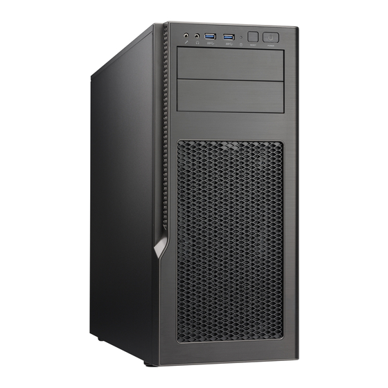
Chapter 1: Introduction Front and Rear Features The GS5A-753K is a mid-tower chassis See the illustrations below for the features included on the front and rear of the chassis. Figure 1-2. Chassis Front View Front and Rear Chassis Features Item Feature Description Front Control Panel... -
Page 12: Motherboard Layout
System 5130AD-T User's Manual 1.5 Motherboard Layout Below is a layout of the C7Z270-PG with jumper, connector and LED locations shown. See the table on the following page for descriptions. For detailed descriptions, pinout information and jumper settings, refer to Chapter 4. -
Page 13: Quick Reference Table
Chapter 1: Introduction Quick Reference Table Jumper Description Default Setting CLEAR CMOS Clear CMOS Switch Push Button Switch JBR1 BIOS Recovery Switch Pins 1-2 (Disable) JBT1 Clear CMOS (on board) Short pads to clear CMOS C1/JI SMB to PCI Slots Open (Disable) JPAC1 Audio Enable... - Page 14 System 5130AD-T User's Manual Internal Speakers U.2 CONNECTOR 1, 2 U.2 Connector 1 and 2, for 2.5” SSD Drives USB 0/1 Back Panel USB 2.0 Ports USB 2/3, USB 4/5, USB 6/7 Front Panel Accessible USB 2.0 Headers USB 8/9 Back Panel USB 3.0 Ports...
-
Page 15: Chapter 2 Desktop Setup
Desktop Setup 2.1 Overview This chapter provides a quick setup checklist to get your 5130AD-T up and running. Following these steps in the order given should enable you to have the system operational within a minimum amount of time. This quick setup assumes that your system has come to you with the motherboard preinstalled. -
Page 16: Accessing The Inside Of The System
System 5130AD-T User's Manual 2.4 Accessing the Inside of the System You may need to access the system periodically to perform maintenance or install components such as hard drives. The system features two removable side covers, allowing easy access to the system interior. -
Page 17: Front Bezel
Chapter 2: Server Installation Front Bezel Remove the front bezel by pulling it off from the bottom of the bezel. This should only be necessary when replacing the front fans. Figure 2-2. Removing the Front Bezel... -
Page 18: Chapter 3 Maintenance And Component Installation
When receiving a motherboard without a processor pre-installed, make sure that the plastic CPU socket cap is in place and none of the socket pins are bent; otherwise, contact your retailer immediately. • Refer to the Supermicro website for updates on CPU support. -
Page 19: Installing The Lga1151 Processor
Chapter 3: Maintenance and Component Installation Installing the LGA1151 Processor Begin by removing power from the system as described in Section 3.1. Installing a Processor 1. Press the load lever to release the load plate, which covers the CPU socket, from its locking position. - Page 20 System 5130AD-T User's Manual 4. Align the CPU key that is the semi-circle cutouts against the socket keys. Once it is aligned, carefully lower the CPU straight down into the socket. Warning: Do not drop the CPU on the socket. Do not move the CPU horizontally or vertically.
-
Page 21: Installing A Heatsink
Chapter 3: Maintenance and Component Installation Installing a Heatsink The use of active type heatsinks are recommended (except in 1U systems). To install a third- party heatsink, please follow the installation instructions included with the heatsink package. Installing an Active CPU Heatsink with Fan 1. - Page 22 CPU Fan connector. Note: It is recommended that you use the Supermicro SNK-P0046A4 active heatsink for this system. 10. Align the four heatsink fasteners with the mounting holes on the motherboard. Gently push the pairs of diagonal fasteners (#1 &...
-
Page 23: Removing The Heatsink
Chapter 3: Maintenance and Component Installation 12. Once all four fasteners are securely inserted into the mounting holes, and the heatsink is properly installed on the motherboard, connect the heatsink fan wires to the CPU Fan connector. Removing the Heatsink We do not recommend that the CPU or the heatsink be removed. -
Page 24: Memory Installation
(128-bit) memory, which is faster than non-interleaved (64-bit) memory. Check the Supermicro website for possible updates to memory support. Installing Memory 1. Insert the desired number of DIMMs into the memory slots, starting with DIMMA1 (see the next page for the location). -
Page 25: Removing Memory Modules
DIMMs or slots. Warning: In dual-CPU confi gurations, memory must be installed in the DIMM slots associated with the installed CPUs. Note: Visit the product page on the Supermicro website for possible updates to memory support (www.supermicro.com). -
Page 26: Memory Support
System 5130AD-T User's Manual Memory Support Towards the CPU DIMMA1 (Black Slot) DIMMA2 (Gray Slot) DIMMB1 (Black Slot) DIMMB2 (Gray Slot) Towards the edge of the motherboard The C7Z270-PG supports up to 64 GB of Unbuffered (UDIMM) non-ECC DDR4 memory, up to 3600MHz (OC) in four 288-pin memory slots. -
Page 27: Pci Expansion Card Installation
Chapter 3: Maintenance and Component Installation PCI Expansion Card Installation Installing Expansion Cards Installing an Expansion Card 1. Power down the system as described in section 6-2 and open the left side chassis cover. 2. Remove the blank PCI shield from the rear of the chassis by removing the thumb screw. 3. -
Page 28: Motherboard Battery
System 5130AD-T User's Manual Motherboard Battery The motherboard uses non-volatile memory to retain system information when system power is removed. This memory is powered by a lithium battery residing on the motherboard. Replacing the Battery Begin by removing power from the system as described in section 3.1. -
Page 29: Chassis Components
Chapter 3: Maintenance and Component Installation 3.4 Chassis Components Supermicro S5 SI Edition Titanium Black chassis (GS5A-753K) blends elegance and fl exibility into a refi ned home for your high-performance hardware. Key Features • Black anodized brushed aluminum fascia front panel with two USB 3.0 ports •... -
Page 30: Hard Drives
System 5130AD-T User's Manual Hard Drives The standard confi guration includes two 5.25" drive bays, four 2.5" drive bays, and six combination bays that can house either 3.5" or 2.5" drives. • Each 5.25" bay can be confi gured to accept a removable media drive, such as DVD, or a storage device, such as a 3.5"... - Page 31 Chapter 3: Maintenance and Component Installation Removing a Hot-Swap Drive Carrier 1. Push the release button on the carrier. 2. Swing the handle fully out. 3. Grasp the handle and use it to pull the drive carrier out of its bay. Release Tab Release Tab Figure 3-3.
- Page 32 System 5130AD-T User's Manual 2. Locate and press the release tab (Figure 6-5) for the drive tray in which you want to place the drive. 3. Push the drive tray toward the front of the chassis and out. 4. Secure the storage drive to the drive tray with screws through the bottom of the tray. To install two 2.5"...
- Page 33 Chapter 3: Maintenance and Component Installation Figure 3-6. Mounting Tray for 3.5" Drive Figure 3-7. Mounting Tray for 2.5" Drive...
-
Page 34: System Cooling
System 5130AD-T User's Manual System Cooling The chassis includes two 120mm PWM fans in the front and one 120mm PWM in the rear. Other fan mounts and confi gurations are possible. • Two front fans can be upgraded to 140mm. - Page 35 Chapter 3: Maintenance and Component Installation Adding or Changing Fans • To upgrade the standard front fans, remove the chassis front cover. • To add a fan to the chassis bottom, the lower 3.5" HDD cage must be removed. See Figure 3-9.
-
Page 36: Water Cooled Heat Sink
System 5130AD-T User's Manual Water Cooled Heat Sink The chassis supports a water cooled CPU heat sink. A 120 mm radiator can be placed over the rear fan. A 240 mm radiator can be place just under the top of the chassis. Consult your water cooling kit instructions for installation. -
Page 37: Air Flow
Chapter 3: Maintenance and Component Installation Air Flow Make sure cables do not obstruct the cooling airfl ow. Dust Filters The chassis features a dust fi lter in front of the front fans, and two magnetic dust fi lters, one on top of the chassis and one on the bottom. -
Page 38: Power Supply
System 5130AD-T User's Manual Power Supply The 5130AD-T system comes with a 750 Watt power supply. Mount it on the rear fl oor of the chassis. The power supply fan may be on top (recommended) or under the power supply. -
Page 39: Chapter 4 Motherboard Connections
Chapter 4: Motherboard Connections Chapter 4 Motherboard Connections This section describes the connections on the motherboard and provides pinout defi nitions. Note that depending on how the system is confi gured, not all connections are required. The LEDs on the motherboard are also described here. A severboard layout indicating component locations may be found in Chapter 1. -
Page 40: Headers And Connectors
System 5130AD-T User's Manual Processor Power Connector JPW2 must also be connected to the power supply. This connector is used to power the processor(s). +12V 8-pin Power Pin Defi nitions Pin# Defi nition 1 - 4 Ground 5 - 8... - Page 41 Chapter 4: Motherboard Connections Speaker (JD1) On the JD1 header, pins 3-4 are used for internal speaker. Close pins 3-4 with a cap to use the onboard speaker. If you wish to use an external speaker, close pins 1-4 with a cable. See the table on the right for pin defi...
- Page 42 System 5130AD-T User's Manual Standby Power Header (JSTBY1) The Standby Power header is located at JSTBY1 on the motherboard. See the table on the right for pin defi nitions. Standby Power Pin Defi nitions Pin# Defi nition +5V Standby Ground...
-
Page 43: Front Control Panel
Chapter 4: Motherboard Connections Thunderbolt Connector This motherboard supports one Thunderbolt interface on the back panel. Thunderbolt is a hardware interface that allows peripherals to be connected to the motherboard at transfer speeds of up to 10Gbits/s. This port combines a PCIe and a DisplayPort into one serial signal. Front Control Panel JF1 contains header pins for various control panel connections. - Page 44 System 5130AD-T User's Manual Power Fail LED The Power Fail LED connection is located on pins 5 and 6 of JF1. Power Fail LED Pin Defi nitions (JF1) Pin# Defi nition 3.3V PWR Supply Fail Overheat (OH)/Fan Fail Connect an LED cable to pins 7 and 8 of JF1 to use the Overheat/Fan Fail LED connections.
-
Page 45: Data Cables
Chapter 4: Motherboard Connections Power LED The Power LED connection is located on pins 15 and 16 of JF1. Power LED Pin Defi nitions (JF1) Pin# Defi nition 3.3V Power LED NMI Button The non-maskable interrupt button header is located on pins 19 and 20 of JF1. NMI Button Pin Defi... - Page 46 System 5130AD-T User's Manual Figure 4-2. Rear I/O Ports Rear I/O Ports Description Description Description PS/2 Keyboard/Mouse Port USB 3.0 Port 8 Surround Out USB 2.0 Port 0 LAN2 S/PDIF Out USB 2.0 Port 1 USB 3.1 Port 10 Line In Display Port USB 3.1 Port 11...
- Page 47 Chapter 4: Motherboard Connections ATX PS/2 Keyboard/Mouse Ports The ATX PS/2 keyboard and PS/2 mouse are located above Back Panel USB Ports 0/1 on the motherboard. VESA® DisplayPort™ DisplayPort, developed by the VESA consortium, delivers digital display at a fast refresh rate. It can connect to virtually any display device using a DisplayPort adapter for devices such as VGA, DVI or HDMI.
-
Page 48: Jumpers
System 5130AD-T User's Manual 4.4 Jumpers Explanation of Jumpers To modify the operation of the motherboard, jumpers are used to choose between optional settings. Jumpers create shorts between two pins to change the function associated with it. Pin 1 is identifi ed with a square solder pad on the printed circuit board. See the motherboard layout page for jumper locations. - Page 49 Chapter 4: Motherboard Connections LAN Enable/Disable Jumper JPL2 will enable or disable LAN ports 3 and 4. See the table on the right for jumper settings. The default setting is enabled. LAN1/2 Enable/Disable Jumper Settings Jumper Setting Defi nition Pins 1-2 Enabled Pins 2-3 Disabled...
- Page 50 System 5130AD-T User's Manual Watch Dog Timer Enable/Disable Watch Dog (JWD1) is a system monitor that can reboot the system when a software application hangs. Close pins 1-2 to reset the system if an application hangs. Close pins 2-3 to generate a non-maskable interrupt signal for the application that hangs. See the table on the right for jumper settings.
-
Page 51: Led Indicators
Chapter 4: Motherboard Connections 4.5 LED Indicators LAN LEDs Two LAN ports are located on the I/O back panel of the motherboard. This Ethernet LAN port has two LEDs (Light Emitting Diode). The yellow LED indicates activity, while the Link LED may be green, amber, or off to indicate the speed of the connections. -
Page 52: Chapter 5 Software
You must fi rst confi gure RAID settings (if using RAID) before you install the Windows OS and the software drivers. To confi gure RAID settings, please refer to the RAID Confi guration User Guides posted on our website at www.supermicro.com/support/manuals. Installing the Windows OS for a RAID System 1. -
Page 53: Driver Installation
Chapter 5: Software 5.2 Driver Installation The Supermicro FTP site contains drivers and utilities for your system at ftp://ftp.supermicro. com. Some of these must be installed, such as the chipset driver. After accessing the FTP site, go into the CDR_Images directory and locate the ISO fi le for your motherboard. -
Page 54: Superdoctor 5
® 5.3 SuperDoctor The Supermicro SuperDoctor 5 is a program that functions in a command-line or web-based interface for Windows and Linux operating systems. The program monitors such system health information as CPU temperature, system voltages, system power consumption, fan speed, and provides alerts via email or Simple Network Management Protocol (SNMP). -
Page 55: Chapter 6 Bios
Chapter 6: BIOS Chapter 6 BIOS 6.1 Introduction This chapter describes the AMI BIOS Setup Utility for the C7Z270-PG. The ROM BIOS is stored in a Flash EEPROM and can be easily updated. This chapter describes the basic navigation of the AMI BIOS Setup Utility setup screens. Note: For AMI BIOS Recovery, please refer to the UEFI BIOS Recovery Instructions in Appendix C. -
Page 56: Main Menu
System 5130AD-T User's Manual 6.2 Main Menu When you fi rst enter AMI BIOS Setup Utility, you will see the Main Menu screen. You can always return to the Main Menu by selecting the Main tab on the top of the screen with the arrow keys. -
Page 57: How To Change The Confi Guration Data
Chapter 6: BIOS You may press the <F1> on any screen under the Setup Section to see a list of Hot Keys that are available. Press <F12> to print the screen. The keyboard's Escape key <ESC> cancels the current screen and will you back to the previous screen. -
Page 58: System Information
System 5130AD-T User's Manual 6.3 System Information The System Information Panel displays the motherboard's confi guration. The following information among others are displayed in this section: • Motherboard Model Name - C7Z270-PG. • BIOS Version - this item displays the BIOS version number. -
Page 59: Cpu
Chapter 6: BIOS 6.4 CPU The following information are be displayed in this section: • Name - indicates the model name of the CPU. • Type - indicates the brand, model name, model number of the CPU and it's rated clock speed. -
Page 60: Cpu Confi Guration
System 5130AD-T User's Manual CPU Confi guration Set all options for the processor in this section. The following CPU information will be displayed: • CPU Type - displays the CPU type. • Type - indicates the brand, model name, model number of the CPU and it's rated clock speed. - Page 61 Chapter 6: BIOS SW Guard Extension (SGX) Select Enabled to activate the Software Guard Extensions (SGX). The options are Enabled, Disabled and Software Controlled. Select Owner EPOCH Input Type There are three Owner EPOCH modes (Each EPOCH is 64 bit). The options are No Change in Owner EPOCHs, Change to New Random Owner EPOCH and Manual User Defi...
- Page 62 System 5130AD-T User's Manual BIST Select Enabled to activate the Built-In Self Test (BIST) on reset. The options are Enabled and Disabled. Select Enable for Intel CPU Advanced Encryption Standard (AES) Instructions support to enhance data integrity. The options are Enabled and Disabled.
- Page 63 Chapter 6: BIOS Power and Performance CPU - Power Management Control Boot performance mode This option enables the selection of the default CPU performance during system boot. The options are Max Non-Turbo Performance, Max Battery and Turbo Performance. Intel(R) SpeedStep(tm) Intel SpeedStep Technology allows the system to automatically adjust processor voltage and core frequency in an effort to reduce power consumption and heat dissipation.
- Page 64 System 5130AD-T User's Manual Enhanced C-states (Available when "CPU C States" is set to Enabled) Select Enabled to enable Enhanced C1 Power State to boost system performance. The options are Enabled and Disabled. C-State Auto Demotion When this item is enabled, the CPU will conditionally demote C State based on un-cored auto-demote information.
- Page 65 Chapter 6: BIOS GT-Power Management RC6 (Render Standby) Use this feature enable Render Standby support. The options are Enabled and Disabled. Maximum GT Frequency This option is the Maximum GT Frequency as defi ned by the user. Choose between 300MHz (RPN) and 1200MHz (RP0). Any value beyond this range will be clipped to its min/max supported by the CPU.
-
Page 66: Cpu Overclocking
System 5130AD-T User's Manual CPU OverClocking BCLK Clock Frequency (1/100 MHz) Use this item to set the CPU clock override value for the host system. The default setting is 10000. FCLK Frequency for Early Power On Select the FCLK frequency for early power on. The options are Normal (800MHz), 1GHz and 400MHz. - Page 67 Chapter 6: BIOS 2-Core Ratio Limit Override This increases (multiplies) 2 clock speeds in the CPU core in relation to the bus speed when two CPU cores are active. Enter 0 to use the manufacturer's default setting. This item enables or disables the RSR feature. The options are Disabled and Enabled. Boot Performance Mode This option enables the selection of the default CPU performance during system boot.
- Page 68 System 5130AD-T User's Manual Power Limit 1 This feature confi gures Package Power Limit 1, in milliwatts. When the limit is exceeded, the CPU ratio is lowered after a period of time (see item below). A lower limit can save power and protect the CPU, while a higher limit improves performance.
- Page 69 Chapter 6: BIOS CPU Flex Ratio Override Select Enabled to activate CPU Flex Ratio programming. The options are Enabled and Disabled. CPU Flex Ratio Settings When CPU Flex Ratio Override is enabled, this sets the value for the CPU Flex Ratio. The default is 16.
- Page 70 System 5130AD-T User's Manual Offset Prefi x Use this feature to set the offset value as positive or negative. The options are + or -. PCH Voltage Use this feature to trim the PCH Voltage. Select from these values: 1.00V, 1.05V, 1.10V, 1.15V, 1.20V, 1.25V and 1.30V.
- Page 71 Chapter 6: BIOS Slow Slew Rate for IA Domain This feature sets the VR IA Slew Rate for Deep Package C-State ramp time. Slow slew rate equals Fast divided by the number 2, 4, 8, or 16. This feature is used to help reduce acoustic noise.
- Page 72 System 5130AD-T User's Manual PS Current Threshold1 The PS Current Threshold1 is defi ned in 1/4A (Amperes) increments and uses the BIOS mailbox command 0x3. A value of 400 equals 100A. Range is 0-512 which translates to 0-128A. Enter 0 for AUTO. Default is 80 for 20A.
- Page 73 Chapter 6: BIOS VR Voltage Limit This feature sets the Voltage Regulator voltage limit. The value is represented in mV. A value of 1250 equals 1.25V. Set this number to 0 for Auto. This uses the BIOS VR mailbox command 0x6. TDC Enable Enable or Disables TDC (Thermal Design Current).
-
Page 74: Memory
System 5130AD-T User's Manual 6.5 Memory The following information are be displayed in this section: • Memory RC Version • Memory Frequency • Memory Timings (tCL-tRCD-tRP-tRAS) • DIMM#A1 ~ DIMM#B2 Maximum Memory Frequency This option selects the type/speed of the memory installed. The options are 1333, 1600, 1867, 2133, 2400, 2667, 2933, and 3200. - Page 75 Chapter 6: BIOS Channel A DIMM Control This feature enables or disables the selected Channel A DIMM slot(s). The settings are Enable Both DIMMs, Disable DIMM0, Disable DIMM1 and Disable Both DIMMs. Channel B DIMM Control This feature enables or disables the selected Channel B DIMM slot(s). The settings are Enable Both DIMMs, Disable DIMM0, Disable DIMM1 and Disable Both DIMMs.
- Page 76 System 5130AD-T User's Manual Memory Profi le Use this feature to set Performance Memory Profi les which may cause impact on memory behavior. The options are Default Profi le, Custom Profi le, XMP Profi le 1 and XMP Profi le 2.
- Page 77 Chapter 6: BIOS tFAW This option selects the Minimum Four Activate Window Delay Time. Enter a numeric value between 1-586. The default is 23. Maximum tREFI Time (tREFI) This option confi gures the Maximum tREFI Time (Average Periodic Refrech Interval). Enter a numeric value.
- Page 78 System 5130AD-T User's Manual tRRD_dg This option confi gures the tRRD_dg. Enter a numeric value. The default is 4. derating ext This option confi gures the derating_ext. Enter a numeric value. The default is 2. ODT_read_duration This option confi gures the ODT Read Duration. Enter a numeric value. The default is 0.
- Page 79 Chapter 6: BIOS tRDWR_dg This option confi gures the between module read to write delay (tRDWR_dg). Enter a numeric value. The default is 4. tRDWR_dr This option confi gures the between module read to write delay (tRDWR_dr). Enter a numeric value.
- Page 80 System 5130AD-T User's Manual This option confi gures tXP. Enter a numeric value. The default is 7. tXPDLL This option confi gures tXPDLL. Enter a numeric value. The default is 26. tPRPDEN This option confi gures tPRPDEN. Enter a numeric value. The default is 2.
-
Page 81: Advanced
Chapter 6: BIOS 6.6 Advanced Boot Feature Quiet Boot Use this feature to select the screen display between the POST messages and the OEM logo upon bootup. Uncheck the box to display the POST messages. Check the box to display the OEM logo instead of the normal POST messages. - Page 82 System 5130AD-T User's Manual Watch Dog Function If enabled, the Watch Dog Timer will allow the system to reset or generate NMI based on jumper settings when it is expired for more than 5 minutes. The options are Disabled and Enabled.
- Page 83 Chapter 6: BIOS NCT6792D Super IO Confi guration SuperIO Chip NCT6792D Serial Port 1 Confi guration Serial Port This item will Enable or Disable Serial Port 1 (COM1). Place a tick mark on the box to enable Serial Port 1. The default is Enabled. Device Settings This item displays the current IRQ setting for Serial Port 1 (COM1).
- Page 84 System 5130AD-T User's Manual Serial Port Console Redirection COM 1 Console Redirection Select Enabled to enable COM Port 1 Console Redirection, which will allow a client machine to be connected to a host machine at a remote site for networking. The options are Disabled (unchecked) and Enabled (checked).
- Page 85 Chapter 6: BIOS Bits Per second Use this item to set the transmission speed for a serial port used in Console Redirection. Make sure that the same speed is used in the host computer and the client computer. A lower transmission speed may be required for long and busy lines. The options are 9600, 19200, 38400, 57600 and 115200 (bits per second).
- Page 86 System 5130AD-T User's Manual Putty KeyPad This feature selects Function Keys and KeyPad settings for Putty, which is a terminal emulator designed for the Windows OS. The options are VT100, LINUX, XTERMR6, SCO, ESCN, and VT400. Redirection After BIOS POST Use this feature to enable or disable legacy Console Redirection after BIOS POST.
- Page 87 Chapter 6: BIOS Terminal Type Use this feature to select the target terminal emulation type for Console Redirection. Select VT100 to use the ASCII character set. Select VT100+ to add color and function key support. Select ANSI to use the extended ASCII character set. Select VT-UTF8 to use UTF8 encoding to map Unicode characters into one or more bytes.
- Page 88 System 5130AD-T User's Manual De-emphasis Control Use this feature to confi gure the De-emphasis control on PEG. The options are -6 dB and -3.5 dB. PEG 0:1:1 Enable Root Port Select Enable to activate the Root Port. The options are Disabled, Enabled, and Auto.
- Page 89 Chapter 6: BIOS Graphics Confi guration Graphics Turbo IMON Current Use this feature to set the limit on the current voltage regulator. Valid range is 14-31. Default is 31. Skip Scanning of External Gfx Card Use this feature to scan for External Gfx Card on PEG and PCH PCIE Ports. If this feature is enabled, the system will not scan for a new card.
- Page 90 System 5130AD-T User's Manual External Gfx Card Primary Display Confi guration Primary PEG This feature allows the user to select the primary PCI Express Graphics (PEG) slot. The options are Auto, PEG11, and PEG12. Primary PCIE This feature allows the user to specify which graphics card to be used as the primary graphics card.
- Page 91 Chapter 6: BIOS Graphics OverClocking GT Slice Domain GT OverClocking Frequency This option selects the Overclocked RPO frequency in multiples of 50MHz. The default is 0. GT Voltage Mode Use this feature to select the Overclocking GT mode. The options are Override, Offset, and Adaptive.
- Page 92 System 5130AD-T User's Manual Offset Prefi x Use this feature to set the Offset value as a positive (+) number or a negative (-) number. The default setting is "+". GT-UnSliced VR Settings GT-UnSliced Domain VR Confi g Enable Select Enable to activate VR confi guration options. The options are Enabled and Disabled.
- Page 93 Chapter 6: BIOS IMON Slope IMON (Load Current Monitor) Slope is defi ned in 1/100 increments and uses the BIOS VR mailbox command 0x4. Range is 0-200. For example, enter 125 for a 1.25 slope. Enter 0 for AUTO. IMON Offset IMON Offset is defi...
- Page 94 System 5130AD-T User's Manual GT-Sliced VR Settings GT-Sliced Domain VR Confi g Enable Select Enable to activate VR confi guration options. The options are Enabled and Disabled. AC Loadline AC Loadline is defi ned in 1/100 mOhms and uses the BIOS mailbox command 0x2. A value of 100 equals 1.0 mOhm, and 1255 is 12.55 mOhms.
- Page 95 Chapter 6: BIOS IMON Offset IMON Offset is defi ned in 1/1000 increments and uses the BIOS VR mailbox command 0x4. For example, enter 25,348 for a 25.348 offset. Range is 0-63999. IMON Prefi x This feature sets the IMON offset value to a positive or negative number. The options are + and -.
- Page 96 System 5130AD-T User's Manual PCH-IO Confi guration DMI Link ASPM Control Use this feature to set the ASPM (Active State Power Management) state on the SA (System Agent) side of the DMI Link. The options are Enabled and Disabled. PCIe Root Ports ASPM Use this feature to set the Active State Power Management (ASPM) to power manage the PCIe link during the various L states.
- Page 97 Chapter 6: BIOS Wake on LAN Enable Select Enabled to enable the capability to 'wake-up' the system through the Ethernet port. The settings are Enabled and Disabled. Pcie PII SSC Use this feature PCIE PII SSC. Select Auto to keep the hardware default with no BIOS override.
- Page 98 System 5130AD-T User's Manual SATA Frozen Select Disabled to disable the Freeze Lock Security feature. The settings are Enabled and Disabled. The remaining options in the section are similar across Serial ATA Ports 0 through 5. Serial ATA Port This item displays the detected SATA drive, if any.
- Page 99 Chapter 6: BIOS PCH FW Confi guration The following information for the PCH Firmware. • ME Firmware Version • ME Firmware Mode • ME Firmware SKU ME FW Image Re-Flash This item will update the PCH Firmware from an image in a USB Flashdrive attached to a USB port.
- Page 100 System 5130AD-T User's Manual USB Confi guration The following information for USB Confi guration. • USB Module Version • USB Controllers • USB Devices Legacy USB Support Select Enabled to support legacy USB devices. Select Auto to disable legacy support when legacy USB devices are not present.
- Page 101 Chapter 6: BIOS USB Mass Storage Driver Support Set Enabled to enable USB mass storage driver support. The options are Disabled and Enabled. Install Windows 7 USB Support Enable this feature to use the USB keyboard and mouse during the Windows 7 installation, since the native XHCI driver support is unavailable.
- Page 102 System 5130AD-T User's Manual Storage Option ROM/UEFI Driver This feature controls which option ROM to execute for the storage device. The options are Do Not Launch, UEFI, and Legacy. Above 4GB MMIO BIOS Assignment Select Enable for remapping of BIOS above 4GB. The options are Enabled and Disabled.
- Page 103 Chapter 6: BIOS Ipv6 PXE Support Select Enabled to enable Ipv6 PXE (Preboot Execution Environment) for boot support. If this feature is set to Disabled, Ipv6 PXE boot option will not be supported. The options are Enabled and Disabled. Security This menu allows the user to confi...
- Page 104 System 5130AD-T User's Manual User Password Use this feature to set the User Password, which is required every time the system boots. The length of the password should be from 3 characters to 20 characters long. Secure Boot The following items will be displayed: •...
-
Page 105: Key Management
Chapter 6: BIOS CSM Support Select enabled to support the Compatibility Support Module (CSM), which provides compatibility support for traditional legacy BIOS for system boot. The options are Enabled and Disabled. Key Management Provision Factory Default Keys Allow provisioning the factory default secure boot keys when system is in setup mode. The options are Disabled and Enabled. - Page 106 System 5130AD-T User's Manual Platform Key (PK) This item uploads and installs a secure Platform Key. You may insert a factory default key or load from a fi le. The fi le formats accepted are: 1. Public Key Certifi cate 2.
- Page 107 Chapter 6: BIOS Append Authorized Signature This item uploads and adds an Authorized Signature into the Key Management. You may insert a factory default key or load from a fi le. When prompted, select "Yes" to load Factory Defaults or "No' to load from a fi le. Delete Forbidden Signature This item deletes a previously installed Forbidden Signature.
- Page 108 System 5130AD-T User's Manual Append Authorized TimeStamp This item uploads and adds an Authorized TimeStamp into the Key Management. You may insert a factory default key or load from a fi le. When prompted, select "Yes" to load Factory Defaults or "No' to load from a fi le.
-
Page 109: Thermal & Fan
Chapter 6: BIOS 6.7 Thermal & Fan System Temperature The following items will be displayed: • CPU Temperature - displays the CPU temperature detected by PECI. • System Temperature - indicates the system internal temperature. Peripheral Temperature - displays the detected peripheral device tem- •... - Page 110 System 5130AD-T User's Manual System Health The following items will be displayed (Voltage): • VCPU • • VCCSA 5VCC • • VDIMM • VCPU_IO • VCPU_GT • VDIMM_2.5 • PCH 1.0V 3.3V_DL • • • 3.3VCC • VBAT • VCPU_STPLL...
-
Page 111: Save & Exit
Chapter 6: BIOS 6.8 Save & Exit Boot mode select Use this item to select the type of device to be used for system boot. The options are Legacy, UEFI, and Dual. FIXED BOOT ORDER Priorities This option prioritizes the order of bootable devices from which the system will boot. Choose an entry from top to bottom to select devices. - Page 112 System 5130AD-T User's Manual Boot Override Saves the specifi ed boot override and resets the system, i.e., IBA CL Slot 00FE v0110. Select OK to activate, otherwise, click Cancel. IBA CL Slot 00FE v0110 Launch EFI Shell from fi lesystem device This option will attempt to launch the EFI Shell application (shell.efi...
-
Page 113: Bios Update
Chapter 6: BIOS 6.9 BIOS Update The following items will be displayed: BIOS Version • • BIOS Tag. • Date Time • Start Update Use this utility to prepare BIOS Update with ME. 1. Click "Start Update" enter the SuperFlash utility. 2. - Page 114 System 5130AD-T User's Manual 6. Select "Start Flash" to fl ash the BIOS. A pop-up message will appear to show the progress of the BIOS fl ash. 7. If the fl ash is successful, a pop-up message will indicate the result.
-
Page 115: Appendix A Bios Error Codes
Appendix A: BIOS Error Codes Appendix A BIOS Error Codes A-1 BIOS Error Beep (POST) Codes During the POST (Power-On Self-Test) routines, which are performed each time the system is powered on, errors may occur. Non-fatal errors are those which, in most cases, allow the system to continue the boot-up process. -
Page 116: Additional Bios Post Codes
When BIOS performs the Power On Self Test, it writes checkpoint codes to I/O port 0080h. If the computer cannot complete the boot process, a diagnostic card can be attached to the computer to read I/O port 0080h (Supermicro p/n AOC-LPC80-20). For information on AMI updates, please refer to http://www.ami.com/products/. -
Page 117: Appendix B Standardized Warning Statements For Ac Systems
Supermicro's Technical Support department for assistance. Only certifi ed technicians should attempt to install or confi gure components. Read this appendix in its entirety before installing or confi guring components in the Supermicro chassis. These warnings may also be found on our website at http://www.supermicro.com/about/... - Page 118 Appendix B: Standardized Warning Statements Warnung WICHTIGE SICHERHEITSHINWEISE Dieses Warnsymbol bedeutet Gefahr. Sie befi nden sich in einer Situation, die zu Verletzungen führen kann. Machen Sie sich vor der Arbeit mit Geräten mit den Gefahren elektrischer Schaltungen und den üblichen Verfahren zur Vorbeugung vor Unfällen vertraut. Suchen Sie mit der am Ende jeder Warnung angegebenen Anweisungsnummer nach der jeweiligen Übersetzung in den übersetzten Sicherheitshinweisen, die zusammen mit diesem Gerät ausgeliefert wurden.
-
Page 119: Installation Instructions
SuperServer 5130AD-T User's Manual ﺟﺴﺪﯾﺔ اﺻﺎﺑﺔ ﺗﺘﺴﺒﺐ ﻓﻲ ﺣﺎﻟﺔ ﯾﻤﻜﻦ أن اﻧﻚ ﻓﻲ ﺧﻄﺮ ﯾﻌﻨﻲ ھﺬا اﻟﺮﻣﺰ !ﺗﺤﺬﯾﺮ اﻟﺪواﺋﺮ ﺑﺎﻟﻤﺨﺎطﺮ اﻟﻨﺎﺟﻤﺔ ﻋﻦ ﻦ ﻋﻠﻰ ﻋﻠﻢ ، ﻛ ﻣﻌﺪات ﺗﻌﻤﻞ ﻋﻠﻰ أي ﻗﺒﻞ أن اﻟﻜﮭﺮﺑﺎﺋﯿﺔ ﺣﻮادث أي وﻗﻮع ﻤﻨﻊ ﻟ اﻟﻮﻗﺎﺋﯿﺔ... -
Page 120: Circuit Breaker
Appendix B: Standardized Warning Statements Warnung Vor dem Anschließen des Systems an die Stromquelle die Installationsanweisungen lesen. ¡Advertencia! Lea las instrucciones de instalación antes de conectar el sistema a la red de alimentación. Attention Avant de brancher le système sur la source d'alimentation, consulter les directives d'installation. מתח... - Page 121 SuperServer 5130AD-T User's Manual Warnung Dieses Produkt ist darauf angewiesen, dass im Gebäude ein Kurzschluss- bzw. Überstromschutz installiert ist. Stellen Sie sicher, dass der Nennwert der Schutzvorrichtung nicht mehr als: 250 V, 20 A beträgt. ¡Advertencia! Este equipo utiliza el sistema de protección contra cortocircuitos (o sobrecorrientes) del edifi...
-
Page 122: Power Disconnection Warning
Appendix B: Standardized Warning Statements Power Disconnection Warning Warning! The system must be disconnected from all sources of power and the power cord removed from the power supply module(s) before accessing the chassis interior to install or remove system components. 電源切断の警告... -
Page 123: Equipment Installation
SuperServer 5130AD-T User's Manual اﻣﺪاد وﺣﺪة ﻣﻦ ﺳﻠﻚ اﻟﻜﮭﺮﺑﺎء وإزاﻟﺔ اﻟﻄﺎﻗﺔ ﻣﺼﺎدر ﻣﻦ ﺟﻤﯿﻊ اﻟﻨﻈﺎم ﯾﺠﺐ ﻓﺼﻞ ﻗﺒﻞ اﻟﻄﺎﻗﺔ اﻟﺠﮭﺎز ﻣﻜﻮﻧﺎت ﻟﺘﺜﺒﯿﺖ أو إزاﻟﺔ ﻠﮭﯿﻜﻞ ﻟ اﻟﻤﻨﺎطﻖ اﻟﺪاﺧﻠﯿﺔ اﻟﻮﺻﻮل إﻟﻰ 경고! 시스템에 부품들을 장착하거나 제거하기 위해서는 섀시 내부에 접근하기 전에 반드시 전원... -
Page 124: Restricted Area
Appendix B: Standardized Warning Statements Attention Il est vivement recommandé de confi er l'installation, le remplacement et la maintenance de ces équipements à des personnels qualifi és et expérimentés. !אזהרה .הציוד או לתת שירות עבור הציוד אי להתקין, להחליף את צוות... - Page 125 SuperServer 5130AD-T User's Manual Warnung Diese Einheit ist zur Installation in Bereichen mit beschränktem Zutritt vorgesehen. Der Zutritt zu derartigen Bereichen ist nur mit einem Spezialwerkzeug, Schloss und Schlüssel oder einer sonstigen Sicherheitsvorkehrung möglich. ¡Advertencia! Esta unidad ha sido diseñada para instalación en áreas de acceso restringido. Sólo puede obtenerse acceso a una de estas áreas mediante la utilización de una herramienta especial,...
-
Page 126: Battery Handling
Appendix B: Standardized Warning Statements Battery Handling Warning! There is the danger of explosion if the battery is replaced incorrectly. Replace the battery only with the same or equivalent type recommended by the manufacturer. Dispose of used batteries according to the manufacturer's instructions 電池の取り扱い... -
Page 127: Redundant Power Supplies
SuperServer 5130AD-T User's Manual ﻓﻌﻠﯿﻚ ﺑﻄﺮﯾﻘﺔ ﻏﯿﺮ ﺻﺤﯿﺤﺔ اﻟﺒﻄﺎرﯾﺔ اﻧﻔﺠﺎر ﻓﻲ ﺣﺎﻟﺔ اﺳﺘﺒﺪال ﻣﻦ ھﻨﺎك ﺧﻄﺮ اﺳﺘﺒﺪال اﻟﺒﻄﺎرﯾﺔ ﺑﮫ اﻟﺸﺮﻛﺔ اﻟﻤﺼﻨﻌﺔ أوﺻﺖ ﻛﻤﺎ أو ﻣﺎ ﯾﻌﺎدﻟﮭﺎ ﺑﻨﻔﺲ اﻟﻨﻮع ﻓﻘﻂ ﺘﻌﻠﯿﻤﺎت اﻟﺸﺮﻛﺔ اﻟﺼﺎﻧﻌﺔ اﻟﻤﺴﺘﻌﻤﻠﺔ وﻓﻘﺎ ﻟ ﺗﺨﻠﺺ ﻣﻦ اﻟﺒﻄﺎرﯾﺎت 경고! 배터리가 올바르게 교체되지 않으면 폭발의 위험이 있습니다. 기존 배터리와 동일하거나 제... - Page 128 Appendix B: Standardized Warning Statements ¡Advertencia! Puede que esta unidad tenga más de una conexión para fuentes de alimentación. Para cortar por completo el suministro de energía, deben desconectarse todas las conexiones. Attention Cette unité peut avoir plus d'une connexion d'alimentation. Pour supprimer toute tension et tout courant électrique de l'unité, toutes les connexions d'alimentation doivent être débranchées.
-
Page 129: Backplane Voltage
SuperServer 5130AD-T User's Manual Backplane Voltage Warning! Hazardous voltage or energy is present on the backplane when the system is operating. Use caution when servicing. バックプレーンの電圧 システムの稼働中は危険な電圧または電力が、 バックプレーン上にかかっています。 修理する際には注意く ださい。 警告 当系统正在进行时,背板上有很危险的电压或能量,进行维修时务必小心。 警告 當系統正在進行時,背板上有危險的電壓或能量,進行維修時務必小心。 Warnung Wenn das System in Betrieb ist, treten auf der Rückwandplatine gefährliche Spannungen oder Energien auf. -
Page 130: Comply With Local And National Electrical Codes
Appendix B: Standardized Warning Statements اﻟﻠﻮﺣﺔ أواﻟﻄﺎﻗﺔ اﻟﻤﻮﺟﻮدة ﻋﻠﻰ اﻟﺘﯿﺎر اﻟﻜﮭﺮﺑﺎﺋﻲ ﻣﻦ ﺧﻄﺮ ھﻨﺎك ھﺬا اﻟﺠﮭﺎز ﺧﺪﻣﺔ ﻛﻦ ﺣﺬرا ﻋﻨﺪ ﯾﻌﻤﻞ اﻟﻨﻈﺎم ﻋﻨﺪﻣﺎ ﯾﻜﻮن 경고! 시스템이 동작 중일 때 후면판 (Backplane)에는 위험한 전압이나 에너지가 발생 합니다. 서비스 작업 시 주의하십시오. Waarschuwing Een gevaarlijke spanning of energie is aanwezig op de backplane wanneer het systeem in gebruik is. -
Page 131: Product Disposal
SuperServer 5130AD-T User's Manual תיאום חוקי החשמל הארצי !אזהרה הציוד חייבת להיות תואמת לחוקי החשמל המקומיים והארציים התקנת اﻟﻤﺘﻌﻠﻘﺔ اﻟﻤﺤﻠﯿﺔ واﻟﻮطﻨﯿﺔ ﻘﻮاﻧﯿﻦ ﯾﺠﺐ أن ﯾﻤﺘﺜﻞ ﻟﻠ اﻟﻜﮭﺮﺑﺎﺋﯿﺔ ﺗﺮﻛﯿﺐ اﻟﻤﻌﺪات ﺑﺎﻟﻜﮭﺮﺑﺎء 경고! 현 지역 및 국가의 전기 규정에 따라 장비를 설치해야 합니다. -
Page 132: Hot Swap Fan Warning
Appendix B: Standardized Warning Statements Attention La mise au rebut ou le recyclage de ce produit sont généralement soumis à des lois et/ou directives de respect de l'environnement. Renseignez-vous auprès de l'organisme compétent. סילוק המוצר !אזהרה .חוקי המדינה סילוק סופי של מוצר זה חייב להיות בהתאם להנחיות ו اﻟﻘﻮاﻧﯿﻦ... - Page 133 SuperServer 5130AD-T User's Manual Warnung Gefährlich Bewegende Teile. Von den bewegenden Lüfterblätter fern halten. Die Lüfter drehen sich u. U. noch, wenn die Lüfterbaugruppe aus dem Chassis genommen wird. Halten Sie Finger, Schraubendreher und andere Gegenstände von den Öffnungen des Lüftergehäuses entfernt.
- Page 134 Brand entstehen. Elektrische Geräte und Material Safety Law verbietet die Verwendung von UL-oder CSA-zertifi zierte Kabel, UL oder CSA auf der Code für alle anderen elektrischen Geräte als Produkte von Supermicro nur bezeichnet gezeigt haben. ¡Advertencia! Al instalar el producto, utilice los cables de conexión previstos o designados, los cables y adaptadores de CA.
- Page 135 Het gebruik van andere kabels en adapters kan leiden tot een storing of een brand. Elektrisch apparaat en veiligheidsinformatiebladen wet verbiedt het gebruik van UL of CSA gecertifi ceerde kabels die UL of CSA die op de code voor andere elektrische apparaten dan de producten die door Supermicro alleen.
-
Page 136: Appendix C System Specifi Cations
System 5130AD-T User's Manual Appendix C System Specifi cations Processors Supports Intel® 7th/6th Gen Core i7/i5/i3 series LGA1151 processors Note: Please refer to the motherboard specifi cations pages on our website for updates to supported processors. Chipset Intel Z270 chipset BIOS 256 Mb AMI BIOS®... - Page 137 Appendix C: System Specifi cations Regulatory Compliance Electromagnetic Emissions: FCC Class B, EN 55022 Class B, EN 61000-3-2/3-3, CISPR 22 Class B Electromagnetic Immunity: EN 55024/CISPR 24, (EN 61000-4-2, EN 61000-4-3, EN 61000-4-4, EN 61000-4-5, EN 61000-4-6, EN 61000-4-8, EN 61000-4-11) Safety: CSA/EN/IEC/UL 60950-1 Compliant, UL or CSA Listed (USA and Canada), CE Marking (Europe) Perchlorate Warning California Best Management Practices Regulations for Perchlorate Materials: This Perchlorate warning applies only to products...
-
Page 138: Appendix D Uefi Bios Recovery
Warning: Do not upgrade the BIOS unless your system has a BIOS-related issue. Flashing the wrong BIOS can cause irreparable damage to the system. In no event shall Supermicro be liable for direct, indirect, special, incidental, or consequential damages arising from a BIOS update. - Page 139 Appendix D: UEFI BIOS Recovery Note: If you cannot locate the "SUPER.ROM" fi le in your driver disk, visit our website at www.supermicro.com to download the BIOS image into a USB fl ash device (save in the root folder) and rename it "SUPER.ROM" for BIOS recovery use.
- Page 140 5130AD-T User's Manual Note: At this point, you may decide if you want to start with BIOS Recovery. If you decide to proceed with BIOS Recovery, follow the procedures below. 5. To continue with BIOS Recovery, select the item- "Proceed with fl ash update". You will see the progress of BIOS Recovery as shown on the screens below.
-
Page 141: Dual Boot Block
Appendix D: UEFI BIOS Recovery D.4 Dual Boot Block This motherboard supports the Dual Boot Block feature, which is the last-ditch mechanism to recover the BIOS boot block. This section provides an introduction to the feature. BIOS Boot Block A BIOS boot block is the minimum BIOS loader required to enable necessary hardware components for the BIOS crisis recovery fl...