RocketFish RF-TVMFM03 Quick Setup Manual
Rocketfish tv mount user manual
Hide thumbs
Also See for RF-TVMFM03:
- Guide d'installation rapide (2 pages) ,
- Guía de configuración rápida (2 pages) ,
- Assembly manual (21 pages)
Advertisement
Quick Links
RF-TVMFM03_10-0726_QSG_V2_EN.eps 1 7/2/2010 1:18:59 PM
RF-TVMFM03_10-0726_QSG_V2_EN.eps 1 7/2/2010 1:18:59 PM
QUICK SETUP GUIDE
RF-TVMFM03
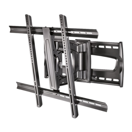
Thank you for choosing the Rocketfish RF-TVMFM03.
The RF-TVMFM03 TV mount is designed to support a
flat-panel TV weighing up to 130 lbs. (58.9 kg).
Package contents
A Right vertical TV bracket (1)
M8 bag
B Left vertical TV bracket (1)
Q M8 × 16 mm screws (4)
C Horizontal TV bracket (2)
R M8 × 40 mm screws (4)
D Arm assembly (1)
S M8 × 60 mm screws (4)
E Wall plate (1)
Hex key bag
M4 bag
T 3/16 in. hex key (1)
C
F M4 × 12 mm screws (4)
Lag bolt bag
M
G M4 × 30 mm screws (4)
U Lag bolt washer (4)
Y
H M4/M5 washers (8)
V 5/16 in. × 2-3/4 in. lag bolt (4)
CM
I
M4/M5 spacers (4)
Bracket hardware
MY
M5 bag
W 9/16 in. × 8/32 in. Phillips head screw (4)
CY
J
M5 × 12 mm screws (4)
X 3/8 in. × 8/32 in. Phillips head screw (1)
CMY
K M5 × 30 mm screws (4)
Cable ties
K
M6 bag
Y 8 in. nylon cable ties (5)
L M6 × 12 mm screws (4)
Cap screws
M M6 × 20 mm screws (4)
Z 5/32 in. hex key (1)
N M6 × 35 mm screws (4)
AA Cap screws (2)
O M6/M8 washers (4)
P M6/M8 spacers (4)
A
B
C
M4 bag
F
G
M4
×
12 mm
M4
×
30 mm
H
I
M4/M5
M4/M5
M5 bag
J
K
D
M5
×
12 mm
M5
×
30 mm
M6 bag
L
M
N
O
M6
×
12 mm
M6
×
20 mm
M6
×
35 mm
M6/M8
M8 bag
Q
R
M8
×
16 mm
M8
×
40 mm
M8
×
60 mm
Hex key bag
Cable ties
T
3/16 in.
Cap screws with hex key
U
V
Lag bolt bag
5/16 in. × 2-3/4 in.
Tools you will need:
•
Stud finder
•
Socket wrench with
•
Awl
1/2 in. socket or
•
Pencil
adjustable wrench
•
Level
•
7/32 in. wood drill bit
•
Tape measure
•
Power drill
•
Phillips screwdriver
V2
FINAL
FOR PRINT
1 Install the TV brackets
Option 1: Installing for a flat mounting surface
1 Align the TV brackets (A and B) with the screw holes on the back of the TV.
2 Place the M4/M5 washers (H) or M6/M8 washers (O) over the holes in the TV brackets that
Note: Intended for use on
align with the screw holes on the back of the TV, then insert the M4 screws (F), M5 screws (J),
wood stud walls with 16 in.
M6 screws (L or M), or M8 screws (Q) through the washers.
or less spacing only.
3 Tighten the screws until they are snug against the TV bracket. Do not over tighten.
Option 2: Installing for an obstructed mounting surface
Note: Use additional washers (H) with M4/M5 hardware only.
1 Place the M4/M5 spacers (I) or M6/M8 spacers (P) and the M4/M5 washers (H) into the
recessed screw holes on the back of the TV.
2 Align the TV brackets (A and B) with the spacers and washers on the back of the TV.
3 Place the M4/M5 washers (H) or M6/M8 washers (O) over the holes in the TV brackets that
align with the screw holes on the back of the TV, then insert the M4 screws (G), M5 screws (K),
M6 screws (N), or M8 screws (R or S) through the washers.
4 Tighten the screws until they are snug against the TV bracket. Do not over tighten.
E
P
M6/M8
Bracket hardware
S
W
X
Y
Z
5/32 in.
AA
2 Add the horizontal bars
1 Slide the horizontal bars (C) through the wire guides on the TV brackets.
2 Secure the bars to the TV brackets using the 9/16 in. × 8/32 in. Phillips head screws (W).
R
or
or
3 Install the wall plate to a wood stud wall
Note: Any material covering the wall must not exceed 5/8 in. (16 mm).
1 Locate the studs. Verify the center of the stud with an awl
or thin nail or use an edge-to-edge stud finder.
2 Level the wall plate (E) and mark the hole locations.
3 Drill pilot hole to a depth of 3 in. using a 7/32 in. diameter drill bit.
4 Align the wall plate (E) with the pilot holes.
5 Place the washers (U) over the holes in the wall plate (E),
insert the lag bolts (V) through the washers, then tighten
the lag bolts only until the washers (U) are pulled firmly
against the wall plate.
CAUTION: Avoid potential
injuries or property damage!
DO NOT over-tighten
the lag bolts (V).
Wall
10-1/5 in.
7 in.
TV
TV shifts 7 in. from the home position to
full extension.
or
or
or
<5/8 in.
16 in .
(75 mm)
3 in.
Advertisement

Related Manuals for RocketFish RF-TVMFM03


Summary of Contents for RocketFish RF-TVMFM03
- Page 1 16 in. or less spacing only. Thank you for choosing the Rocketfish RF-TVMFM03. The RF-TVMFM03 TV mount is designed to support a flat-panel TV weighing up to 130 lbs. (58.9 kg). Package contents A Right vertical TV bracket (1)
- Page 2 Best Buy Imports, S. de R.L. de C.V. Av. Santa Fe 485, Segundo Piso, Colonia Cruz Manca, Programa Parcial de Desarrollo Santa Fe, Delegación Cuajimalpa, Distrito Federal, México 05349 ROCKETFISH is a trademark of BBY Solutions, Inc. All other products and brand names are trademarks of their respective owners.