Advertisement
Quick Links
Gemini 50-Pin Connector to Flying Leads Cable
CE CABLE: 71-016943-10
White/Violet
Enable
1
White/Gray
Digital Ground
2
Red/Black
Reset
3
+5VDC Output
4
Red 16 AWG
+5VDC Output
5
Digital Ground
6
Black 16 AWG
Digital Ground
7
Black
Step+/CW+/AX+
8
White/Black
Step-/CW-/AX–
9
Red
Dir+/CCW+/BX+
10
White/Red
Dir-/CCW-/BX–
11
Green
ZX+
12
White/Green
ZX–
13
Orange
Encoder Out A+
14
White/Orange
Encoder Out A–
15
Blue
Encoder Out B+
16
White/Blue
Encoder Out B–
17
Yellow
Encoder Out Z+
18
White/Yellow
Encoder Out Z–
19
White/Black/Orange
Digital Ground
20
White/Black/Green
Analog Output A
21
Green/Black
Analog Output B
22
Brown
Analog Input+
23
White/Brown
Analog Input–
24
Yellow/Red
Analog Ground
25
Gray/Blue
VINref
26
Yellow/Green
CNTRL-P
27
Gray/Orange
Input 1
28
Blue/Red
Input 2
29
Blue/Orange
Input Ground
30
Input 3
31
Input Ground
32
White/Pink
reserved
33
Orange/Black
reserved
34
White/Black/Blue
reserved
35
Yellow/Blue
Input Ground
36
Yellow/Orange
reserved
37
Blue/Yellow
reserved
38
Violet
reserved
39
White/Black/Red
Input Ground
40
Yellow/Black
reserved
41
White/Black/Yellow
Output Ground
42
Blue/Black
Output 2
43
Green/Red
Output Ground
44
Gray/Green
Output 3
45
Gray/White
Output 4
46
Yellow/White
Output Ground
47
Blue/White
reserved
48
Gray/Brown
reserved
49
Yellow/Brown
reserved
50
Shield
50 Pin Connector
Protective Circuits
Short Circuit Protection
Inrush Current Protection
Drive Overtemperature Protection
Motor Overtemperature Protection
Undervoltage Protection
Overvoltage Protection
Current Foldback
Regeneration Protection
°
°
Operating Temperature
°F)
Storage Temperature:
-40° –
Humidity:
0 – 95%, non-condensing
Shock:
15g, 11msec half sine
Vibration:
10 – 2000 Hz at 2g
Non-CE CABLE: 71-019861-04; -10
1
2
3
*20
4
5
6
Black
7
White/Black
8
Red
9
White/Red
10
Green
11
White/Green
12
Orange
13
White/Orange
14
Blue
15
White/Blue
16
Yellow
17
White/Yellow
18
19
21
22
Brown
23
White/Brown
24
25
*31
26
27
28
*30
Gray
29
Pink
32
33
34
35
36
37
38
39
40
41
42
43
44
45
46
47
48
49
50
* 20, 30,
31 shown out of sequence
Troubleshooting
Commonly used status commands (binary status bits are
numbered 1 to n, from left to right):
TERRLG Error log reports the last 10 error conditions (cleared
with CERRLG).
TAS
General report, including fault conditions.
TASX
Additional report of conditions not covered with TAS.
TCS
If TASX bit #7 or bit #28 is set, you can identify the
cause with TCS.
TINO
Bit #6 indicates status of Enable input ("1" = OK to
enable drive).
TIN
Status of digital inputs, including end-of-travel inputs.
TOUT
Status of digital outputs.
You must configure all motor parameters. Be sure to follow the
drive configuration procedure (see Chapter 2 Installation).
Any fault condition causes the drive to shut down.
The drive can not be enabled (DRIVE1) unless the Enable input
is grounded and the Reset input is not grounded.
Use one of three methods to reset the drive (all command
settings are remembered after reset):
Issue the RESET command.
Momentarily close the Reset input.
Cycle power to the drive.
www.comoso.com
Violet
White
Red
Black
Red
Orange
Black
Blue
Black
White
Red
White
Green
Black
Orange
White
Blue
White
Yellow
White
Green
Brown
Orange
Black
Green
White
Yellow
Brown
Brown
White
Gray
White
Brown
Orange
Yellow
Black
Blue
Brown
Violet
Brown
Violet
Black
Brown
Black
Gray
Brown
Black
Gray
Red
Brown
Drain & Braid
Compumotor Division
Parker Hannifin Corporation
p/n 88-018365-01 B
Quick Reference
Guide
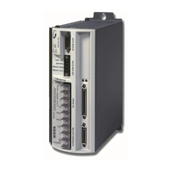
Gemini GV6 Series
Digital Servo
Controller/Drives
(effective February 1, 2002)
Advertisement

Related Manuals for Parker Gemini GV6 Series


Summary of Contents for Parker Gemini GV6 Series
- Page 1 Troubleshooting Short Circuit Protection Commonly used status commands (binary status bits are Inrush Current Protection Gemini GV6 Series numbered 1 to n, from left to right): Drive Overtemperature Protection TERRLG Error log reports the last 10 error conditions (cleared Motor Overtemperature Protection with CERRLG).
- Page 2 www.comoso.com RS-232/485 Connector – Configuration Port LEDs To configure all drive parameters, connect a PC or HPC to this Green/Red Yellow/Green port. Use Motion Planner or Pocket Motion Planner for drive configuration. (Not ASCII protocol.) Gemini GV6 RS-485 Connections RS-232 Connections Digital Servo LED Color: Left...