
Related Manuals for Cisco Aironet 1572EC


Summary of Contents for Cisco Aironet 1572EC
- Page 1 Aironet 1570 Deployment Guide Aironet 1570 Deployment Guide Overview Scope, Objective, and Expectations AP1570 Coverage Recommendations URL Links and Other Resources...
- Page 2 • Maximum radiated RF power allowed by law. • High Density Experience (HDX): ® ™ • Cisco CleanAir 2.0 technology provides integrated spectrum intelligence for a self configuring and self-healing network on 80 MHz channels. • ClientLink 3.0 improves reliability and coverage for legacy 802.11n and 802.11ac data rates.
- Page 3 • Optimized Roaming to allow clients to join the most optimal access point. • Turbo performance which uses Cisco ASIC design to maximize radio performance. • Improved 802.11ac range and performance with 4x4:3 multiple-input multiple-output (MIMO) technology. • 1.3 Gbps (5 GHz) 802.11ac data rates.
- Page 4 • Unified or autonomous operation. Figure 1: Cisco Aironet Outdoor Access Points Figure 2: Performance of Cisco Aironet 1570 Series Access Points...
- Page 5 Figure 3: Comparing AP 1550 Vs. AP 1570 Figure 4: AP 1570 Product Family...
- Page 6 There are three 1572 models: • Cisco Aironet 1572IC—Internal Antennas with cable modem • Cisco Aironet 1572EC—External Antennas with cable modem • Cisco Aironet 1572EAC—External Antenna AC powered Model AP1572 Availability and Compatibility Prime Infrastructure AirOS 8.0.110.0 IOS XE Scope, Objective, and Expectations The Aironet 1570 deployment guide is the first introduction to the AP1572 platform.
- Page 7 • 1572 Antenna Ports • Antenna Options for the AP1572E • New Antenna AIR-ANT2568VG-N • Antenna Options for the AP1572IC • Powering the AP1572 • AP1572 Accessories • AIR-ACC1572-PMK1 (=) • AIR-ACC1572-PMK2 (=) • AIR-ACC1572-PMK3 (=) • AIR-ACC1572-SMK1, 2, 3 •...
- Page 8 The New AP1572 The AP1572 series is an industry leading carrier grade 802.11ac access point (AP). The AP1572 has three models, such as an internal antenna model with cable mode, an external model with cable modem, and an external antenna model. Figure 5: AP 1570 Product ID Nomenclature The AP1572 can operate in the following modes: •...
- Page 9 Aironet 1572IC Product Details The 1572IC has the following features: • Two radios (2.4 GHz and 5 GHz): • 2 GHz: 4x4:3 • 5 GHz: 4x4:3 • Power Options: ◦40 – 90 VAC, 50 – 60 Hz, quasi-square wave, Power over Cable ◦10 –...
- Page 10 The 1572IC has two Gigabit Ethernet ports, the Ethernet port and SFP port. Either the Ethernet port, SFP port, or Cable modem can provide uplink access to the WLC, but only one uplink port can be used for WLC access at a given time. LAG for redundancy is not supported.
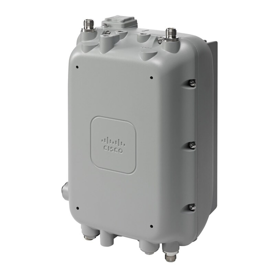
- Page 11 The additional cable attenuation can be added without opening the AP. The shunt and fuse can also be changed. This allows installers easy access. Aironet 1572EC Product Details The 1572EC has the following features: • Two radios (2.4 GHz and 5 GHz): •...
- Page 12 • LTE and WIMAX Signal Rejection (2.1 / 2.3 GHz; 30 dB; 2.5 GHz; 35 dB) • GPS Option The 1572EC has three Gigabit Ethernet ports, the Ethernet port, SFP port, and the PoE-Out port. Either the Ethernet port, SFP port, PoE-Out port or Cable modem can provide uplink access to the WLC, but only one uplink port can be used for WLC access at a given time.
- Page 13 The Console port is located on the side of the AP, covered by a metal cap. The AP MAC address is located on the side of the AP and should be added to the WLC’s MAC Filter list or to a External AAA, for the AP to join a WLC while in Bridge mode. Aironet 1572EAC Product Details The 152EAC has the following features: •...
- Page 14 • 2 GHz: 4x4:3 • 5 GHz: 4x4:3 • Power Options: • 100 – 277 VAC, 50 – 60 Hz • 10 – 16 VDC • UPoE • PoE with AIR-PWRINJ1500-2= • 802.3at PoE Out Capable when powered via AC/DC power •...
-
Page 15: Hardware Components
The Console port is located on the side of the AP, covered by a metal cap. The AP MAC address is located on the side of the AP and should be added to the WLC’s MAC Filter list or to a External AAA, for the AP to join a WLC while in Bridge mode. Hardware Components This section explains the hardware components in AP1572. - Page 16 1572 Antenna Ports The AP1572EC has four antenna ports with N Type connectors, two on the top of the access point (AP) and two on the bottom of the AP. When in Dual band mode, all antenna ports are used creating four transmitters and four receivers with three spatial streams (4x4:3) for both 2.4 GHz and 5 GHz.
- Page 17 Product ID Frequency Band Gain Type Required Quantity (#Ports) AIR-ANT2568VG-N 2.4 / 5 GHz 6 / 8 dBi Omnidirectional 4 (1) AIR-ANT2547VG-N 2.4 / 5 GHz 4 / 7 dBi Omnidirectional 4 (1) AIR-ANT2588P3M-N= 2.4 / 5 GHz 8 / 8 dBi Directional 120x30°...
- Page 18 The antenna patterns are as follows: When the AP1572E with AIR-ANT2568VG-N antennas is configured in the –B Regulatory Domain, Note UNII-1 channels can not be used. Antenna Options for the AP1572IC The 1572IC has internal antennas. Parameter Performance Frequency 2.4 – 2.5 GHz / 5.250 – 5.875 GHz Gain 4 dBi / 6 dBi Polarization...
- Page 19 Powering the AP1572 The AP1572 can be powered via multiple power sources depending on the AP module: • AIR-AP1572EC/AIR-AP1572IC • Power-over-cable (PoC) • External DC Power • AIR-AP1572EAC • AC Power • External DC...
- Page 20 • PoE-IN Model TX/RX:SS Switch Power PWR-INJ1500-2 PoE-Out AC Power DC Power Power over Cable (PoC) 1572I-C 4x4:3 — — — — √ √ 1572E-C 4x4:3 — — √ — √ √ 1572E-AC 4x4:3 UPoE Only √ 802.3at if √ √...
- Page 21 To install the wall / pole mount bracket, perform the following steps: 1 Pull, lock, and tighten bands on the AIR-ACC1572-PMK1 around the pole. 2 Insert four screws into the AP. 3 Slide AP into screw holes on the mounting bracket. 4 Tighten the screws on the AP, securing the AP into the mounting bracket.
- Page 22 • Pole or wall mount option • Band Install Tool needed for installation Configuration Options: • Option 1: Wall Mount, 1 piece, others discarded • Option 2: Vertical only 5-8’, 3 pieces • Option 3: All scenarios, 2-16”, 4 pieces...
- Page 23 AIR-ACC1572-PMK3 (=) Mounting kit for the 1572IC: • Pole diameter: 2-16” (< 20% cases) • Pole or wall mount option • Band Install Tool needed for installation...
- Page 24 Note The AIR-ACC1572-PMK3(=) is recommended for use with the AP1572IC only. AIR-ACC1572-SMK1, 2, 3 There are three cable strand-mounting kits. For more details, see the 1570 Series Hardware Installation Guide. AIR-ANT-GPS-1= This is an add-on GPS module that can be installed on all AP1572 models. This module can be added on to an AP1572 at any time.
- Page 25 (Cisco WLC) >show ap gps location summary AP Name GPS Present Latitude Longitude Altitude GPS location Age ------------------ ----------- ------------ ------------- ------------- ------------------------ 1570-RAP1 37.42034194 -121.91973098 25.10 meters 000 days, 00 h 00 m 19 s 1570-MAP1 37.41970399 -121.92051996 10.00...
- Page 26 Note Antenna Band Mode is only available on the 1572EC and 1572EAC models, with external antennas. Configuring Antenna Band Mode from the WLC GUI To change the Antenna Band Mode, from the WLC GUI, go to the Wireless > Access Point > AP_NAME > Advanced tabs, and then select Dual / Single.
- Page 27 Note are properly configured before changing the Antenna Band Mode. Configuring Antenna Band Mode from the WLC CLI The Antenna Band Mode can be changed via the WLC CLI by issuing the command: (Cisco Controller) >config ap antenna-band-mode <single|dual> <ap_name>...
- Page 28 The Antenna Band mode can be displayed by issuing the command: (Cisco Controller) >show ap config general <AP_NAME> The output will contain many fields, one of which is the Antenna Band Mode: Antenna Band Mode ....... Dual Configuring Antenna Band Mode from the AP CLI Antenna Band Mode can be changed in the AP CLI, by issuing the command: AP#capwap ap ant-band-mode <dual/single>...
- Page 29 If the Master AP is a 1570 and the Slave AP is a 1520 or 1550, the Ethernet cable connects the 1572's Ethernet port to any Ethernet port on the 1552. Serial-Backhaul The 1572 Daisy-chaining feature can be used to provide a serial-backhaul mesh. The Master MAP has a preferred parent selected as the RAP.
- Page 30 High gain directional antenna should be used in typical serial-backhaul deployments. In addition “Preferred Parent” configurations should be used to create serial-backhaul mesh networks. The child AP selects the preferred parent based on the following conditions: • Preferred parent is the best parent. •...
- Page 31 Daisy-chaining between Access Point Models • The Slave AP can be: 1530 / 1550 / 3700P. • PoE-Out is 802.11at (25.5w), 1532E / 3702P, and can be powered directly. • For PoE-Out, the 1572 power source must be AC / DC / or PoC. Configuring a Daisy-Chain There are a few key components to address when configuring a daisy-chaining deployment: •...
- Page 32 AP#capwap ap daisy-chaining <enable/disable> Setting a Preferred Parent for each Serial-Backhaul AP To set up a preferred parent for each serial-backhaul AP, issue the command: (Cisco Controller) >config mesh parent preferred <ap_name> <PARENT_MAC_ADDRESS> An access point’s preferred parent can be seen by issuing:...
- Page 33 Cisco Controller) >show ap config general <ap_name> Then scroll down the Mesh preferred parent entry Mesh preferred parent ......00:24:13:0f:92:00 LED Flashing Sequences The following AP1572 LED behavior notifies users of the status of the Access Point (AP). 1, 2...
- Page 34 1, 2 Color Meaning RF-1 Black Radio turned off or LED off. Steady green Radio is operational; network is good. Steady red Firmware failure. Contact your support organization for assistance. RF-2 Black Radio turned off or LED off. Steady green Radio is operational;...
- Page 35 AP1570 Coverage Recommendations The recommended tool for estimating distance and coverage for the AP1570, is the Coverage and Capacity Calculator. Check the Coverage and Capacity Calculator at http://173.37.206.125/aspnet_client/system_web/2_0_50727/WNG_Coverage_Capacity_Calculator_V2.0_HTML/WNG_Coverage_Capacity_Calculator_V2.0.htm The calculator can be used to estimate AP-to-AP distance. The following table shows a few estimates generated by the calculator for different antenna types.
- Page 36 Reg. Domain Frequency Antenna Gain Max. Distance High Throughput (MCS0LOS) Distance (2.4 GHz: MCS23, 5 GHz: 80 MHz MCS8-3 LOS) 2.4 GHz 3.3 km 200 m 5 GHz 2.7 km 30 m 2.4 GHz 1 km 30 m 5 GHz 1 km 20 m 2.4 GHz...
- Page 37 URL Links and Other Resources This section lists the useful reference materials. AP 1572 Datasheet http://www.cisco.com/c/en/us/products/wireless/aironet-1570-series/datasheet-listing.html Cisco Antenna Reference Guide http://www.cisco.com/c/en/us/products/collateral/wireless/aironet-antennas-accessories/product_data_sheet09186a008008883b.html Why Buy Cisco Brand Antennas http://www.cisco.com/en/US/prod/collateral/wireless/ps5678/ps10981/white_paper_c11-671769.pdf Understanding Antenna Patterns and their Meaning http://www.cisco.com/en/US/prod/collateral/wireless/ps7183/ps469/prod_white_paper0900aecd806a1a3e.html 8.0 Mesh Deployment Guide http://www.cisco.com/c/en/us/td/docs/wireless/technology/mesh/8-0/design/guide/mesh80.html...
- Page 38 © 2014 Cisco Systems, Inc. All rights reserved.
- Page 39 Cisco Systems, Inc. Cisco Systems (USA) Pte. Ltd. Cisco Systems International BV San Jose, CA 95134-1706 Singapore Amsterdam, The Netherlands Cisco has more than 200 offices worldwide. Addresses, phone numbers, and fax numbers are listed on the Cisco Website at www.cisco.com/go/offices.