Table of Contents
Advertisement
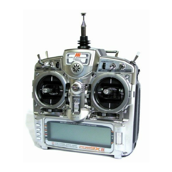
Sailplane – GLID Mode
PCM9X II Transmitter Features (Front)
Flap Trim/Hover Pitch Trim
Throttle Hold/
Mix/Butterfly Switch
Rudder D/R / AUX4 Switch
Elevator D/R
Flap/AUX2 Switch
Flap Lever/
Pitch Trim Lever
Rudder/Elevator Stick
Elevator Trim
Rudder Trim
Power Switch
Menu Buttons
Switch Labels
RUDD D/R / AUX4
T.HOLD / MIX
ELEV D/R
FLAP / AUX2
GEAR
AILE D/R
F.MODE / AUX4 / AUX2
(Spoiler Stick)
TRN / SN ROLL
(Menu Button)
(Left Side Lever)
(Right Side Lever)
Antenna
LCD Display
Transmitter shown with stick mode 1 selected
and switch labels relevant to Glider mode highlighted on multi-function switches
Airplane Menus
RUD D/R
MIX SW
ELE D/R
FLAP SW
GEAR SW
AIL D/R
AUX2 SW
SNAP SW
FLAP LV
AUX3 LV
Switch Naming in the Menus
Neckstrap Attachment
Sailplane Menus
RUD D/R
BTFL SW
ELE D/R
AUX4 SW
MOTO S/W
AIL D/R
FMOD SW
SPOI ST
TIME SW
TIM KEY
FLAP LV
AUX3 LV
1
Aux Trim/
Hover Throttle Trim
Handle
Trainer/Timer Switch
Flight Mode/
AUX4/AUX2 Switch
Aileron D/R
AUX3 Lever
Gear/Motor Switch
Aileron/Spoiler Stick
Spoiler Trim
Aileron Trim
Rolling Selector
Heli Menus
RUD D/R
HOLD SW
ELE D/R
AUX2 SW
GEAR SW
AIL D/R
FMOD SW
Pit.T LEV
AUX3 LEV
Sailplane Section
Advertisement
Table of Contents

Related Manuals for JR PCM9X II


Summary of Contents for JR PCM9X II
-
Page 1: Pcm9X Ii Transmitter Features (Front)
Sailplane – GLID Mode PCM9X II Transmitter Features (Front) Antenna Neckstrap Attachment Flap Trim/Hover Pitch Trim Aux Trim/ Hover Throttle Trim Throttle Hold/ Mix/Butterfly Switch Handle Rudder D/R / AUX4 Switch Trainer/Timer Switch Elevator D/R Flight Mode/ AUX4/AUX2 Switch Flap/AUX2 Switch... - Page 2 Sailplane Section...
-
Page 3: Table Of Contents
Contents – Glider Section PCM9X II Transmitter Features (Front) Sailplane- GLID Mode System Mode GLID Features Function Mode GLID Features System Mode – Functions Specific to GLID mode Device Select Flight Modes Device Select - Activating and Assigning Flight Modes... -
Page 4: Sailplane- Glid Mode
Sailplane- GLID Mode The GLID mode is intended for multi-function Active flight mode digital trims allow in-flight sailplanes. The program software was developed by adjustments of camber, elevator, rudder and aileron. some of the world’s leading sailplane pilots and offers a Trim settings are automatically stored and recalled in level of sophistication not found in any other sailplane each individual flight mode. -
Page 5: System Mode - Functions Specific To Glid Mode
System Mode – Functions Specific to GLID mode System mode contains the foundational programming. are specific to the glider mode. The system functions System mode screens include model name, model that are common to all 3 model types are described in reset, modulation, data transfer, etc.—functions that are the common section at the front of this manual. -
Page 6: Device Select
The PCM9X II offers up to 5 flight winch conditions. modes that include Launch, Land, Cruise, Speed and •... -
Page 7: Device Select - Activating And Assigning Flight Modes
Device Select - Activating and Assigning Flight Modes In the factory default setting, all flight modes are In system mode list rotate the Selector until Device inhibited. Flight modes are activated and assigned to SEL is highlighted. Press the Selector to access the the desired switch position using the SPEED and LAUN Device Select screen. -
Page 8: Activating And Assigning Flight Modes (Continued)
Activating and Assigning Flight Modes (continued) To activate the speed and thermal flight modes, must be in the cruise position. Try selecting the various highlight SPEED and press the Selector to select the flight modes several times while looking at the main info desired switch position. -
Page 9: Motor Function
Motor Function The motor function can be assigned to operate from several different switches, buttons or the throttle stick. AIL D/R Aileron dual rate switch In device select, highlight MOTO and press the Selector ELE D/R Elevator dual rate switch to access the available switches that can be RUD D/R Rudder dual rate switch... -
Page 10: Wing Type
Highlight the desired ACT/INH below the appropriate Activating / Inhibiting Channels channel. Press the Selector to inhibit or activate the channel. Channels 6–9 can be inhibited, allowing them to be used as slave channels, in programmable mixes. Wing Type This screen allows the selection of V-tail, dual flap and, If your sailplane has dual flaps, activate the dual flap when dual flaps are activated, aileron-to-flap trim. -
Page 11: Trim Step
Trim Step The Trim Step function provides for adjusting the Use a fairly coarse setting such as 4–6 when test flying sensitivity of the trim levers. It is useful during and after an aircraft in order to be able to trim the aircraft quickly, initial trimming of the aircraft, in order to trim the aircraft and then use a finer setting such as 3–1 for final quickly at first and then to make very precise... -
Page 12: Function Mode
Function Mode Programs found in the function mode are more the Fail Safe and Trainer functions are covered in the frequently used. Not only are these functions used general section at the front of this manual. during initial setup, but many of these are commonly To enter function modes, turn on the transmitter then adjusted at the field to change/optimize the flight press the ENT button. - Page 13 Flaperon Mix Pg. 19 Programmable Curve Mix Pg. 22 Aileron-to-Rudder Mix Pg. 20 Programmable Mix Pg. 25 Butterfly Mix Pg. 20 Timer Pg. 28 Flap Rate Pg. 21 Servo Monitor Pg. 29 Motor Hold Pg. 21 Sailplane Section...
-
Page 14: D/R & Exp - Dual Rate And Exponential
D/R & EXP – Dual Rate and Exponential Three dual and exponential rates are available and are Devic.SEL function and D/R was set to FM in selectable via flight modes or selected switches. Dual the same function, there will be 3 sets of and Expo rates are independently adjustable in each values displayed for each channel –... -
Page 15: Sub Trim
SUB TRIM Use Sub Trims to fine-tune the alignment of servo 2. Highlight and select the channels where the sub arms. trims must be adjusted. Once a channel is selected, rotate the Selector until the servo arm is in the 1. -
Page 16: Trvl. Adj - Travel Adjust
TRVL. ADJ – Travel Adjust Travel Adjust allows from 0-150% (0 degrees to 60 2. Use the Selector to highlight and select each channel degrees) independent adjustment of servo travel for and adjust the travel in each direction by rotating the each direction of servo travel. -
Page 17: Aileron-To-Flap Mix
Aileron-to-Flap Mix Aileron-to-flap mix causes the flaps to move in unison Note: Two aileron-to-flap mix values are available— with the ailerons. This function gives added roll Pos0 and Pos1. Switches are available at the bottom of response by mixing ailerons to flaps such that the entire the screen that allow the selection of Pos0 or Pos1. -
Page 18: Flight Mode Delay Adjust
Flight Mode Delay Adjust The flight mode delay adjust screen allows a delay of Device Select Pg. 6 and Servo Monitor pg. 29 for more up to 2 seconds to be programmed to each of the 5 details. flight modes. This delay affects the flap, flaperon and To access flight mode delay adjust, in FUNC.LIST elevator (and rudder and aileron if activated) presets rotate the Selector until FM Delay is highlighted. -
Page 19: Flaperon Mix
Flaperon Mix Important: Flaperon mix values are based on a pilots prefer the neutral position to be in the lever up percentage of the value programmed in Flap Rate (see position. (Offset +170) page 21). If no values are programmed in flap rate To access flaperon mix, in FUNC.LIST rotate the (default setting) then flaperon mix values will have no Selector until Flaprn MX is highlighted. -
Page 20: Aileron-To-Rudder Mix
Aileron-to-Rudder Mix Aileron-to-rudder mix causes the rudder to move in corresponding to the flight mode and desired direction unison with ailerons. It is utilized to reduce adverse yaw and then press the Selector to access that value. With and to improve the turning/ handling characteristics. the flight mode switch in the corresponding mode, give Aileron-to-rudder mix values can be independently an aileron command and rotate the Selector to achieve... -
Page 21: Flap Rate
Flap Rate Flap Rate allows the independent up and down To access Flap Rate in FUNC.LIST rotate the Selector adjustment of flaps with the lever that camber mix is until FLAP RATE is highlighted. Press the Selector to assigned to (flap lever on the left or Aux. 3 lever on the access the Flap Rate menu. -
Page 22: Prog Mix - Programmable Mixers
PROG MIX – Programmable Mixers The PCM9X II System provides 2 Multi-Point reacts to the Master is called the Slave channel. Mixing programmable mixers (PROG.MIX1 & PROG.MIX2) occurs when the pilot provides an input to the Master and 4 Standard programmable mixers (PROG.MIX3 - channel by moving a stick, switch, or lever. -
Page 23: Master Channel - (Multi-Point Mixer)
Master Channel - (Multi-Point Mixer) This is the Master channel that receives input from the channels can also be used as a Master while bypassing pilot. The Master channel is selected by highlighting any Dual Rate and Exponential settings that may be and selecting this parameter to obtain a list of channels associated with them. - Page 24 Master Channel - (Multi-Point Mixer) continued Cursor - (Multi-Point Mixer) Slave Channel Position - (Multi-Point Mixer) The cursor shows the current Master channel position. When the Master channel is deflected fully in one The Slave servo position next to OUT at the bottom left direction, the cursor is to the extreme left over Point-0, of the display is expressed in values from -100 to +100, when it is at neutral it is in the center over Point-3 and...
-
Page 25: Standard Programmable Mixer - (Std. Prog Mixer)
Standard Programmable Mixer - (Std. Prog Mixer) The PCM9X II has 4 standard programmable mixers percentages to accommodate movement of the Master that allow for linear mixing of a Master channel to a channel in both directions. This is shown in the Slave channel. -
Page 26: Prog Mix - Programmable Mixers (Continued)
PROG MIX - Programmable Mixers (continued) the solid bar moves between the top and bottom line. If Direction - (Std. Prog Mixer) for example, the switch is set so that Pos0 percentages are in effect and the master channel is moved below Each standard programmable mixer has two positions - the Offset, the solid bar will be on the lower line which Pos0 and Pos1 and each position has 2 percentages... -
Page 27: Prog Mix - Programmable Mixers (Continued)
PROG MIX - Programmable Mixers (continued) percentages for Pos0 and the upper and lower Offset - (Std. Prog Mixer) percentages of Pos1. The amount of mix and actual direction that the slave moves is determined by the The Offset parameter defines the position of the Master Pos0/Pos1 values. -
Page 28: Timer
Timer The PCM9X II contains a Timer System that contains 2. To configure a timer as a Countdown timer, highlight three timers. One is an integrated timer that keeps track and select Timer in the FUNCTION LIST to obtain of total TX-on time for the model and it is displayed on the Timer display. -
Page 29: Servo Monitor
Servo Monitor Sophisticated internal programming allows preset trim Selector again to access the camber digital preset positions for the elevator, flaps and flaperons (and the screen. To adjust the presets, move the flight mode aileron and rudder). The system can remain active in switch to the launch mode (up) position. - Page 30 Sailplane Section...
- Page 31 Sailplane Section...
- Page 32 Sailplane Section...