Pioneer XV-DV575 Service Manual
Dvd/cd receiver
Hide thumbs
Also See for XV-DV575:
- Operating instructions manual (102 pages) ,
- Operating instructions manual (106 pages) ,
- Service manual (94 pages)
Table of Contents
Advertisement
DVD/CD RECEIVER
XV-DV575
XV-DV580
XV-DV385K
XV-DV395K
THIS MANUAL IS APPLICABLE TO THE FOLLOWING MODEL(S) AND TYPE(S).
Model
Type
XV-DV575
WYXJ5
XV-DV580
WYXJ5
XV-DV580
WVXJ5
XV-DV385K
WSXJ5
XV-DV395K
WSXJ5
For details, refer to "Important Check Points for good servicing".
PIONEER CORPORATION
PIONEER ELECTRONICS (USA) INC. P.O. Box 1760, Long Beach, CA 90801-1760, U.S.A.
PIONEER EUROPE NV Haven 1087, Keetberglaan 1, 9120 Melsele, Belgium
PIONEER ELECTRONICS ASIACENTRE PTE. LTD. 253 Alexandra Road, #04-01, Singapore 159936
PIONEER CORPORATION
Power Requirement
AC 220 V to 240 V
AC 220 V to 240 V
AC 220 V to 240 V
AC 220 V to 240 V
AC 220 V to 240 V
4-1, Meguro 1-chome, Meguro-ku, Tokyo 153-8654, Japan
2008
XV-DV575
Regional restriction
codes
(Region No.)
2
2
2
5
5
T-IZK APR.
ORDER NO.
RRV3748
Remarks
2008 Printed in Japan
Advertisement
Table of Contents

Related Manuals for Pioneer XV-DV575


Summary of Contents for Pioneer XV-DV575
- Page 1 PIONEER CORPORATION 4-1, Meguro 1-chome, Meguro-ku, Tokyo 153-8654, Japan PIONEER ELECTRONICS (USA) INC. P.O. Box 1760, Long Beach, CA 90801-1760, U.S.A. PIONEER EUROPE NV Haven 1087, Keetberglaan 1, 9120 Melsele, Belgium PIONEER ELECTRONICS ASIACENTRE PTE. LTD. 253 Alexandra Road, #04-01, Singapore 159936...
-
Page 2: Safety Information
LD ON mode in the test mode oscillates with the laser forcibly. 2. When the cover is open, close viewing through the objective lens with the naked eye will cause exposure to the laser beam. ∗ : See page 24. Name label XV-DV575... - Page 3 To protect products from damages or failures during transit, the shipping mode should be set or the shipping screws should be installed before shipment. Please be sure to follow this method especially if it is specified in this manual. XV-DV575...
-
Page 4: Table Of Contents
10.6 SYSMAIN ASSY (4/5) ..............................60 10.7 SYSMAIN ASSY (5/5) ..............................62 10.8 COMPLEX ASSY ................................64 10.9 EUROSCART ASSY ..............................66 10.10 DSP ASSY (XV-DV575, XV-DV580 ONLY) .......................68 10.11 POWER SUPPLY UNIT.............................70 10.12 WAVEFORMS ................................72 11. PCB CONNECTION DIAGRAM ............................74 11.1 EUROSCART ASSY ..............................75 11.2 08 DVDM ASSY ................................76... -
Page 5: Service Precautions
As a signal to drive the BTL is output from the negative speaker terminal, DO NOT short-circuit between the negative speaker terminal and ground, such as the chassis. Do not short-circuit between the plus speaker terminal and ground, such as the chassis, too. Negative Speaker Terminal Do not short-circuit Ground (Chassis) XV-DV575... -
Page 6: When Replacing Dvd Mecha Assy
1. Slide the Rack Loading (White) toward the arrow direction by using a minus driver to release the lock. (Refer to Fig. 1) 2. Manually open the Tray. NOTE: Please strongly pushing Rack Loading (White) to release the lock because the tray doesn't go out easily. Minus screwdriver Rack Loading (White) Tray open Bottom view Fig. 1 XV-DV575... -
Page 7: Specifications
..420 mm (W) x 60 mm (H) x 339 mm (D) • This unit will play DVD+R/+RW discs. Weight (XV-DV575, XV-DV580)..2.8 kg • is a trademark of FUJIFILM Corporation. -
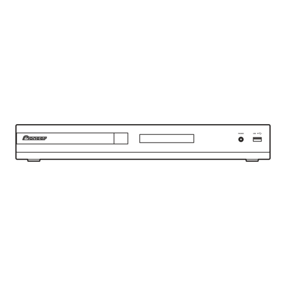
Page 8: Panel Facilities
2.2 PANEL FACILITIES Front panel COMPATIBLE XV-DV575 XV-DV580 XV-DV385K XV-DV395K OPEN/CLOSE 11 USB interface Opens/closes the disc tray. Connect a USB device for playback (see USB playback). DVD/CD Selects the DVD/CD function and starts/ pauses/resumes playback. Stops playback. Selects the USB function and starts/pauses playback. - Page 9 – Lights when a broadcast is being received. – Lights when a stereo FM broadcast is being received in auto stereo mode. – Lights when FM mono reception is selected. – Lights when in one of the RDS display or search modes. XV-DV575...
- Page 10 SURROUND – Selects a Surround mode EXT PWR V. ENH FRT. SURR/EXT PWR or switches to stereo playback. MP3 EXP/V. ENH ADVANCED – Selects a Pioneer original (XV-DV385K) surround mode. (XV-DV395K) LINE OUT TV CONTROL SOUND – Accesses the sound menu to SLEEP adjust the tone, bass and treble, etc.
-
Page 11: Basic Items For Service
Sound interrupted Mottled color Cleaning Before shipping out the product, be sure to clean the following positions by using the prescribed cleaning tools: Position to be cleaned Cleaning tools Pickup lens Cleaning liquid : GEM1004 Cleaning paper : GED-008 XV-DV575... -
Page 12: Pcb Locations
3.2 PCB LOCATIONS XV-DV575, XV-DV580 ONLY FM/AM TUNER UNIT EUROSCART ASSY DSP ASSY SYSMAIN ASSY 08 DVDM ASSY POWER SUPPLY UNIT DVD MECHA ASSY COMPLEX ASSY NOTES: Parts marked by “NSP” are generally unavailable because they are not in our Master Spare Parts List. -
Page 13: Jigs List
SDS1177 (SR/GRAY), SDS6050 (C/GREEN) Lubricants and Glues list Name Lubricants and Glues Remarks Daifree GEM1036 (ZLX-ME413A) Refer to "9.3 DVD MECHA ASSY" Refer to "9.3 DVD MECHA ASSY" Lubricating oil GYA1001 (ZLB-PN397B) Grease GEM1018 Refer to "9.3 DVD MECHA ASSY" XV-DV575... -
Page 14: Block Diagram
CN951 CN5532 XKP3053- XKM3004- SYSMAIN ASSY DEC_MUTE DEC_MUTE DSP DI DSP DI DSP DO DSP DO (XV-DV575 : XWM3392) DSP CK DSP CK DSP RST DSP RST (XV-DV580 : XWM3395) DSP SS DSP SS BUSY BUSY DSP HREQ DSP HREQ... - Page 15 (XV-DV385K, XV-395K) 27P FFC (XV-DV575, XV-DV580) AUDIO OUT (XDD3260-) (XDD3261-) LINEOUT_R CN3111 PG13KA-F07 AKB7114 RUS,EU CN3211 COMPLEX ASSY AKE7121 R SUPPLY UNIT (XV-DV575, XV-DV580 : XWM3429) (XV-DV385K, XV-DV395K : XWM3428) CN3201 6ch SP OUT B2P-VH B2P-VH XDX3067- (XV-DV385K, XV-DV395K) XV-DV575...
-
Page 16: Overall Block Diagram
Y/G , Cb/B , Cr/R Y , Cb , Cr HDMI OUT IC401 Y , C Y , C PWR CONT (from SYST FL DC +/- POWER SUPPLY UNIT VFDP SW10.5V V+10 EV5.0V VE+5 SW5.0V SW6.8V V+6R8 SW 3.3V(B) V+3R3 SW 3.3V(A) XV-DV575... - Page 17 Y , C V+3R3 D2-Terminal (JAPAN model only) DIGTAL OPT IN (DSP model only) PWR CONT (from SYSTEM U-COM) MCACC MIC MCACC (DSP model only) (DSP model only) V+10 VE+5 V+5V V+6R8 DVDPOWER V+3R3 (from SYSTEM U-COM) AC IN XV-DV575...
-
Page 18: Dvd Loader/Decoder Block Diagram
4.3 DVD LOADER/DECODER BLOCK DIAGRAM XV-DV575... -
Page 19: Diagnosis
Assy. If the voltage is 0.4 V or higher, the 780-nm LD is degraded. 08 DVDM ASSY SIDE A C309 Q305 Q304 R154 R313 R326 R326 R322 C372 R322 UP SIDE L308 Q307 C140 CONTACT SIDE CONTACT CN102 CN104 SIDE XV-DV575... -
Page 20: Dvd Trouble Shooting
08 DVDM Assy displayed on the monitor Check the video signal path between DVD IC (08 DVDM Assy IC201) Video circuit after DVD IC (The FL display lights. The and video-out terminal (see the block diagram) (IC201) mechanism works.) XV-DV575... - Page 21 RGB video signal (IC401-pin 16, pin 18, pin 20) Check the waveform (ALCK: IC201-pin 231), (ALRCK: IC201-pin 227), No sound 08 DVDM Assy (ABCK : IC201-pin 230), (ASDATA0/1/2: IC201-pin 226/225/223). (Picture is normal) DVD IC (IC201) Check the waveform (ASPDIF: IC201-pin 215) XV-DV575...
-
Page 22: Circuit Description Of Digital Amp Section
SD_CD (pin 24) => L IC3401 OTW (pin 25) => L Output LPF section The carrier elements, high-frequency signals that are unnecessary for these speakers, are eliminated. The signals passed through the LPF will become sine-wave signals, as shown in the figure above. XV-DV575... -
Page 23: Specifications Of Protection Circuits For Digital Amp Section
5. Process when the protection circuits are activated The unit is shut down within 30 ms after abnormality detection then the volume level is set to 0. The unit can be turned on immediately after the shutdown. XV-DV575... -
Page 24: Service Mode
: Press the [TEST] and [4] keys in order, and turn on the laser diode (780 nm). 3 Release the Test mode • Turn off the power. • Press the [ESC] key of the remote control unit and reset it. XV-DV575... -
Page 25: Display Specifications Of The Test Mode
: [NTSC] PAL system : [PAL] Automatic setting : [AUTO] Scart terminal output [SK – * *] (Display only the WY model which can do the output setting of scart terminal.) VIDEO : [00] S-VIDEO : [01] : [02] XV-DV575... -
Page 26: Functional Specifications Of The Shortcut Key
Region confirmation mode (ESC + A.MON [Test mode remote control unit] + "1"-"6" [Test mode remote control unit] keys) After you press the A.MON key while holding the ESC key pressed and then input the region number, if the number is different from that set in the unit, an error message is displayed, and the tray opens. XV-DV575... -
Page 27: Specifications Of Model Information Display
Display it according to model information set from the FL controller. 2 Region No. 3 Part number 4 ROM version 5 Flash size 6 FL controller version 7 CHIP VERSION 9 Remote control code a Key code of Main unit XV-DV575... -
Page 28: Functional Specifications Of The Service Mode
""e -2 : NG 7.0e -4 : NG 3 EDC/ID error history (ID Address, EDC/ID errors, last eight errors) Note: ∗ Error of AV1 is not supported in this player. Indication plan contents Character in bold : Item name : Information display XV-DV575... -
Page 29: Service Test Mode
S E R LINE1 (Digital input for Japan and IBD model, SCART for Europe) S E R LINE(2) S E R (Analog input for Japan and IBD model, digital for Europe) LINE(3) S E R (Europe only, analog input) XV-DV575... - Page 30 3. The XSD SHUTDOWN line has either short to ground or disconnected somewhere between the faulty digital amp IC and system microP (PDC175A, PDC176A). • The error is mainly caused by the short circuit at the POWER SUPPLY Unit . • The error will also occur when V+BSW is too low. XV-DV575...
- Page 31 Approx. 3 seconds later POWER ON TIME 6. DSP Error Display (for models with DSP only) • During POWER ON, you can switch between DSP error display <=> Normal display when the SOUND key on the remote control is pressed. XV-DV575...
-
Page 32: Display Specifications Of Dsp Error
DSP error message mode Press "SOUND" button in service test mode to show DSP error message displays. Press "SOUND" again to select normal service test mode. This means that the usual function of "SOUND" is not effective in the service test mode. XV-DV575... -
Page 33: Disassembly
1. Slide the rack, loading (White) toward the arrow direction by using a minus screwdriver to release the lock. 2. Manually open the tray. NOTE: Please strongly pushing rack, loading (White) to release the lock because the tray doesn't go out easily. Minus screwdriver Rack, loading (White) Tray open Bottom view XV-DV575... - Page 34 Front Panel Section Remove the two screws. Unhook the five hooks. Bottom view Note A: Do not use an electric screwdriver. If the screws are over-tightened, the screw threads may be damaged. Remove the front panel section. Front panel section XV-DV575...
- Page 35 Note: After replacement, connect the flexible cable, then remove the soldered joint (open). Disconnect the three flexible cables. CN966 CN964 CN965 08 DVDM Assy Rear view Rear view Remove the four screws. Remove the DVD MECHA Assy. DVD MECHA Assy XV-DV575...
- Page 36 Double sided tape (ZTB-500-10) Length: 15 mm Flexible cable for PICKUP Flexible cable Length: 50 mm Bottom view Bottom view Double sided tape (ZTB-500-10) Length: 20 mm Flexible cable for LOADING Flexible cable for FEED Right view Right view XV-DV575...
- Page 37 Loading Motor Insulator (R) LOADING MOTOR PCB Assy TRAVERSE Assy • Screw Torque: 2.5 ± 0.3 kgf•cm (Screw 1) • Screw Torque: 1.0 ± 0.3 kgf•cm (Screw 2) • Screw Torque: 2.0 ± 0.3 kgf•cm Fig. 2-A Fig. 3-A XV-DV575...
- Page 38 3 supports 1. between A and B. Fig. 3-D 2. Remove the Plate Clamper, Magnet Clamper and Clamper. Check Hook Check Hook Plate Clamper Magnet Clamper Main Frame LOADING MOTOR PCB Assy Check Hook Fig. 3-E Clamper Fig. 5-A XV-DV575...
- Page 39 6. Remove the SW PCB Assy. 7. Remove the screw 4. 8. Remove the Gear Feed. 9. Remove the 2 screws 5. Safety surface for pressing of the insert. 10. Remove the Feed Motor. Fig. 7-C 11. Remove the Gear Motor. XV-DV575...
- Page 40 SW PCB Assy ~ FEED MOTOR ~ WHITE (4) BROWN (3) ~ SPINDLE MOTOR ~ YELLOW (2) GREEN (1) Fig. 7-D TRAVERSE Assy Check Hook • Loosen the wire in the direcion of the arrow. Fig. 7-E XV-DV575...
-
Page 41: Each Setting And Adjustment
ID number. 0 0 0 0 0 0 0 0 1 Note: If you press the PLAY button before inputting a 9-digit ID <PLAY> Enter number, the unit returns to Step 2 without doing anything else. Input ID Number ! XV-DV575... - Page 42 (The STOP key is not accepted after all 9 digits have been entered.) [Player's ID Number Setting] ID Number ? 0 0 0 0 0 0 0 0 1 Compare 0 0 0 0 0 0 0 0 1 <PLAY> Enter <STOP> Memory Clear Input ID Number ! XV-DV575...
- Page 43 (If the DVD DATA DISC has already been loaded, the unit does If the data cannot be read from the disc, the unit will be exited not start reading the data. In this case, open then close the ID Data Input Mode and proceed to the display of “Pioneer” tray.) logo.
-
Page 44: Exploded Views And Parts List
Screws adjacent to b mark on product are used for disassembly. For the applying amount of lubricants or glue, follow the instructions in this manual. (In the case of no amount instructions, apply as you think it appropriate.) 9.1 PACKING SECTION XV-DV575/WYXJ5, XV-DV580/WYXJ5, XV-DV385K/WSXJ5, XV-DV395K/WSXJ5 for XV-DV580/WVXJ5 XV-DV575/WYXJ5,... - Page 45 (German, Italian) Operating Instructions See Contrast table (2) (Dutch, Spanish) Operating Instructions See Contrast table (2) (English) (2) CONTRAST TABLE XV-DV575/WYXJ5, XV-DV580/WYXJ5, WVXJ5, XV-DV385K/WSXJ5 and XV-DV395K/WSXJ5 are constructed the same except for the following: XV-DV575 XV-DV580 XV-DV580 XV-DV385K XV-DV395K Mark No.
-
Page 46: Exterior Section
9.2 EXTERIOR SECTION Part No. 21 (Heat sink WHTS) should be replaced each time a new IC (08 DVDM ASSY IC201) is being replaced. XV-DV575, XV-DV580 only XV-DV575, XV-DV580 only XV-DV385K, XV-DV395K only XV-DV575, XV-DV580 only XV-DV385K, XV-DV395K only Refer to "9.3 DVD MECHA ASSY". - Page 47 Radiation Plate XNG3183 NSP 24 Spacer AEB7092 NSP 25 Guide Sheet XAK3603 (2) CONTRAST TABLE XV-DV575/WYXJ5, XV-DV580/WYXJ5, WVXJ5, XV-DV385K/WSXJ5 and XV-DV395K/WSXJ5 are constructed the same except for the following: XV-DV575 XV-DV580 XV-DV580 XV-DV385K XV-DV395K Mark No. Symbol and Description /WYXJ5...
-
Page 48: Dvd Mecha Assy
08 DVDM Assy CN965 Do not replace the parts. Because, minute adjustments are needed if this condition is disassembled further more. If the repair is needed, replace the DVD MECHA Assy. Grease GEM1018 PCB640 08 DVDM Assy CN964 (SW PCB Assy) XV-DV575... - Page 49 Screw, Tap tite (P)(2.6 x 8) 811022680U Screw, T-tite (B)(M1.7 x 5.0 P3) 813381750U Screw, Pan (M1.7 x 2.3 P3) 814011723U Screw, Tap tite (P)(2 x 8) 816112080U Screw, Pan (M1.7 x 3 P3) 814011730U Screw, Gear Feed 92P700007A XV-DV575...
-
Page 50: Schematic Diagram
L761 1 L1S USBP S-24CS64A0I 4 L2S USBN R762 VTH1047-A CN953 V+3D V+5V (RF) : RF SIGNAL ROUTE GNDD V+3D : FOCUS SERVO LOOP LINE R284 : TRACKING SERVO LOOP LINE R285 : STEPPING SERVO LOOP LINE GNDD GNDD XV-DV575... - Page 51 (S_C) DOWNLOAD : VIDEO SIGNAL ROUTE (S_C) V+3R3 R629 (R/Cr) : VIDEO SIGNAL ROUTE (R/Cr) (G/Y) R628 : VIDEO SIGNAL ROUTE (G/Y) SDATA (B/Cb) : VIDEO SIGNAL ROUTE (B/Cb) IC601 TC7SH08FUS1 (AD) : AUDIO DATA SIGNAL ROUTE GNDD GNDD XV-DV575...
-
Page 52: Dvdm Assy (2/2)
MM1758XF I/XP GNDD G_CY V+5V Q401 GNDD GNDD EXTRA VIDEO OUT IC451 C453 C452 GNDD B_CB VCC1 VCC2 C464 COUT MUTE1 MODE2 C465 VOUT MODED1 VSAG C466 GNDD GND2 C454 R_CR BIAS YOUT C455 GND1 YSAG GNDD GNDD VIDEO XV-DV575... - Page 53 GNDD R476 B/GNDD C476 GNDD A-Side GNDD (C/V) : VIDEO SIGNAL ROUTE(C/V) (S_Y) : VIDEO SIGNAL ROUTE (S_Y) (S_C) : VIDEO SIGNAL ROUTE (S_C) : VIDEO SIGNAL ROUTE (R) : VIDEO SIGNAL ROUTE (G) : VIDEO SIGNAL ROUTE (B) XV-DV575...
-
Page 54: Sysmain Assy (1/5)
0.01 R5565 (XV-DV385K, XV-DV395K) RDSPOW VDET R5564 R5518 R5517 KEY1 EU,KU,J, PDC175A/A8 R5562 KEY2 TXODATA IBD(DSP) LC875BJ0A RAB4C221J DIRERR TXCLK (XV-DV575, XV-DV580) C5521 EEP_SK PCONFIG R5557 C5522 R5521 XPROTECT 0.01 R5522 RAB4C221J EEP_DO DSPDI GNDD EEP_CS DSPDO RAB4C221J C5555 DSPCK VSS2 0.1/16... - Page 55 (DTC114EUA) DATA SELECTOR SW3.3V(B) 2SC4154(BFG) (2SC4081(QR)) SW3.3V(A) GNDD Pwr-ctr FLDC- GNDD GNDD FLDC+ VFDP FL DC- FL DC+ -25.5V DVDPOWER R1001 STBY STBY CHASSIS_GND GNDM GNDD OPT IN (DIGITAL OPT IN) JA4602 GP1FAV51RKBF L4603 CTF1379- R4609 XV-DV575, XV-DV580 GNDD XV-DV575...
-
Page 56: Sysmain Assy (2/5)
STBY (AD) BCKO VREF SCLK 10/50 2-B1 Q4005 (2/2) LRCKO D4903 D4902 HN1A01FU(YGR) LRCLK 2-B1 R4010 UDZS3R9(B) UDZS3R9(B) LINE_IN_L XV-DV575, 2-B1 XV-DV580 VREF C4012 R4012 LINE_IN_R 2-B1 10/50 RECMUTE C4015 R4015 2-B1 VREF VREF 10/50 VE+5 GNDD R4020 R4019 C4016... - Page 57 C4025 R4023 AINR CKS0 AINL CKS2 10/50 (AD) CKS1 R4048 VREF VCOM 1.8k ADBCK IC4002 AGND SCLK NJM2872BF25 ADMCK0 XV-DV575, V+3R3 MCLK Vout XV-DV580 ADLRCK R4045 LRCK R4057 STBY ADDATA DGND SDTO to DIR R4058 R4049 XV-DV575, RAB4C101J-T XV-DV580 GNDD...
-
Page 58: Sysmain Assy (3/5)
10.5 SYSMAIN ASSY (3/5) V+5V V+6R8 3R3V V+6R8 3R3V USB POWER CONTROL XFLAG V+6R8 V+6R8 USBPOWER R9000 V+5USB GNDM XV-DV575, XV-DV580 IC781 GNDM XV-DV385K, XV-DV395K STBY NJM2845DL1-05 GNDD GNDM L772 R772 GNDD ATL7002- 100k R9000 XFLAG DOUT DOUT R771 GNDD... - Page 59 COMPOSITE VIDEO C421 1000/6.3 OUTPUT STBY SQUEEZE GNDD VSEL1 VE+5 V+10 CN451 VE+5 9604S-23C VSEL1 SQEEZE V+10 TVOUT_R LINE_OUT_R TVOUT_L LINE_OUT_L TVMUTE SCART_R SCART_R Q491 XTVMUTE RT1N241M (DTC124EUA) SCART_L SCART_L VSEL2 VSEL2 from u-com 81p DVDPOWER DVDPOWER GNDD CN967 XV-DV575...
-
Page 60: Sysmain Assy (4/5)
PLL_FLT_RET PLL_FLTM PLL_FLTP R3103 AVSS AVSS VRD_PLL R3113 AVSS_PLL C3109 IC3131 1000p/50 AVDD_PLL TAS5508BPAG VBGAP GNDD GNDA XRST /RESET XHPSEL /HP_SEL XPDN /PDN XMUTE /MUTE R3104 V+3R3 DVDD DVSS R3105 19 20 21 STBY X3101 ASS7062 13.5MHz R3106 GNDD XV-DV575... - Page 61 STBY 27 28 29 30 V+5V resistor IC3171 NJM78L05UA 2125 size RS1/10S*** R3171 GNDD 3216 size RS1/8S*** 1608 size RS1/16S*** capacitor 2125 size CKSQ** KN3101 1608 size CCSR** VNF1084- GNDD CKSR** CHASSIS_GND STBY (AD) : AUDIO DATA SIGNAL ROUTE XV-DV575...
-
Page 62: Sysmain Assy (5/5)
STBY /SD_AB OUT_D 330p/50 C3311 R3311 R3302 STBY /SD_CD PVDD_D R3301 STBY 0.1/50 XOTW /OTW PVDD_D GREG BST_D GVDD V+BSW FL/RL AMPLIFIER GNDD LAYOUT NOTE : L325X L335X L345X are PCB track inductors approx. 50mm long and 1mm wide XV-DV575... - Page 63 /RESET_CD R3441 ATH7019 OUT_D C3441 R3403 STBY /SD_AB OUT_D 330p/50 C3411 R3411 R3402 STBY /SD_CD PVDD_D YB 2.7 XOTW R3401 STBY 0.1/50 /OTW PVDD_D R3415 GREG BST_D GVDD V+BSW C/SW AMPLIFIER GNDD NOTICE R3211~R3214,R3311~R3314,R3411~R3414 : ACN7148-(2.7 )(SUB:ACN7141-(2.7 )) (2W) XV-DV575...
-
Page 64: Complex Assy
STBY L5901 47/35 LAU220J C5906 C5905 STBY STBY C5904 C5903 43 42 41 37 36 STBY STBY XV-DV385K, GR10 XV-DV395K XV-DV575, SG18 XV-DV580 SG17 C5919 STBY CN5902 CN5901 R5904 IC5901 SG16 9607S-27F 9607S-29F PT6315 C5918 SG15 R5901 FL DRIVER KEY1... - Page 65 C5972 C5978 R5972 0.047/25 1000p STBY L5972 R5980 R5984 CTF1306 R5974 C5979 STBY R5982 R5986 R5988 STBY R5990 L5974 GNDD CTF1306 V5USB JA602 XKB3056 L601 STBY L603 STBY L602 STBY C603 STBY R602 STBY CHASSIS_GND GNDUSB GNDUSB R603 STBY XV-DV575...
-
Page 66: Euroscart Assy
IC472 MM1507XN-TRB C473 CKS3388 CN461 GNDD C474 D474 DAN202U GNDD V+10 SQUEEZE R470 GNDD BLACK R471 Q462 (2/2) Q462 (1/2) RT3WLMM Q461 (1/2) RT3WLMM RT3WLMM R464 R462 4.7k 1.2k Q461 R463 (2/2) RT3WLMM Q472 Q463 4.7k RT1N241M RT1P441M GNDD XV-DV575... - Page 67 BLANK C491 C480 1000/6.3 R478 C492 GNDD NOTES ALL CAPACITORS ARE IN μF UNLESS OTHERWISE SPECIFIED CKSRYB**K50 JQ : CEJQ**M** AL : CEAL**M** AT : CEAT**M** ALL RESISTORS ARE IN Ω RS1/16S***J RS1/10S***J ALL INDUCTORS ARE IN μH LCYA***J2520 XV-DV575...
-
Page 68: Dsp Assy (Xv-Dv575, Xv-Dv580 Only)
10.10 DSP ASSY (XV-DV575, XV-DV580 ONLY) DSP ASSY V1R2 (XV-DV575, XV-DV580 ONLY : AWX8706) LCKO BCKO C852 stby GNDD C851 R851 /HOLD IC851 PDC136A8 R854 stby R855 C833 C831 C829 R856 R857 stby C832 C830 C828 R837 470p 470p RAB4C470J... - Page 69 GNDD L603 QTL1013 C905 R601 FDTI stby BCKO C904 LCKO GNDD C601 stby R906 stby stby R905 stby C907 stby GNDD KN901 GNDD VNE1948 CN901 XKP3088 NOTES: NO INDICATED PARTS IS... CCSRCH*** CKSRYB*** CEVW*** CN5533 RS1/16S*** UNLESS OTHERWISE NOTED XV-DV575...
-
Page 70: Power Supply Unit
10.11 POWER SUPPLY UNIT XV-DV575... - Page 71 POWER SUPPLY UNIT XV-DV575...
-
Page 72: Waveforms
Tray opening IC201 - pin 226, 225, 223 [ASDATA0/1/2] IC401 - pin 20 [CYOUT] V: 0.5 V/div. H: 10 μs/div. V: 1 V/div. H: 500 ns/div. It must be mesured by High-impedance probe. Playing DVD-REF-A1 Tr.2 Cp.19, Progressive output XV-DV575... - Page 73 SYSMAIN ASSY IC3201, IC3301, IC3401 [PWM_M, PWM_P] IC3201, IC3301, IC3401 [OUT_A, B, C, D] V: 1 V/div. H: 2 μsec/div. V: 5 V/div. H: 2 μsec/div. XV-DV575...
-
Page 74: Pcb Connection Diagram
Symbol In PCB Symbol In Schematic Part Name Diagrams Diagrams C E B Capacitor Connector Transistor B C E SIDE A Transistor with resistor B C E Field effect SIDE B P.C.Board Chip Part transistor Resistor array 3-terminal regulator XV-DV575... -
Page 75: Euroscart Assy
11.1 EUROSCART ASSY SIDE A SIDE A EUROSCART ASSY W203 GNDD C471 GNDD C481 W103 VSEL2 W107 W108 W104 GNDD W101 C482 W202 GNDD W204 GNDD JA451 (ANP7569-B) SIDE B SIDE B EUROSCART ASSY Q462 (ANP7569-B) XV-DV575... -
Page 76: Dvdm Assy
R628 R918 R924 R154 R629 R313 C374 R326 R923 R922 Q308 R921 R903 R481 R905 C372 R907 R908 UP SIDE R322 Q307 L308 Q307 C140 R910 R911 CONTACT R919 SIDE R912 R913 R914 CONTACT CN102 C373 CN104 SIDE (ANP7631-A) XV-DV575... - Page 77 R916 R909 R917 IC101 D802 R803 R802 R151 C152 C151 Q802 C112 C111 R114 C102 R805 R111R113 C101 R104 R101 R103 Q801 R304 CONTACT SIDE CN965 CN964 CN966 CONTACT SIDE CONTACT SIDE CN965 CN964 CN966 (ANP7631-A) To DVD LOADER XV-DV575...
-
Page 78: Sysmain Assy
R5597 C1205 7.MDATA R4955 C4961 CN9001 Q1301 6.ACK C4964 Q4951 4.MIC 5.GNDD L4951 C4963 L4952 C5601 3.VDET VFDP D1403 R4953 CN1001 R4954 2.DVDMUTE C4953 C4954 1.NC R4966 C5603 R4968 R1001 D4961 C4967 CN5603 CN9001 CN1001 CN5532 CN968 CN5901 CN951 XV-DV575... - Page 79 Q3604 D3101 Q3901 C3117 C3120 X3101 R3107 R3106 C4952 R3112 R4951 C3101 KN3001 HP_R HP_L R3907 L4951 R3105 L4952 R3905 R4953 R4954 R3151 C4953 C4954 R3104 C3911 R3103 KN1001 R1001 C3108 C3111 C3921 C3922 C3103 C3104 5532 (XNP3130-B) CN951 XV-DV575...
- Page 80 SIDE B SYSMAIN ASSY CN5531 XV-DV575...
- Page 81 SIDE B CN5531 CN5533 CN451 CN5532 CN1001 CN9001 CN5603 (XNP3130-B) XV-DV575...
-
Page 82: Complex Assy
11.4 COMPLEX ASSY SIDE A COMPLEX ASSY CN9001 CN5901 COMPLEX ASSY S5966 S5967 DVD/CD VR3921 OPEN/CLOSE W113 C5913 GNDD W115 V5901 W103 Production Code IC5902 GNDD W106 C5907 SIDE B COMPLEX ASSY XWM3429- XWM3428- CN5901 XV-DV575... - Page 83 SIDE A S5966 S5962 S5965 S5964 S5991 S5963 - VOL JA3921 + VOL DVD/CD JA3922 JA5901 VR3921 ON/OFF STOP JA602 W118 GNDD W108 C3935 W112 [[ G ]] XWM3428- XWM3429- (XNP3131-B) SIDE B Q5973 IC3921 R5977 C5971 R5964 D601 (XNP3131-B) XV-DV575...
-
Page 84: Power Supply Unit
11.5 POWER SUPPLY UNIT SIDE A SIDE A POWER SUPPLY UNIT XV-DV575... - Page 85 SIDE B SIDE B POWER SUPPLY UNIT XV-DV575...
-
Page 86: Dsp Assy (Xv-Dv575, Xv-Dv580 Only)
11.6 DSP ASSY (XV-DV575, XV-DV580 ONLY) SIDE A SIDE B DSP ASSY DSP ASSY R966 (ANP7570-C) (ANP7570-C) XV-DV575... -
Page 87: Pcb Parts List
1..COMPLEX ASSY (XV-DV385K, XV-DV395K) XWM3428 1..08 DVDM ASSY (XV-DV575, XV-DV580) AWM8118 1..08 DVDM ASSY (XV-DV385K, XV-DV395K)AWM8105 1..NHTS JACK ASSY AWM8034 2..EUROSCART ASSY AWU8291 1..DSP ASSY (XV-DV575, XV-DV580 ONLY) AWX8706 1..POWER SUPPLY UNIT XWR3018 1..SYSMAIN ASSY (XV-DV575) XWM3392 1..SYSMAIN ASSY (XV-DV580) XWM3395 1..FM/AM TUNER UNIT AXX7248 1..SYSMAIN ASSY (XV-DV385K) - Page 88 C3932, C3938 Not used CKSRYB104K16 C3936 Not used CKSRYB122K50 C3939 Not used CKSRYB223K16 PCB PARTS LIST FOR XV-DV575/WYXJ5 UNLESS OTHER WISE NOTED Mark No. Description Part No. Mark No. Description Part No. CN 965 05P CONNECTOR VKN1573 08 DVDM ASSY...
- Page 89 D 5933 (A,66,98) DIODE 1SS352 D 5936 (A,74,99) DIODE 1SS352 L 772 (A,124,45) CHIP SOLID INDUCTOR ATL7002 L 1501 (A,93,33) AXIAL INDUCTOR LAU220J SYSMAIN ASSY (XV-DV575) L 3201 (A,284,68) INDUCTORS ATH7019 MISCELLANEOUS L 3202 (A,267,68) INDUCTORS ATH7019 IC 771 (A,121,39) LOAD SWITCHING AAT4618IGV-0.5-1...
- Page 90 R 3338 (A,210,92) RS1/16S1R0J R 3197 (A,189,84) RS1/16S103J R 3341 (A,246,56) RS1/10S180J R 3199 (A,186,88) RS1/16S8R2J R 3342 (A,232,56) RS1/10S180J R 3204 (A,270,31) RS1/16S221J R 3343 (A,242,56) RS1/10S180J R 3205 (A,265,32) RS1/16S103J R 3344 (A,228,56) RS1/10S180J R 3206 (A,261,34) RS1/16S101J XV-DV575...
- Page 91 R 4951 (A,159,17) RS1/16S473J R 3905 (A,213,12) RS1/16S562J R 3906 (A,213,23) RS1/16S562J R 4952 (A,153,16) RS1/16S473J R 3907 (A,213,13) RS1/16S562J R 4955 (A,62,16) RS1/16S182J R 3908 (A,213,21) RS1/16S562J R 5501 (A,85,25) RAB4C221J R 3909 (A,209,11) RS1/16S183J R 5505 (A,86,28) RS1/16S221J XV-DV575...
- Page 92 C 3231 (A,276,83) CFTLA474J50 CAPACITORS C 3232 (A,259,83) CFTLA474J50 C 427 (A,56,92) ELECT. CAPACITOR CEAT102M6R3 C 3233 (A,238,100) CKSRYB104K25 C 771 (A,121,34) CKSQYB105K16 C 3234 (A,240,106) CKSRYB104K25 C 773 (A,121,37) CKSRYB104K16 C 3235 (A,240,100) CKSRYB104K25 C 781 (A,127,42) CEAT100M50 XV-DV575...
- Page 93 CEAT102M25 C 4024 (A,125,59) ELECT. CAPACITOR CEAT470M35 C 3423 (A,218,84) CKSRYB103K50 C 4025 (A,90,89) CEAT100M50 C 3424 (A,201,84) CKSRYB103K50 C 4026 (A,102,89) CEAT100M50 C 4027 (A,116,71) CKSRYB104K16 C 3425 (A,207,84) CKSRYB102K50 C 3426 (A,190,82) CKSRYB102K50 C 4028 (A,111,73) CKSRYB104K16 XV-DV575...
- Page 94 UDZS12(B) C 5715 (A,55,65) CKSRYB103K50 D 4961 (A,50,12) DIODE UDZS3R9(B) C 5716 (A,45,63) CCSRCH561J50 D 4962 (A,50,14) DIODE UDZS3R9(B) C 5719 (A,52,77) CEAT100M50 C 5720 (A,58,61) ELECT. CAPACITOR CEAT470M35 D 5931 (A,78,107) DIODE 1SS352 D 5933 (A,66,98) DIODE 1SS352 XV-DV575...
- Page 95 R 3305 (A,235,32) RS1/16S103J R 3102 (A,229,12) RS1/16S221J R 3306 (A,231,34) RS1/16S101J R 3103 (A,263,10) RS1/16S4R7J R 3307 (A,231,33) RS1/16S473J R 3104 (A,243,11) RAB4C221J R 3308 (A,231,36) RS1/16S472J R 3106 (A,248,17) RS1/16S105J R 3311 (A,245,58) RESISTOR (2.7 OHM) ACN7148 XV-DV575...
- Page 96 R 3443 (A,212,56) RS1/10S180J R 4026 (A,116,66) RS1/16S102J R 4027 (A,91,74) RS1/16S473J R 3444 (A,198,56) RS1/10S180J R 3601 (A,312,85) RAB4C472J R 4039 (A,92,93) RS1/16S153J R 3605 (A,304,85) RS1/16S472J R 4040 (A,103,82) RS1/16S153J R 3606 (A,304,105) RS1/16S472J R 4048 (A,117,92) RS1/16S182J XV-DV575...
- Page 97 R 5562 (A,49,45) RS1/16S221J C 3115 (A,245,26) CKSRYB474K10 R 5564 (A,49,44) RS1/16S221J C 3116 (A,246,26) CKSRYB104K16 R 5565 (A,49,42) RS1/16S221J C 3117 (A,255,25) CEVW100M10 C 3118 (A,231,28) CKSRYB104K16 R 5566 (A,49,40) RAB4C221J C 3119 (A,227,23) CKSRYB104K16 R 5569 (A,91,52) RS1/16S221J XV-DV575...
- Page 98 C 3611 (A,296,90) CCSRCH821J50 C 3327 (A,246,47) CKSRYB104K25 C 3328 (A,227,47) CKSRYB104K25 C 3612 (A,296,100) CCSRCH821J50 C 3331 (A,243,83) CFTLA474J50 C 3621 (A,312,102) CEVW100M25 C 3332 (A,226,83) CFTLA474J50 C 3622 (A,313,95) CEVW100M16 C 3333 (A,222,100) CKSRYB104K25 C 3623 (A,310,97) CKSRYB104K25 XV-DV575...
- Page 99 C 5522 (A,106,41) CKSRYB103K50 R 5901 (B,44,45) RS1/16S221J C 5524 (A,101,44) CEAT100M50 R 5902 (B,39,45) RS1/16S221J R 5903 (B,56,50) RS1/16S221J C 5539 (A,69,57) CKSRYB104K16 R 5904 (B,48,45) RS1/16S823J C 5555 (A,54,48) CKSRYB104K16 R 5951 (B,20,48) RS1/16S470J C 5557 (A,33,42) CKSRYB104K16 XV-DV575...
- Page 100 Q 472 (B,25,67) TRANSISTOR RT1N241M C 489 (B,53,26) CCSRCH470J50 Q 492 (B,80,40) DIGITAL TR(SC-70) RT1P241M C 490 (B,47,26) CCSRCH470J50 Q 493 (B,74,45) TRANSISTOR IMX9 C 491 (B,27,25) CCSRCH470J50 D 471 (B,49,41) DIODE MC2846-11 C 492 (B,40,26) CCSRCH470J50 D 472 (B,43,41) DIODE MC2848-11 XV-DV575...
- Page 101 Mark No. Description Part No. R 827 (B,32,39) RS1/16S0R0J R 828 (B,30,39) RS1/16S103J R 829 (A,35,37) RS1/16S473J DSP ASSY (XV-DV575, XV-DV580) MISCELLANEOUS R 832 (A,41,42) RS1/16S470J R 833 (A,45,45) RS1/16S470J IC 601 (A,87,53) DIR IC AK4117VF R 834 (A,44,48) RS1/16S470J...
- Page 102 C 833 (A,42,52) CKSRYB104K16 C 851 (B,50,48) CKSRYB104K16 C 901 (A,100,37) CKSRYB105K6R3 C 906 (A,104,46) CKSRYB105K6R3 C 951 (B,92,56) CKSRYB104K16 POWER SUPPLY UNIT POWER SUPPLY UNIT has no service part. FM/AM TUNER UNIT FM/AM TUNER UNIT has no service part. XV-DV575...