Table of Contents
Advertisement
Quick Links
HPE ProLiant XL450 Gen10 Server
Maintenance and Service Guide
Abstract
This guide describes identification and maintenance procedures, diagnostic tools,
specifications for hardware components and software for HPE ProLiant servers. This guide is
for an experienced service technician. Hewlett Packard Enterprise assumes you are qualified
in the servicing of computer equipment, trained in recognizing hazards in products, and are
familiar with weight and stability precautions.
Part Number: 881303-001
Published: October 2017
Edition: 1
Advertisement
Table of Contents

Related Manuals for HP ProLiant XL450 Gen10


Summary of Contents for HP ProLiant XL450 Gen10
- Page 1 HPE ProLiant XL450 Gen10 Server Maintenance and Service Guide Abstract This guide describes identification and maintenance procedures, diagnostic tools, specifications for hardware components and software for HPE ProLiant servers. This guide is for an experienced service technician. Hewlett Packard Enterprise assumes you are qualified in the servicing of computer equipment, trained in recognizing hazards in products, and are familiar with weight and stability precautions.
- Page 2 © Copyright 2017 Hewlett Packard Enterprise Development LP Notices The information contained herein is subject to change without notice. The only warranties for Hewlett Packard Enterprise products and services are set forth in the express warranty statements accompanying such products and services. Nothing herein should be construed as constituting an additional warranty. Hewlett Packard Enterprise shall not be liable for technical or editorial errors or omissions contained herein.
-
Page 3: Table Of Contents
Contents Illustrated parts catalog................5 Server system components......................5 Trusted Platform Module spare parts................. 5 DIMM spare parts.......................5 System battery spare part....................6 System board assembly spare part..................6 Processor spare parts......................6 Heatsink spare parts......................7 Server options..........................7 Storage Controller spare parts................... 8 SFF Flash Adapter spare parts.................. - Page 4 UEFI System Utilities........................34 Selecting the boot mode ....................34 Secure Boot........................35 Launching the Embedded UEFI Shell ................36 Intelligent Provisioning........................ 36 HPE Insight Remote Support......................37 USB support..........................37 External USB functionality....................37 HPE Smart Storage Administrator....................37 Component identification..............39 Front panel components......................39 Front panel LEDs and buttons....................
-
Page 5: Illustrated Parts Catalog
Illustrated parts catalog Server system components Hewlett Packard Enterprise continually improves and changes product parts. For complete and current supported parts information, see the Hewlett Packard Enterprise PartSurfer website (http:// www.hpe.com/info/partssurfer). Item Description Trusted Platform Module spare parts on page 5 DIMM spare parts on page 5 System battery spare part on page 6 System board assembly spare part on page 6... -
Page 6: System Battery Spare Part
Description Spare part number 8GB PC4-2666V-R 1Gx8 DIMM 850879-001 16GB PC4-2666V-R 1Gx8 DIMM 868846-001 16GB PC4-2666V 1Rx4 DIMM 850880-001 32GB PC4-2666V-R DIMM 850881-001 64GB PC4-2666V-R DIMM 850882-001 System battery spare part Customer self repair on page 12: mandatory Description Spare part number System battery MC 96 W V3 871264-001 System board assembly spare part... -
Page 7: Heatsink Spare Parts
Description Spare part number Xeon-G 6140 18c 2.3G 140W 874734-001 Xeon-G 6142 16c 2.6G 150W 874733-001 Xeon-P 8164 26c 150W 875729-001 Xeon-G 6148 20c 2.4G 150W 874732-001 Xeon-P 8156 4c 105W 875732-001 Xeon-G 6152 22c 2.1G 140W 874730-001 Xeon-G 6134 8c 130W 875723-001 Xeon-G 6136 12c 875724-001... -
Page 8: Storage Controller Spare Parts
Item Description Storage Controller spare parts on page 8 SFF Flash Adapter spare parts on page 8 Hot-plug SFF drive spare parts on page 8 microSD spare parts on page 11 Cable kit spare parts on page 11 Not shown For more information, see Removal and replacement procedures on page 21. - Page 9 Description Spare part number HPE 600 GB SAS 10K SFF SC DS HDD 872736-001 HPE 600 GB SAS 15K SFF SC 512e DS HDD 870797-001 HPE 900 GB SAS 15K SFF SC DS HDD 870795-001 HPE 900 GB SAS 15K SFF SC 512e DS HDD 870798-001 HPE 1 TB SAS 7.2K SFF SC DS HDD 832984-001...
- Page 10 Description Spare part number HPE 1.92 TB SATA 6G READ INTENSIVE SFF 875657-001 (2.5 in) SC HPE 1.92 TB SATA RI SFF SC DS SSD 878852-001 HPE 1.92 TB SATA MU SFF SC DS SSD 879019-001 HPE 1.92 TB SATA MU SFF SC DS SSD 875867-001 HPE 1.92 TB SATA 6G MU SFF SC DS SSD 872522-001...
-
Page 11: Microsd Spare Parts
Table 5: NVMe solid state drives Description Spare part number HPE 400 GB NVMe x4 MU SFF SCN SSD 765063-001 HPE 400 GB NVMe x4 RI SFF SCN SSD 765067-001 HPE 400 GB NVMe x4 MU SFF SCN DS SSD 875874-001 HPE 400 GB NVMe x4 WI SFF SC SSD 765059-001... -
Page 12: Customer Self Repair
Customer self repair Hewlett Packard Enterprise products are designed with many Customer Self Repair (CSR) parts to minimize repair time and allow for greater flexibility in performing defective parts replacement. If during the diagnosis period Hewlett Packard Enterprise (or Hewlett Packard Enterprise service providers or service partners) identifies that the repair can be accomplished by the use of a CSR part, Hewlett Packard Enterprise will ship that part directly to you for replacement. - Page 13 • Obligatoire—Pièces pour lesquelles la réparation par le client est obligatoire. Si vous demandez à Hewlett Packard Enterprise de remplacer ces pièces, les coûts de déplacement et main d'œuvre du service vous seront facturés. • Facultatif—Pièces pour lesquelles la réparation par le client est facultative. Ces pièces sont également conçues pour permettre au client d'effectuer lui-même la réparation.
- Page 14 un centro di assistenza autorizzato. Tali parti sono identificate da un "No" nel Catalogo illustrato dei componenti. In base alla disponibilità e alla località geografica, le parti CSR vengono spedite con consegna entro il giorno lavorativo seguente. La consegna nel giorno stesso o entro quattro ore è offerta con un supplemento di costo solo in alcune zone.
- Page 15 Ersatzteil in Rechnung stellen. Im Falle von Customer Self Repair kommt Hewlett Packard Enterprise für alle Kosten für die Lieferung und Rücksendung auf und bestimmt den Kurier-/Frachtdienst. Weitere Informationen über das Hewlett Packard Enterprise Customer Self Repair Programm erhalten Sie von Ihrem Servicepartner vor Ort.
- Page 16 Servicio de garantía exclusivo de componentes La garantía limitada de Hewlett Packard Enterprise puede que incluya un servicio de garantía exclusivo de componentes. Según las condiciones de este servicio exclusivo de componentes, Hewlett Packard Enterprise le facilitará los componentes de repuesto sin cargo adicional alguno. Para este servicio de garantía exclusivo de componentes, es obligatoria la sustitución de componentes por parte del usuario (CSR).
- Page 17 Voor de Parts Only garantieservice is vervanging door CSR-onderdelen verplicht. Als u Hewlett Packard Enterprise verzoekt deze onderdelen voor u te vervangen, worden u voor deze service reiskosten en arbeidsloon in rekening gebracht Reparo feito pelo cliente Os produtos da Hewlett Packard Enterprise são projetados com muitas peças para reparo feito pelo cliente (CSR) de modo a minimizar o tempo de reparo e permitir maior flexibilidade na substituição de peças com defeito.
- Page 18 Customer self repair...
- Page 19 Customer self repair...
- Page 20 Customer self repair...
-
Page 21: Removal And Replacement Procedures
Removal and replacement procedures This chapter provides detailed instructions on how to remove and replace component spare parts. Required tools You need T-15 and T-30 Torx screwdrivers for performing procedures listed in this document. Preparation procedures To access some components and perform certain service procedures, you must perform one or more of the following procedures: •... -
Page 22: Power Up The Server
Power up the server Procedure To power up the server, press the Power On/Standby button. Remove the server from the chassis CAUTION: Before removing the server, verify that the server backup LED is not flashing. Procedure 1. Power down the server on page 21. CAUTION: To avoid damage to the server, always support the bottom of the server when removing it from the chassis. -
Page 23: Safety Considerations
Procedure 1. Prepare the server for installation. 2. Install the server. When seated properly, the server will be flush with the front of the chassis and the release lever will close completely without resistance. Safety considerations Before performing service procedures, review all the safety information. Preventing electrostatic discharge To prevent damaging the system, be aware of the precautions you must follow when setting up the system or handling parts. -
Page 24: Symbols On Equipment
Procedure • Avoid hand contact by transporting and storing products in static-safe containers. • Keep electrostatic-sensitive parts in their containers until they arrive at static-free workstations. • Place parts on a grounded surface before removing them from their containers. • Avoid touching pins, leads, or circuitry. -
Page 25: System Warnings And Cautions
System warnings and cautions Before installing a server, be sure that you understand the following warnings and cautions. WARNING: To reduce the risk of electric shock or damage to the equipment: • Do not disable the power cord grounding plug. The grounding plug is an important safety feature. •... -
Page 26: Removing And Replacing An Nvme Drive
For more information, see Hot-plug drive LED definitions on page 41. 2. Back up all data on the drive. 3. Remove the drive. To replace the drive, slide the drive into the bay until it is fully seated, and then close the latch handle to lock the drive in the bay. -
Page 27: Removing And Replacing The Sff Flash Adapter Option
To replace the drive, slide the drive into the bay until it is fully seated, and then close the latch handle to lock the drive in the bay. Removing and replacing the SFF flash adapter option CAUTION: To prevent improper cooling and thermal damage, do not operate the server or the chassis unless all device bays are populated with either a component or a blank. -
Page 28: Removing And Replacing The System Battery
To replace the component, reverse the removal procedure. Removing and replacing the system battery If the server no longer automatically displays the correct date and time, then replace the battery that provides power to the real-time clock. Under normal use, battery life is 5 to 10 years. WARNING: The computer contains an internal lithium manganese dioxide, a vanadium pentoxide, or an alkaline battery pack. -
Page 29: Removing And Replacing A Storage Controller
IMPORTANT: Replacing the system board battery resets the system ROM to its default configuration. After replacing the battery, reconfigure the system through UEFI System Utilities. To replace the component, reverse the removal procedure. For more information about battery replacement or proper disposal, contact an authorized reseller or an authorized service provider. -
Page 30: Removing And Replacing A Heatsink Blank
To replace the component, reverse the removal procedure. Removing and replacing a heatsink blank Procedure 1. Power down the server on page 21. 2. Remove the server from the chassis on page 22. 3. Place the server on a flat, level work surface. 4. -
Page 31: Re-Entering The Server Serial Number And Product Id
Place the server on a flat, level work surface. Remove any components installed in the drive bay: • Remove any drive blanks installed (Removing and replacing a drive blank on page 25). • Remove any SFF drives installed (Removing and replacing an SFF drive on page 25). •... -
Page 32: Hpe Trusted Platform Module 2.0 Gen10 Option
6. Select Product ID. The following warning appears: Warning: The Product ID should ONLY be modified by qualified service personnel. This value should always match the Product ID located on the chassis. 7. Enter the product ID and press the Enter key. 8. -
Page 33: Troubleshooting
Troubleshooting Troubleshooting resources Troubleshooting resources are available for HPE Gen10 server products in the following documents: • Troubleshooting Guide for HPE ProLiant Gen10 servers provides procedures for resolving common problems and comprehensive courses of action for fault isolation and identification, issue resolution, and software maintenance. -
Page 34: Diagnostic Tools
Diagnostic tools Product QuickSpecs For more information about product features, specifications, options, configurations, and compatibility, see the product QuickSpecs on the Hewlett Packard Enterprise website (http://www.hpe.com/info/qs). UEFI System Utilities The UEFI System Utilities is embedded in the system ROM. Its features enable you to perform a wide range of configuration activities, including: •... -
Page 35: Secure Boot
Procedure 1. From the System Utilities screen, select System Configuration > BIOS/Platform Configuration (RBSU) > Boot Options > Boot Mode. 2. Select a setting. • UEFI Mode (default)—Configures the system to boot to a UEFI compatible operating system. • Legacy BIOS Mode—Configures the system to boot to a traditional operating system in Legacy BIOS compatibility mode. -
Page 36: Launching The Embedded Uefi Shell
Launching the Embedded UEFI Shell Use the Embedded UEFI Shell option to launch the Embedded UEFI Shell. The Embedded UEFI Shell is a pre-boot command-line environment for scripting and running UEFI applications, including UEFI boot loaders. The Shell also provides CLI-based commands you can use to obtain system information, and to configure and update the system BIOS. -
Page 37: Hpe Insight Remote Support
• Press F10 from the POST screen. • From the iLO web browser user interface using Always On. Always On allows you to access Intelligent Provisioning without rebooting your server. HPE Insight Remote Support Hewlett Packard Enterprise strongly recommends that you register your device for remote support to enable enhanced delivery of your Hewlett Packard Enterprise warranty, HPE support services, or Hewlett Packard Enterprise contractual support agreement. - Page 38 Array controllers and integrated Smart Array controllers. Some HPE SSA features are only available in the offline environment, such as setting the boot controller and boot volume. • Accessing HPE SSA in the online environment This method requires an administrator to download the HPE SSA executables and install them. You can run HPE SSA online after launching the host operating system.
-
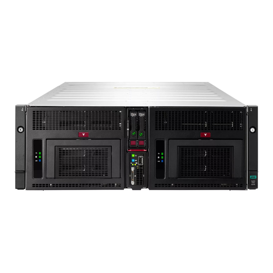
Page 39: Component Identification
Component identification This chapter describes the external and internal server features and components. Front panel components Item Description Drive bay 1 Drive bay 2 Server ejector button iLO Service port Server release lever SUV cable connector Serial label pull tab Component identification... -
Page 40: Front Panel Leds And Buttons
Front panel LEDs and buttons Item Description Status Power On/Standby Solid green = System on button and system Flashing green (1 Hz/cycle per sec) = Performing power on power LED sequence Solid amber = System in standby Off = No power present UID LED/button Solid blue = Activated Flashing blue:... -
Page 41: Hot-Plug Drive Led Definitions
Item Description Status Server health LED Solid green = Normal Flashing green (1 Hz/cycle per sec) = iLO is rebooting Flashing amber = System degraded Flashing red (1 Hz/cycle per sec) = System critical Server backup LED Off = Normal operations. No backup in progress. Flashing white = Backup in progress. -
Page 42: Nvme Ssd Components
NVMe SSD components The NVMe SSD is a PCIe bus device. A device attached to a PCIe bus cannot be removed without allowing the device and bus to complete and cease the signal/traffic flow. CAUTION: Do not remove an NVMe SSD from the drive bay while the Do not remove LED is flashing. The Do not remove LED flashes to indicate that the device is still in use. -
Page 43: Sff Flash Adapter Components And Led Definitions
Item Description Status Power LED Solid green = Do not remove the drive. Drive must be ejected from the PCIe bus prior to removal. Flashing green = Ejection request pending Off = Drive has been ejected Power button Press to request PCIe ejection. Removal request can be denied by the: •... -
Page 44: Server Components
Item Component Description Drive status LED • Off—The drive is not configured by a RAID controller. • Solid green—The drive is a member of one or more logical drives. • Flashing green (4 Hz)—The drive is operating normally and has activity. •... -
Page 45: Dimm Slot Locations
Item Description Processor 2 DIMMs (8) System battery SFF drive cage data cable connector M.2 riser board Front panel I/O board cable connector microSD card slot Front panel I/O board iLO Service Port board DIMM slot locations The arrow points to the front of the server. DIMM slots closest to the processors support NVDIMMs. - Page 46 Position Default Function Off = No function On = ROM reads system configuration as invalid. Reserved — Reserved — Reserved — Reserved — Reserved — Reserved To access the redundant ROM, set S1, S5, and S6 to On. When system maintenance switch S6 is set to the On position, the system is prepared to erase all system configuration settings from both CMOS and NVRAM.
-
Page 47: Cabling
Cabling SUV cable connectors CAUTION: Before disconnecting the SUV cable from the connector, always squeeze the release buttons on the sides of the connector. Failure to do so can result in damage to the equipment. Item Connector Description Serial For trained personnel to connect a null modem serial cable and perform advanced diagnostic procedures For connecting up to two USB 2.0 devices Video... -
Page 48: Controller Cabling
Controller cabling Controller cabling... -
Page 49: Specifications
Specifications Environmental specifications Specification Value Temperature range Operating 10°C to 35°C (50°F to 95°F) Shipping -40°C to 70°C (-40°F to 158°F) Maximum wet bulb temperature 28°C (82.4°F) Relative humidity (noncondensing) Operating 10% to 90% Nonoperating 5% to 95% All temperature ratings shown are for sea level. An altitude derating of 1°C per 300 m (1.8°F per 1,000 ft) to 3,048 m (10,000 ft) is applicable. -
Page 50: Documentation Feedback
Documentation feedback Hewlett Packard Enterprise is committed to providing documentation that meets your needs. To help us improve the documentation, send any errors, suggestions, or comments to Documentation Feedback (docsfeedback@hpe.com). When submitting your feedback, include the document title, part number, edition, and publication date located on the front cover of the document.