Table of Contents
Advertisement
Advertisement
Table of Contents

Related Manuals for HP t620 PLUS


Summary of Contents for HP t620 PLUS
- Page 1 Hardware Reference Guide HP t620 Flexible Series Thin Client...
- Page 2 Microsoft and Windows are U.S. registered trademarks of Microsoft Corporation. The only warranties for HP products and services are set forth in the express warranty statements accompanying such products and services. Nothing herein should be construed as constituting an additional warranty.
-
Page 3: About This Book
About This Book WARNING! Text set off in this manner indicates that failure to follow directions could result in bodily harm or loss of life. CAUTION: Text set off in this manner indicates that failure to follow directions could result in damage to equipment or loss of information. - Page 4 About This Book...
-
Page 5: Table Of Contents
Table of contents 1 Product features ............................. 1 Standard features ..........................1 Front panel components ........................2 Rear panel components ........................3 Using the keyboard ..........................4 Windows Logo Key ......................5 Additional function keys ....................... 5 Special mouse functions ........................5 Serial number location .......................... - Page 6 Appendix B Removing and replacing the battery ..................34 Appendix C Thin client operation ........................38 Routine thin client care ........................38 Supported orientations ........................39 Non-supported orientation ........................41 Appendix D Electrostatic discharge ......................42 Preventing electrostatic damage ......................42 Grounding methods ..........................
-
Page 7: Product Features
Standard features Thank you for purchasing an HP thin client. We hope you have years of use from our thin clients. Our goal is to provide you with award-winning clients that are easy to deploy and manage with the power and reliability you expect. -
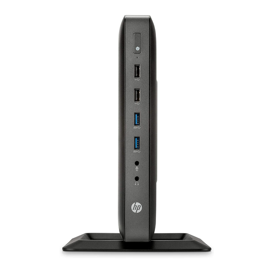
Page 8: Front Panel Components
In the event of damage to the flash storage device due to operation with a disabled write filter or enabled Page File, the damage will not be covered by HP warranty. For more information about write filter usage, see the operating system guide for your thin client available at http://www.hp.com/support/manuals/thinclients. -
Page 9: Rear Panel Components
Dual-mode DisplayPort 1.2 ports (2) (14) Cable lock slot *Available on some models. Refer to the model-specific QuickSpecs at www.hp.com for details. The devices connected at boot up or subsequently disconnected determine which video ports are enabled and which is disabled. -
Page 10: Using The Keyboard
Using the keyboard Caps Lock Activates/deactivates the Caps Lock feature. Scroll Lock Activates/deactivates the Scroll Lock feature. Num Lock Activates/deactivates the Num Lock feature. Ctrl Use in combination with another key; its function depends on the application software you are using. Windows Logo Key 1, 2 Opens the Start menu in Windows... -
Page 11: Windows Logo Key
Windows Logo Key Use the Windows Logo Key in combination with other keys to perform certain functions available in Windows operating systems. Windows Logo Key + Switch between open items. Windows Logo Key + Open My Computer. Windows Logo Key + Search for a file or folder. -
Page 12: Serial Number Location
Serial number location Every thin client includes a unique serial number located as shown in the following illustration. Have this number available when contacting HP customer service for assistance. Chapter 1 Product features... -
Page 13: Hardware Changes
To reduce the risk of serious injury, read the Safety & Comfort Guide. It describes proper workstation, setup, posture, and health and work habits for computer users, and provides important electrical and mechanical safety information. The Safety & Comfort Guide is located on the HP website at http://www.hp.com/ergo. -
Page 14: Connecting The Power Cord
Connecting the power cord Plug the female end of the power cord into the power supply brick (1). Connect the other end of the power cord to an electrical outlet (2). Connect the round end of the power supply cord to the power supply connector on the rear of the computer (3). -
Page 15: Attaching The Stand
Attaching the stand CAUTION: The computer must be operated with the stand attached to ensure proper airflow around the computer. The computer can be used in either a tower or horizontal orientation with the stand included with the computer. Remove/disengage any security devices that prohibit opening the computer. Remove all removable media, such as USB flash drives, from the computer. -
Page 16: Removing And Replacing The Access Panel
NOTE: An optional Quick Release mounting bracket is available from HP for mounting the computer to a wall, desk, or swing arm. When the mounting bracket is used, do not install the computer with the I/O ports oriented towards the ground. - Page 17 Disconnect the power cord from the power outlet, and disconnect any external devices. CAUTION: Regardless of the power-on state, voltage is always present on the system board as long as the system is plugged into an active AC outlet. You must disconnect the power cord to avoid damage to the internal components of the computer.
-
Page 18: Replacing The Access Panel
Replacing the access panel To replace the access panel: Position the access panel (1) on the chassis, approximately 6 mm (.24 in) inside the edge of the chassis. Be sure that the access panel covers the hood sensor, and then slide the panel toward the front of the chassis (2) until it locks into place. - Page 19 Insert the hooks on the right side of the I/O panel (1) into the right side of the back of the chassis, and then press the left side (2) to the chassis until it locks in place. Removing and replacing the access panel...
-
Page 20: Installing Internal Usb Flash Drives
If the computer is an HP t620 PLUS Thin Client, push the fan assembly latch (1) toward the front of the computer and rotate the assembly (2) up and out of the way. - Page 21 Align the USB flash drive with the USB port and press the drive firmly into the port until it is securely seated. If the computer is an HP t620 PLUS Thin Client, rotate the fan assembly down, push the fan assembly latch (1) toward the front of the computer, lower the assembly (2) until it stops, and then release the latch.
-
Page 22: Installing Additional Memory
Replace the computer stand. Reconnect the power cord and turn on the computer. Lock any security devices that were disengaged when the computer cover or access panel was removed. Installing additional memory The computer comes with double data rate 3 synchronous dynamic random access memory (DDR3L- SDRAM) small outline dual inline memory modules (SODIMMs). -
Page 23: Populating Sodimm Sockets
Populating SODIMM sockets There are two SODIMM sockets on the system board. The sockets are labeled DIMM1 and DIMM2. Item Description System Board Label Socket Color SODIMM1 socket DIMM1 Black SODIMM2 socket DIMM2 White The system operates in single-channel mode. NOTE: If both SODIMM sockets are populated with dual-sided SODIMMs, the system memory speed is reduced to 1333 MHz. - Page 24 If the computer is an HP t620 PLUS Thin Client, push the fan assembly latch (1) toward the front of the computer and rotate the assembly (2) up and out of the way.
- Page 25 Locate the memory compartment on the system board. If a fiber NIC is installed, move the cable carefully out of the slot in the memory compartment cover. Remove the two screws and springs (1) securing the memory compartment cover. NOTE: Be sure to retain the two screws and the springs beneath them.
- Page 26 To remove a SODIMM, press outward on the two latches (1) on each side of the SODIMM, rotate the SODIMM up (2), and then pull the SODIMM out of the socket (3). Slide the new SODIMM (1) into the socket at approximately a 30° angle, and then press the SODIMM into the socket (2) so that the latches lock it in place.
- Page 27 (2) with the springs to secure the memory compartment cover. If the computer is an HP t620 PLUS Thin Client, rotate the fan assembly down, push the fan assembly latch (1) toward the front of the computer, lower the assembly (2) until it stops, and then release the latch.
- Page 28 Reconnect the power cord and turn on the computer. Lock any security devices that were disengaged when the computer cover or access panel was removed. The computer automatically recognizes the additional memory when you turn on the computer. Chapter 2 Hardware changes...
-
Page 29: Installing A Half-Height Pci-Express 2.0 Card
Installing a half-height PCI-Express 2.0 card You may install an optional half-height PCI-Express (PCIe) card in the HP t620 PLUS Thin Client. A riser card is installed in this computer by default. WARNING! To reduce the risk of personal injury or equipment damage from electric shock, hot surfaces, or fire, disconnect the power cord from the power outlet and allow the internal system components to cool before you touch them. - Page 30 Locate the slot in the riser card. Slide the expansion slot cover left and remove it. Chapter 2 Hardware changes...
- Page 31 Align the PCIe card connectors with the slot in the riser card and the metal tab at the end of the card with the slot in the chassis. Press the PCIe card firmly into the slot in the riser card until it is securely seated and the tab is in the slot.
-
Page 32: Security
Security The thin client is equipped with a hood sensor. You may also use a cable lock to secure the computer. For an additional layer of security, you may purchase a port cover to prevent unauthorized access to the rear ports. Hood sensor The hood sensor is a combination of hardware and software technology. -
Page 33: Cable Lock
These thin clients are designed to accept a security cable lock. This cable lock prevents unauthorized removal of the thin client, as well as locking devices installed inside the case. To order this option, visit the HP website at http://www.hp.com and search for your specific thin client model. -
Page 34: Mounting The Thin Client
NOTE: When mounting to a thin client, use the 15 mm screws supplied with the HP Quick Release. To use the HP Quick Release: Remove four screws from the right side of the computer. - Page 35 Using four 15 mm screws included in the mounting device kit, attach one side of the HP Quick Release to the thin client as shown in the following illustration. Using four screws included in the mounting device kit, attach the other side of the HP Quick Release to the device to which you will mount the thin client.
- Page 36 (2) on the device on which you want to mount the thin client. An audible 'click' indicates a secure connection. When attached, the HP Quick Release automatically locks in position. You only need to slide the lever to one side to remove the thin client.
-
Page 37: Supported Mounting Options
Supported mounting options The following illustrations demonstrate some of the supported mounting options for the mounting bracket. Mounting the thin client... -
Page 38: Appendix A Specifications
Specifications For the latest specifications or additional specifications on the HP t620 Thin Client or the HP t620 PLUS Thin Client, go to http://www.hp.com/go/ quickspecs/ and search for your specific model to find the model-specific QuickSpecs. Dimensions 40 mm 1.57 in. - Page 39 (max. allowed rate of change is 457m per minute or 1500 ft per minute) Power Supply HP t620 Thin Client HP t620 PLUS Thin Client Operating Voltage Range 100 VAC to 240 VAC 100 VAC to 240 VAC Rated Line Frequency...
-
Page 40: Appendix B Removing And Replacing The Battery
Removing and replacing the battery WARNING! Before removing the side access panel, be sure that the thin client is turned off and the power cord is disconnected from the electrical outlet. To remove and replace the battery: Remove/disengage any security devices that prohibit opening the computer. Remove all removable media, such as USB flash drives, from the computer. - Page 41 If the computer is an HP t620 PLUS Thin Client, perform the following steps: Push the fan assembly latch (1) toward the front of the computer and rotate the assembly (2) up and out of the way. If a PCIe card is installed, remove it carefully.
- Page 42 Carefully press the new battery down to adhere the battery securely to the system board. If the computer is an HP t620 PLUS Thin Client, perform the following steps. If the cables from the PCIe riser card were disconnected in step 7 c, reconnect them.
- Page 43 In order to forward them to recycling or proper disposal, please use the public collection system or return them to HP, an authorized HP partner, or their agents. The Taiwan EPA requires dry battery manufacturing or importing firms, in accordance with Article 15 or the Waste Disposal Act, to indicate the recovery marks on the batteries used in sales, giveaways, or promotions.
-
Page 44: Appendix C Thin Client Operation
In the event of damage to the flash storage device due to operation with a disabled write filter or enabled Page File, the damage will not be covered by HP warranty. For more information about write filter usage, see the operating system guide for your thin client available at http://www.hp.com/support/manuals/thinclients. -
Page 45: Supported Orientations
HP t620 standard (slim) chassis: HP recommends mounting the thin client in the vertical (tower) orientation, with the HP logo right-side up. Mounting in other orientations may result in decreased performance under certain conditions; operating the computer with limited power to prevent overheating is one such condition. - Page 46 Appendix C Thin client operation...
-
Page 47: Non-Supported Orientation
Non-supported orientation HP does not support the following orientations for the thin client. CAUTION: Non-supported placement of thin clients could result in operation failure and/or damage to the devices. CAUTION: Thin clients require proper ventilation to maintain operating temperature. Do not block the vents. -
Page 48: Appendix D Electrostatic Discharge
Use conductive field service tools. ● Use a portable field service kit with a folding static-dissipating work mat. If you do not have any of the suggested equipment for proper grounding, contact an HP authorized dealer, reseller, or service provider. NOTE: For more information about static electricity, contact an HP authorized dealer, reseller, or service provider. -
Page 49: Appendix E Shipping Information
Specifications on page 32 Important service repair information In all cases, remove and safeguard all external options before returning the thin client to HP for repair or exchange. In countries that support customer mail-in repair by returning the same unit to the customer, HP makes every effort to return the repaired unit with the same internal memory and flash modules that were sent. - Page 50 Removing and replacing the access panel on page If the computer is an HP t620 PLUS Thin Client, push the fan assembly latch (1) toward the front of the computer and rotate the assembly (2) up and out of the way.
- Page 51 Carefully pull the SSD out of the socket. Store the SSD carefully until it can be installed in the returned computer. Rotate the fan assembly down, push the fan assembly latch (1) toward the front of the computer, lower the assembly (2) until it stops, and then release the latch. Replace and latch the access panel, and then reinstall the I/O panel.
-
Page 52: Index
3 in a drawer 41 electric shock 7, 10, 17, 23 hardware specifications 32 under a monitor 41 HP Quick Release 30 headphone port location 2 installing SODIMMs 17 hood sensor 26 removing the battery 34 horizontal orientation 39... - Page 53 27 grounding plug 7 hood sensor 26 NIC receptacles 7 serial number location 6 websites serial port location 3 HP 1 service repair 43 options 1 shipping preparation 43 Windows Logo Key 5 SODIMMs installation 16 socket population 17...