Table of Contents
Advertisement
Quick Links
Advertisement
Table of Contents

Related Manuals for Perkins 402D-05


Summary of Contents for Perkins 402D-05
- Page 1 SEBU8311-02 January 2010 Operation and Maintenance Manual 402D-403D-404D Industrial Engine GG (Engine) GH (Engine) GJ (Engine) GK (Engine) GL (Engine) GM (Engine) GN (Engine) GP (Engine) GQ (Engine) GS (Engine) This document is printed from SPI². Not for RESALE...
-
Page 2: Important Safety Information
These changes can affect the service that is given to the product. Obtain the complete and most current information before you start any job. Perkins dealers or Perkins distributors have the most current information available. When replacement parts are required for this product Perkins recommends using Perkins replacement parts. -
Page 3: Table Of Contents
SEBU8311-02 Table of Contents Table of Contents Index Section Index ..............93 Foreword ..............4 Safety Section Safety Messages ............ 5 General Hazard Information ........7 Burn Prevention ............8 Fire Prevention and Explosion Prevention ....8 Crushing Prevention and Cutting Prevention ..10 Before Starting Engine ........... -
Page 4: Foreword
They assist with developing the skills and Perkins authorized personnel. Your Perkins dealer techniques required to operate the engine more or your Perkins distributor offers a variety of options efficiently and economically. Skill and techniques regarding overhaul programs. If you experience... -
Page 5: Safety Section
Replace any warning sign that is damaged or missing. If a warning sign is attached to a part of the engine that is replaced, install a new warning sign on the replacement part. Your Perkins dealer or your distributor can provide new warning signs. (A) Universal Warning... - Page 6 SEBU8311-02 Safety Section Safety Messages g01324126 Illustration 2 (A) Location of warning label (3) 403D-11 (6) 404D-22, 404D-22T and 404D-22TA (1) 402D-05 (4) 403D-15, 403D-15T and 403D-17 (2) 403D-07 (5) 404D-15 This document is printed from SPI². Not for RESALE...
-
Page 7: General Hazard Information
SEBU8311-02 Safety Section General Hazard Information Report all necessary repairs. i02328435 General Hazard Information Do not allow unauthorized personnel on the equipment. Ensure that the power supply is disconnected before you work on the bus bar or the glow plugs. Perform maintenance on the engine with the equipment in the servicing position. -
Page 8: Burn Prevention
SEBU8311-02 Safety Section Burn Prevention Coolant When the engine is at operating temperature, the engine coolant is hot. The coolant is also under pressure. The radiator and all lines to the heaters or to the engine contain hot coolant. Any contact with hot coolant or with steam can cause severe burns. - Page 9 Personal injury, property damage, or engine damage could result. If the application involves the presence of combustible gases, consult your Perkins dealer and/or your Perkins distributor for additional information about suitable protection devices. Remove all flammable combustible materials or conductive materials such as fuel, oil, and debris from the engine.
-
Page 10: Crushing Prevention And Cutting Prevention
Crushing Prevention and Cutting Prevention Repair any lines that are loose or damaged. Leaks can cause fires. Consult your Perkins dealer or your Perkins distributor for repair or for replacement parts. Check lines, tubes and hoses carefully. Do not use your bare hand to check for leaks. -
Page 11: Before Starting Engine
SEBU8311-02 Safety Section Before Starting Engine All protective guards and all protective covers must i02813489 be installed if the engine must be started in order Before Starting Engine to perform service procedures. To help prevent an accident that is caused by parts in rotation, work around the parts carefully. -
Page 12: Electrical System
SEBU8311-02 Safety Section Electrical System On the initial start-up of a new engine or an engine that has been serviced, make provisions to stop the engine if an overspeed condition occurs. This may be accomplished by shutting off the fuel supply and/or the air supply to the engine. -
Page 13: Product Information Section
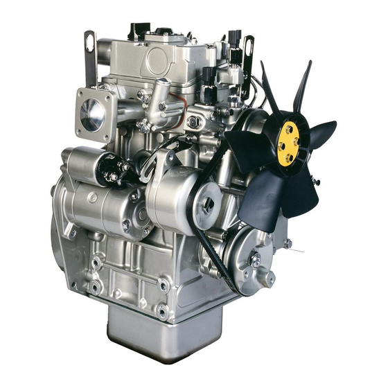
400 series engines. Due to individual applications, your engine may appear different from the illustrations. Note: Individual components are detailed on the 404D-22T turbocharged engine only. g01299985 Illustration 9 Typical view of the 402D-05 engine This document is printed from SPI². Not for RESALE... - Page 14 SEBU8311-02 Product Information Section Model Views g01300431 Illustration 10 Typical view of the 403D-15T engine This document is printed from SPI². Not for RESALE...
- Page 15 SEBU8311-02 Product Information Section Model Views g01304893 Illustration 11 Front and right side view of the 404D-22T Engine (1) Fuel shutoff solenoid (5) Throttle lever (9) Engine oil filter (2) Number one fuel injector (6) Cover plate for the accessory drive (10) Fuel injection pump (3) Water pump (7) Engine oil level gauge...
-
Page 16: Engine Description
SEBU8311-02 Product Information Section Model Views g01305224 Illustration 12 Front and left side view of the 404D-22T Engine (13) Top engine oil filler cap (19) Water temperature regulator housing (25) Fan drive belt (14) Crankcase breather (20) Starting motor solenoid (26) Crankshaft pulley (15) Rear Lifting eye (21) Electric starting motor... - Page 17 If any adjustments to the fuel injection pump timing and high idle are required you must refer to your Perkins distributoror your Perkins dealer. Some fuel injection pumps have mechanical governors that control the engine rpm. Some fuel injection pumps have a governor that is electrically controlled.
- Page 18 Illustration 13 Illustration 14 (A) Exhaust valves (A) Exhaust valves (B) Inlet valves (B) Inlet valves Table 1 Table 2 402D-05 Engine Specifications 403D-07 Engine Specifications Maximum Operating Maximum Operating 3600 rpm 3600 rpm Speed (rpm) Speed (rpm) Cylinders and...
- Page 19 SEBU8311-02 Product Information Section Model Views 403D-11 Engine 403D-15 Engine g00852304 g00852304 Illustration 15 Illustration 16 (A) Exhaust valves (A) Exhaust valves (B) Inlet valves (B) Inlet valves Table 3 Table 4 403D-11 Engine Specifications 403D-15 Engine Specifications Maximum Operating Maximum Operating 3600 rpm 3000 rpm...
- Page 20 SEBU8311-02 Product Information Section Model Views 403D-15T Engine 403D-17 Engine g00852304 g00852304 Illustration 17 Illustration 18 (A) Exhaust valves (A) Exhaust valves (B) Inlet valves (B) Inlet valves Table 5 Table 6 403D-15T Engine Specifications 403D-17 Engine Specifications Maximum Operating Maximum Operating 3000 rpm 2600 rpm...
- Page 21 SEBU8311-02 Product Information Section Model Views 404D-15 Engine 404D-22 Engine g00296424 g00296424 Illustration 19 Illustration 20 (A) Exhaust valves (A) Exhaust valves (B) Inlet valves (B) Inlet valves Table 7 Table 8 404D-15 Engine Specifications 404D-22 Engine Specifications Maximum Operating Maximum Operating 3000 rpm 3000 rpm...
- Page 22 SEBU8311-02 Product Information Section Model Views 404D-22T Engine 404D-22TA Engine g00296424 g00296424 Illustration 21 Illustration 22 (A) Exhaust valves (A) Exhaust valves (B) Inlet valves (B) Inlet valves Table 9 Table 10 404D-22T Engine Specifications 404D-22TA Engine Specifications Maximum Operating Maximum Operating 3000 rpm 2800 rpm...
-
Page 23: Product Identification Information
Engine Identification i02164876 Reference Numbers Perkins engines are identified by a serial number. This number is shown on a serial number plate that is mounted above the fuel injection pump on the right Information for the following items may be needed to hand side of the engine block. - Page 24 If another fuel label is used, the equipment manufacturer must send a drawing or a photo of the label to Perkins Shibaura Engines Limited through the Perkins Distributor. This will ensure compliance of the label.
-
Page 25: Operation Section
Engine Lifting fixtures obsolete. If alterations are made, ensure that correct lifting devices are provided. Consult your Perkins dealer or your Perkins distributor for information regarding fixtures for correct engine lifting. i02593735... -
Page 26: Cooling System
Note: Certain corrosion inhibitors could cause damage to some engine components. Contact the Service Department of Perkins for advice. If freezing temperatures are expected, check the cooling system for adequate protection against 8. Operate the engine for a short period in order to freezing. -
Page 27: Exhaust System
When the engine protection has been completed in accordance with these instructions, this ensures that no corrosion will occur. Perkins are not responsible for damage which may occur when an engine is in storage after a period in service. -
Page 28: Gauges And Indicators
Determine and correct the cause of any significant change in the readings. Consult your Perkins dealer or your Perkins distributor for assistance. Ammeter – This gauge indicates the amount of charge or discharge in the battery charging circuit. -
Page 29: Features And Controls
SEBU8311-02 Operation Section Features and Controls Features and Controls i02593769 Fuel Shutoff The fuel shutoff solenoid is located on the fuel injection pump. When the fuel shutoff solenoid is activated, the solenoid moves the fuel rack to the “OFF” position. g01305771 Illustration 28 (1) Fuel shutoff solenoid... -
Page 30: Engine Starting
SEBU8311-02 Operation Section Engine Starting Engine Starting • Do not start the engine or move any of the controls if there is a “DO NOT OPERATE” warning tag or similar warning tag attached to the start switch or to the controls. i02194223 Before Starting Engine •... - Page 31 SEBU8311-02 Operation Section Engine Starting Refer to the OEM manual for your type of controls. i02177935 Use the following procedure to start the engine. Starting with Jump Start Cables 1. Move the throttle lever to the low idle position before you start the engine. NOTICE Do not operate the glow plugs for more than 60 sec- onds at one time.
-
Page 32: After Starting Engine
SEBU8311-02 Operation Section Engine Starting 3. Connect one negative end of the jump start cable to the negative cable terminal of the electrical source. Connect the other negative end of the jump start cable to the engine block or to the chassis ground. -
Page 33: Engine Operation
Fuel Conservation Practices i02176671 Engine Operation The efficiency of the engine can affect the fuel economy. Perkins design and technology in manufacturing provides maximum fuel efficiency in all applications. Follow the recommended procedures Correct operation and maintenance are key factors... -
Page 34: Engine Stopping
SEBU8311-02 Operation Section Engine Stopping Engine Stopping i03756631 After Stopping Engine i02334873 Stopping the Engine Note: Before you check the engine oil, do not operate the engine for at least 10 minutes in order to allow the engine oil to return to the oil pan. NOTICE •... -
Page 35: Cold Weather Operation
“Starting with Jump Start Cables.” for instructions. Recommendations from your Perkins dealer or Viscosity of the Engine Lubrication your Perkins distributor are based on past proven practices. The information that is contained in this section provides guidelines for cold weather operation. -
Page 36: Idling The Engine
This fuel and oil causes soft carbon deposits to form on the valve stems. Note: Perkins discourages the use of all air flow Generally, the deposits do not cause problems and restriction devices such as radiator shutters. - Page 37 Fuel and the Effect from Cold Weather Note: Group 3 fuels reduce the life of the engine. The use of Group 3 fuels is not covered by the Perkins warranty. Group 3 fuels include Low Temperature Fuels and Note: Only use grades of fuel that are recommended Aviation Kerosene Fuels.
-
Page 38: Fuel Related Components In Cold Weather
SEBU8311-02 Operation Section Cold Weather Operation i01903588 Fuel Related Components in Cold Weather Fuel Tanks Condensation can form in partially filled fuel tanks. Top off the fuel tanks after you operate the engine. Fuel tanks should contain some provision for draining water and sediment from the bottom of the tanks. -
Page 39: Maintenance Section
filter. Refer to the Operation and Maintenance Manual, 403D-11 Engine “Maintenance Section” for more information on Lubricant Specifications. Table 13 403D-11 Engine 402D-05 Engine Refill Capacities Table 11 Compartment or System Minimum Maximum 402D-05 Engine 4.4 L... - Page 40 Total Cooling System. Engines with auxiliary oil filters will require additional oil. Refer to the OEM specifications for the capacity of the auxiliary oil 402D-05 Engine filter. The Total Lubrication System includes the capacity for the...
- Page 41 Total Cooling System in this row. The “Engine Manufacturers Association Recommended Guideline on Diesel Engine Oil” is recognized by Perkins. For detailed information about this guideline, see the latest edition of EMA publication, “EMA DHD -1”. This document is printed from SPI². Not for RESALE...
-
Page 42: Engine Oil
The classifications CD-2 and American Petroleum Institute CH-4 classification. Therefore, these oils will also CF-2 are for two-cycle diesel engines. Perkins does not sell meet the requirements for diesel engines that require engines that utilize CD-2 and API CF-2 oils. - Page 43 API CH-4 oils may be by “ASTM D2896”. The minimum TBN of the oil used in Perkins engines that use API CG-4 and API is 5 regardless of fuel sulfur level. Illustration 30 CF-4 oils. API CH-4 oils will generally exceed the demonstrates the TBN.
- Page 44 Re-refined Base Stock Oils Greater than 1.0 0.50 of normal Re-refined base stock oils are acceptable for use in Perkins engines if these oils meet the Lubricant Viscosity Recommendations performance requirements that are specified by Perkins. Re-refined base stock oils can be used The correct SAE viscosity grade of oil is determined exclusively in finished oil or in a combination with...
-
Page 45: Aftermarket Oil Additives
Aftermarket Oil Additives • Tests are conducted in order to detect Perkins does not recommend the use of aftermarket contamination of the oil by water, glycol or fuel. additives in oil. It is not necessary to use aftermarket additives in order to achieve the engine's maximum •... - Page 46 Table 27 Acceptable Water • Cavitation of the water pump Property Maximum Limit For optimum performance, Perkins recommends a Chloride (Cl) 40 mg/L 1:1 mixture of a water/glycol solution. Sulfate (SO 100 mg/L Note: Use a mixture that will provide protection...
-
Page 47: Coolant Recommendations
_________ _________________________________ Society for Testing and Materials • Automotive applications The following two coolants are used in Perkins diesel The anti-corrosion package for ELC is different from engines: the anti-corrosion package for other coolants. ELC is an ethylene glycol base coolant. However, ELC Preferred –... -
Page 48: Elc Cooling System Maintenance
This will lower the ability of the coolant to 4. Use Perkins cleaner to clean the system. Follow protect the system from pitting, from cavitation, from the instruction on the label. - Page 49 Dispose of the coolant according to local Use the equation that is in Table 32 to determine the regulations. Flush the system with clean water. Fill amount of Perkins SCA that is required when the the system with the Perkins ELC. cooling system is initially filled.
-
Page 50: General Information
filled with NOTICE new coolant. The footnotes are a key part of the Perkins Specifica- tion for Distillate Diesel Fuel Table. Read ALL of the • Clean the cooling system whenever the coolant is footnotes. - Page 51 SEBU8311-02 Maintenance Section Refill Capacities Table 36 Perkins Specification for Distillate Diesel Fuel Property UNITS Requirements “ASTM”Test “ISO”Test Aromatics %Volume 35% maximum D1319 “ISO”3837 D482 %Weight 0.02% maximum “ISO”6245 Carbon Residue on %Weight 0.35% maximum D524 “ISO”4262 10% Bottoms Cetane Number...
-
Page 52: Diesel Fuel Characteristics
Regional regulations, national regulations or international regulations can require a fuel with a specific sulfur limit. Consult all applicable regulations before selecting a fuel for a given engine application. Perkins fuel systems and engine components can operate on high sulfur fuels in territories that are non-emissions regulated. - Page 53 (59 °F). for less than than 37 kW or equal to Perkins recommends a value of density of 841 kg/m 37 kW in order to obtain the correct power output. Lighter Models 402D-05, 404D-22, fuels are acceptable but these fuels will not produce...
- Page 54 SEBU8311-02 Maintenance Section Refill Capacities Lubricity Table 39 Fuel Groups Classification This is the capability of the fuel to prevent pump wear. The fluid's lubricity describes the ability of the Group 1 Preferred fuels Full life of the Product fluid to reduce the friction between surfaces that are under load.
- Page 55 Environmental • “Jet A (ASTM D1655)” Protection Agency (EPA) and European Certification fuels. Perkins does not certify engines on any other • “Jet A1 (ASTM D1655)” fuel. The user of the engine has the responsibility...
- Page 56 SEBU8311-02 Maintenance Section Refill Capacities • • The oil change interval can be affected by the use Biodiesel is an excellent medium for microbial of biodiesel. Use Services Oil Analysis in order contamination and growth. Microbial contamination to monitor the condition of the engine oil. Use and growth can cause corrosion in the fuel system Services Oil Analysis also in order to determine the and premature plugging of the fuel filter.
- Page 57 Your fuel supplier or the fuel manufacturer will add the appropriate supplemental diesel fuel additives. Perkins recognizes the fact that additives may be required in some special circumstances. Fuel additives need to be used with caution. The additive may not be compatible with the fuel.
-
Page 58: Maintenance Recommendations
Remove the cooling system pressure cap onto a chassis frame or rail. Consult the OEM of the slowly in order to relieve pressure. equipment or your Perkins dealer regarding welding on a chassis frame or rail. Fuel System... - Page 59 SEBU8311-02 Maintenance Section Maintenance Recommendations 1. Stop the engine. Turn the switched power to the OFF position. 2. Disconnect the negative battery cable from the battery. If a battery disconnect switch is provided, open the switch. 3. Disconnect the J1/P1 and J2/P2 connectors from the ECM.
-
Page 60: Maintenance Interval Schedule
SEBU8311-02 Maintenance Section Maintenance Interval Schedule Alternator - Inspect ..........62 i03653629 Engine Crankcase Breather - Replace ....75 Maintenance Interval Schedule Engine Mounts - Inspect ........75 Starting Motor - Inspect ........89 Every 3000 Service Hours When Required Cooling System Water Temperature Regulator - Battery - Replace .......... - Page 61 SEBU8311-02 Maintenance Section Aftercooler Core - Clean/Test 10. Install the core. Refer to the OEM information for i03632383 the correct procedure. Aftercooler Core - Clean/Test (Air-To-Air Aftercooler) 11. After cleaning, start the engine and accelerate the engine to high idle rpm. This will help in the removal of debris and drying of the core.
- Page 62 Maintenance Section Alternator - Inspect i02322311 Alternator - Inspect Perkins recommends a scheduled inspection of the alternator. Inspect the alternator for loose connections and correct battery charging. Check the ammeter (if equipped) during engine operation in order to ensure correct battery performance and/or correct performance of the electrical system.
- Page 63 SEBU8311-02 Maintenance Section Alternator and Fan Belts - Replace 2. Move the alternator in order to increase or i02322315 decrease the belt tension. Battery - Replace 3. Tighten adjusting bolt (1). Tighten mounting bolts (2). Refer to the Specifications Manual for the correct torque settings.
- Page 64 SEBU8311-02 Maintenance Section Battery Electrolyte Level - Check 8. Connect the NEGATIVE “-” cable to the NEGATIVE i02323088 “-” battery terminal. Battery or Battery Cable - Disconnect i02747977 Battery Electrolyte Level - Check The battery cables or the batteries should not be removed with the battery cover in place.
- Page 65 The full distillation • The fuel has entered the cooling system and the procedure is the only method acceptable by Perkins to coolant is contaminated. reclaim the coolant. Note: When the cooling system is cleaned, only For information regarding the disposal and the clean water is needed.
- Page 66 SEBU8311-02 Maintenance Section Cooling System Coolant (ELC) - Change 6. Start the engine. Inspect the cooling system for 3. Fill the cooling system with clean water. Install the cooling system filler cap. leaks and for correct operating temperature. 4. Start and run the engine at low idle until the i02595733 temperature reaches 49 to 66 °C (120 to 150 °F).
- Page 67 filler cap. for reuse in engine cooling systems. The full distillation procedure is the only method acceptable by Perkins to 3. Start and run the engine at low idle. Increase the reclaim the coolant.
- Page 68 Note: The cooling system may not have been up during normal engine operation. The additional provided by Perkins. The procedure that follows volume will be forced into the coolant recovery tank is for typical cooling systems. Refer to the OEM during engine operation.
-
Page 69: Test For Sca Concentration
SEBU8311-02 Maintenance Section Cooling System Supplemental Coolant Additive (SCA) - Test/Add Add the SCA, If Necessary Pressurized System: Hot coolant can cause seri- NOTICE ous burns. To open the cooling system filler cap, Do not exceed the recommended amount of sup- stop the engine and wait until the cooling system plemental coolant additive concentration. - Page 70 filler cap and install a new filler cap. If the gasket Install” for the replacement procedure of the water is not damaged, use a suitable pressurizing pump temperature regulator, or consult your Perkins dealer in order to pressure test the filler cap. The correct or your Perkins distributor.
-
Page 71: Servicing The Air Cleaner Elements
If the air cleaner element becomes plugged, the air can split the material of the air cleaner element. Unfiltered air will drastically accelerate internal g00736431 engine wear. Your Perkins dealer has the proper air Illustration 39 cleaner elements for your application. Consult your (1) Cover Perkins dealer for the correct air cleaner element. - Page 72 NOTICE Perkins recommends certified air filter cleaning ser- Pressurized air can be used to clean primary air vices that are available at Perkins dealers. The cleaner elements that have not been cleaned more Perkins cleaning process uses proven procedures to than two times.
- Page 73 SEBU8311-02 Maintenance Section Engine Air Cleaner Element (Single Element) - Inspect/Replace Vacuum Cleaning Vacuum cleaning is a good method for cleaning primary air cleaner elements which require daily cleaning because of a dry, dusty environment. Cleaning with pressurized air is recommended prior to vacuum cleaning.
-
Page 74: Test The Service Indicator
SEBU8311-02 Maintenance Section Engine Air Cleaner Service Indicator - Inspect • A wide variety of air cleaners may be installed for use Check the movement of the yellow core when with this engine. Consult the OEM information for the the engine is accelerated to the engine rated correct procedure to replace the air cleaner. - Page 75 Engine Mounts - Inspect Note: The engine mounts may not have been supplied by Perkins. Refer to the OEM information for further information on the engine mounts and the correct bolt torque. Inspect the engine mounts for deterioration and for correct bolt torque.
-
Page 76: Drain The Engine Oil
Engine Oil and Filter - Change NOTICE Perkins oil filters are built to Perkins specifications. Use of an oil filter not recommended by Perkins could result in severe engine damage to the engine bear- ings, crankshaft, etc., as a result of the larger waste particles from unfiltered oil entering the engine lubri-... -
Page 77: Fill The Engine Crankcase
Maintenance Manual for more information on refill uncommon to find small amounts of debris in capacities. the oil filter. Consult your Perkins dealer or your Perkins distributor in order to arrange for a further NOTICE analysis if an excessive amount of debris is found If equipped with an auxiliary oil filter system or a re-... - Page 78 Refer to the Service Manual or your au- clean the area around a fuel system component that thorized Perkins dealer or your Perkins distributor for will be disconnected. Fit a suitable cover over discon- the complete valve lash adjustment procedure.
- Page 79 Ensure that the air is removed from the primary filter Consult your authorized Perkins dealer or your before you prime the fuel filters. Refer to illustration Perkins distributor for further assistance.
- Page 80 SEBU8311-02 Maintenance Section Fuel System - Prime g01327360 g01327363 Illustration 50 Illustration 52 Element Spin-on filter with fuel priming pump (2) Fuel valve (5) Vent screw (3) Vent screw Vent screw (3) is installed on the filter that has an element.
- Page 81 SEBU8311-02 Maintenance Section Fuel System - Prime g01301853 Illustration 53 (6) Hand priming pump (8) Electrical priming pump (7) In-line priming pump (9) Fuel transfer pump g01304597 Illustration 54 (10) Connector bolt (11) Fuel return line (12) Connector bolt Hand Priming Pump 6 1.
- Page 82 SEBU8311-02 Maintenance Section Fuel System - Prime 3. Operate hand priming pump (6). When fuel free 1. Ensure that fuel valve (2) for the fuel filter that from air flows from the vent screw tighten the vent has an element is in the ON position. Refer to screw.
-
Page 83: Fuel Filter With Canister
SEBU8311-02 Maintenance Section Fuel System Filter - Replace Note: Do not operate the starting motor for more than 15 seconds. If the engine does not start after 15 seconds, stop and wait for 30 seconds before trying again. i02608681 Fuel System Filter - Replace Fuel leaked or spilled onto hot surfaces or elec- trical components can cause a fire. -
Page 84: Fuel Filter With Element
SEBU8311-02 Maintenance Section Fuel System Filter - Replace The fuel system will need to be primed after the new filter is installed. Refer to this Operation and Maintenance Manual, “Fuel System - Prime”. Fuel Filter with Element 1. Close the fuel supply valve (1). g01334893 Illustration 57 Typical example... - Page 85 SEBU8311-02 Maintenance Section Fuel System Primary Filter/Water Separator - Drain NOTICE The water separator is not a filter. The water separa- tor separates water from the fuel. The engine should never be allowed to run with the water separator more than half full.
-
Page 86: Fuel Storage Tanks
SEBU8311-02 Maintenance Section Fuel Tank Water and Sediment - Drain Some fuel tanks use supply pipes that allow water i02335436 and sediment to settle below the end of the fuel Fuel Tank Water and Sediment supply pipe. Some fuel tanks use supply lines that - Drain take fuel directly from the bottom of the tank. -
Page 87: Replace The Hoses And The Clamps
Loosen the cooling system pressure cap slowly in order to relieve the pres- The radiator is not usually supplied by Perkins. The sure. following text describes a typical cleaning procedure for the radiator. -
Page 88: Severe Service Application
Refer to the standards for the engine or consult your with detergent and hot water. Thoroughly rinse the Perkins dealer or your Perkins distributor in order to core with clean water. determine if the engine is operating within the defined parameters. -
Page 89: Environmental Factors
Valve Test” for more information on the checking procedure components can be damaged by carbon buildup if and for specifications or consult your Perkins dealer the engine is frequently started and stopped in very or your Perkins distributor for assistance. - Page 90 Disassembly and Assembly 4. Fasten the air intake pipe and the exhaust outlet Manual, “Water Pump - Remove and Install” for more pipe to the turbocharger housing. information or consult your Perkins dealer or your Perkins distributor. i02177973 •...
- Page 91 SEBU8311-02 Maintenance Section Water Pump - Inspect Belts for multiple groove pulleys must be replaced as matched sets. If only one belt is replaced, the belt will carry more load than the belts that are not replaced. The older belts are stretched. The additional load on the new belt could cause the belt to break.
-
Page 92: Warranty Section
Emissions Warranty. Consult your authorized Perkins dealer or your authorized Perkins distributor in order to determine if your engine is emissions certified and if your engine is subject to an Emissions Warranty. - Page 93 SEBU8311-02 Index Section Index Electrical System ........... 12 After Starting Engine ..........32 Grounding Practices .......... 12 After Stopping Engine..........34 Aftercooler Core - Clean/Test (Air-To-Air Emergency Stopping ..........34 Aftercooler) ............61 Emissions Certification Film ........24 Aftercooler Core - Inspect........61 Emissions Warranty Information......
- Page 94 SEBU8311-02 Index Section Maintenance Recommendations ......58 Foreword ..............4 California Proposition 65 Warning ....... 4 Maintenance Section ..........39 Literature Information........... 4 Model View Illustrations......... 13 Maintenance ............4 Model Views ............13 Maintenance Intervals.......... 4 Operation ............. 4 Overhaul ..............
- Page 95 SEBU8311-02 Index Section Warranty Section ........... 92 Water Pump - Inspect..........91 Welding on Engines with Electronic Controls ..58 This document is printed from SPI². Not for RESALE...
- Page 96 SEBU8311-02 Index Section This document is printed from SPI². Not for RESALE...
- Page 97 Product and Dealer Information Note: For product identification plate locations, see the section “Product Identification Information” in the Operation and Maintenance Manual. Delivery Date: Product Information Model: Product Identification Number: Engine Serial Number: Transmission Serial Number: Generator Serial Number: Attachment Serial Numbers: Attachment Information: Customer Equipment Number: Dealer Equipment Number:...
- Page 98 ©2010 Perkins Engines Company Limited Printed in U.K. All Rights Reserved This document is printed from SPI². Not for RESALE...