Table of Contents
Advertisement
Quick Links
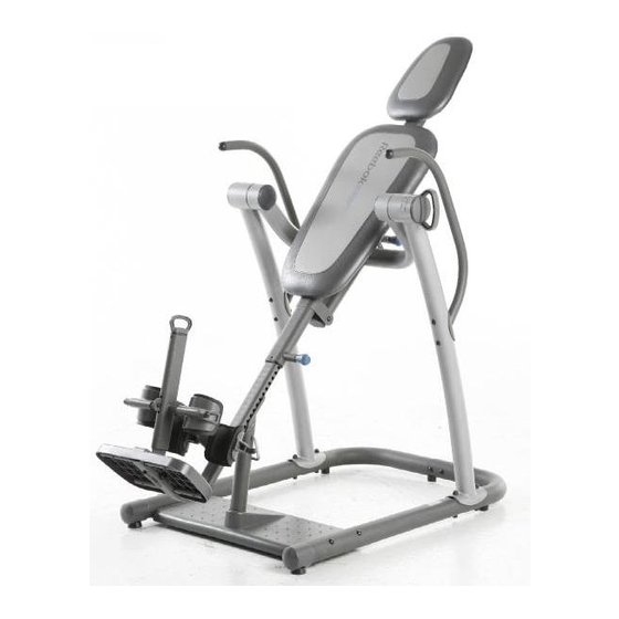
Model No. RBBE1996.5
Serial No.
Write the serial number in the
space above for future reference.
Serial Number Decal (Under Seat)
QUESTIONS?
As a manufacturer, we are com-
mitted to providing complete cus-
tomer satisfaction. If you have
questions, or if parts are missing,
PLEASE DO NOT CONTACT
THE STORE; please contact
Customer Care.
IMPORTANT: You must note the
product model number and
serial number (see the drawing
above) before contacting us:
CALL TOLL-FREE:
1-877-994-4999
Mon.–Fri. 6 a.m.–6 p.m. MST
Sat. 8 a.m.–4 p.m. MST
ON THE WEB:
www.reebokservice.com
CAUTION
Read all precautions and instruc-
tions in this manual before using
this equipment. Save this manual
for future reference.
USER'S MANUAL
Visit our website at
www.reebokhomefitness.com
new products, prizes,
fitness tips, and much more!
Advertisement
Table of Contents

Related Manuals for Reebok RBBE1996.5


Summary of Contents for Reebok RBBE1996.5
- Page 1 Model No. RBBE1996.5 Serial No. Write the serial number in the space above for future reference. Serial Number Decal (Under Seat) QUESTIONS? As a manufacturer, we are com- mitted to providing complete cus- tomer satisfaction. If you have questions, or if parts are missing, PLEASE DO NOT CONTACT THE STORE;...
-
Page 2: Table Of Contents
TABLE OF CONTENTS WARNING DECAL PLACEMENT ............. .2 IMPORTANT PRECAUTIONS . -
Page 3: Important Precautions
IMPORTANT PRECAUTIONS WARNING: To reduce the risk of serious injury, read all important precautions and instructions in this manual and all warnings on the inversion table before using the inversion table. ICON assumes no responsibility for personal injury or property damage sustained by or through the use of the inversion table. -
Page 4: Before You Begin
BEFORE YOU BEGIN Thank you for selecting the versatile REEBOK INVERSION SYSTEM inversion table. The inversion table will increase your intervertebral dimension, decrease pressure on intervertebral discs, stretch and relax your muscles, and temporarily relieve back pain associated with the listed conditions. For your benefit, read this manual carefully before using the inversion table. -
Page 5: Part Identification Chart
PART IDENTIFICATION CHART See the drawings below to identify small parts used in assembly. The number in parentheses by each drawing is the key number of the part, from the PART LIST near the end of this manual. Note: Some small parts may have been pre-assembled. -
Page 6: Assembly
ASSEMBLY Make Assembly Easier This manual is designed to ensure that the inversion table can be assembled successfully by almost anyone. However, the inversion table has many parts, and the assembly process will take time. Most people find that if they set aside plenty of time, assembly goes smoothly. - Page 7 2. Attach the Left Base (1) to the Right Base (2) with two M10 x 80mm Button Bolts (52), four M10 Curved Washers (50), and two M10 Nylon Locknuts (65). Attach another Foot (42) to the Right Base (2) with an M4 x 20mm Screw (71). 3.
- Page 8 5. Attach the Center Base (3) to the Left and Right Bases (1, 2) with four M10 x 80mm Button Bolts (52), four M10 Curved Washers (50), and four M10 Nylon Locknuts (65). 6. See the inset drawing. Identify the Center Frame (7).
- Page 9 8. Attach the Top Cover (23) and the Bottom Cover (24) to the Center Frame (7) with two M4 x 15mm Screws (58) and an M4 x 30mm Screw (63). Attach the Center Frame Extension (6) to the Center Frame (7) with two M10 x 53mm Button Bolts (49) and two M10 Nylon Locknuts (65).
- Page 10 11. See the left inset drawing. Identify the Top Tube (16), the Bottom Tube (17), and the Ankle Brace Tube (18); the Tubes have differ- ent lengths and holes in different positions. Orient the Top Tube (16) and the Bottom Tube (17) so that the largest holes are on top (see the right inset drawing), and insert them into the indicated holes in the Leg...
- Page 11 14. Identify the two Rear Ankle Braces (34), which have holes in the indicated locations. Slide a Rear Ankle Brace (34) onto the Ankle Brace Tube (18). Attach the Rear Ankle Brace with two M4 x 15mm Screws (58). Make sure that the Screws are tightened into the indi- cated holes in the Ankle Brace Tube.
- Page 12 17. Attach the Headrest (20) to the Headrest Frame (9) with two M6 x 18mm Button Screws (55), an M6 x 55mm Button Screw (56), and three M6 Washers (62). Attach the Backrest (21) to the Backrest Frame (8) in the same way. 18.
-
Page 13: Adjustment
ADJUSTMENT This section explains how to adjust the inversion table. See DEVELOPING A PROGRAM on page 16 for impor- tant information about how to get the most benefit from the inversion table. Make sure that all parts are properly tightened each time you use the inversion table. Replace any worn parts immediately. - Page 14 USING THE ANKLE LOCK To secure your ankles in the inversion table, pull the Ankle Lock Assembly (33) out as far as it will go, and move the Lock Frame (11) away from the Leg Frame (10). Stand on the Foot Plate (19), with the backs of your legs against the Rear Ankle Braces (34).
-
Page 15: Rotating On The Inversion Table
ROTATING ON THE INVERSION TABLE This section explains how to rotate back on the inversion table, and then return to the starting position. Before using the inversion table, see the ADJUSTMENT section starting on page 13 to correctly set up the inversion table. -
Page 16: Developing A Program
DEVELOPING A PROGRAM This section contains information and suggestions about using the inversion table. Make sure that all parts are properly tightened each time you use the inversion table. Replace any worn parts immediately. See the ADJUST- MENT section starting on page 13 to identify parts referred to in this section. BENEFITING FROM USING THE INVERSION TABLE If you feel nauseated while using the inversion table, return to the starting position. - Page 17 NOTES...
-
Page 18: Part List
PART LIST—Model No. RBBE1996.5 Key No. Qty. Description Left Base Right Base Center Base Left Frame Right Frame Center Frame Extension Center Frame Backrest Frame Headrest Frame Leg Frame Lock Frame Handle Support Leg Base Support Bracket Top Tube Bottom Tube... -
Page 19: Exploded Drawing
EXPLODED DRAWING—Model No. RBBE1996.5 R0907A... -
Page 20: Ordering Replacement Parts
ORDERING REPLACEMENT PARTS To order replacement parts, please see the front cover of this manual. To help us assist you, be prepared to pro- vide the following information when contacting us: • the model number and serial number of the product (see the front cover of the manual) •...