Table of Contents
Advertisement
Advertisement
Table of Contents

Related Manuals for LAUMAS TLM8


Summary of Contents for LAUMAS TLM8
- Page 1 Microlectra bv. Hermanus Boerhaavestraat 6. 3261 ME Oud-Beijerland. Netherlands. Tel 31(0)186-616290 Fax 31(0)186-610349 www.microlectra.nl info@microlectra.nl Installation and User Manual version 1.01 TLM8 2004/108/EC EN55022 EN61000-6-2 EN61000-6-4 SYSTEM IDENTIFICATION...
- Page 2 No guarantee against misuse. Batteries: Laumas provides 1 year guarantee from the date of delivery note, against material defects or battery manufacturing faults. Disposal of Waste Equipment by Users in Private Households in the European Union This symbol on the product or on its packaging indicates that this product must not be disposed of with your other household waste.
-
Page 3: Table Of Contents
TABLE OF CONTENTS USER WARNINGS ........................1 RECOMMENDATIONS FOR CORRECT INSTALLATION OF WEIGHING INSTRUMENTS . 1 RECOMMENDATIONS FOR CORRECT INSTALLATION OF THE LOAD CELLS ....1 LOAD CELL INPUT TEST (QUICK ACCESS) ................3 LOAD CELL TESTING ....................... 3 MAIN SPECIFICATIONS OF THE INSTRUMENT ..............4 TECHNICAL SPECIFICATIONS .................... - Page 4 TEST ............................29 EVENTS LOG ........................... 29 INFO MENU ..........................30 SETPOINT PROGRAMMING ....................30 ALARMS ..........................31 PRINTING EXAMPLES ......................33 RESERVED FOR THE INSTALLER ..................35 MENU LOCKING ........................35 MENU UNLOCKING ......................... 35 TEMPORARY MENU UNLOCKING ..................35 DATA DELETION AND PROGRAM SELECTION ..............
-
Page 5: User Warnings
USER WARNINGS RECOMMENDATIONS FOR THE PROPER USE OF WEIGHING INSTRUMENT Keep away from heat sources and direct sunlight Repair the instrument from rain (except special IP versions) Do not wash with water jets (except special IP versions) Do not dip in water Do not spill liquid on the instrument Do not use solvents to clean the instrument Do not install in areas subject to explosion hazard (except special Atex versions) - Page 6 WELDING: Avoid welding with the load cells already installed. If this cannot be avoided, place the welder ground clamp close to the required welding point to prevent sending current through the load cell body. WINDY CONDITIONS - KNOCKS - VIBRATIONS: The use of weigh modules is strongly recommended for all load cells to compensate for misalignment of the support surfaces.
-
Page 7: Load Cell Input Test (Quick Access)
LOAD CELL INPUT TEST (QUICK ACCESS) From the weight display, press for 3 seconds: the top of the display shows the gross weight;... -
Page 8: Main Specifications Of The Instrument
RS485 serial port for connection to: PC/PLC up to 32 instruments (max 99 with line repeaters) by ASCII Laumas or ModBus R.T.U. protocol, remote display, printer. Optional: integrated Profibus DP, DeviceNet, CANopen, Profinet IO, Ethernet/IP, Ethernet TCP/IP, Modbus TCP, RS232/RS485, SERCOS III, PowerLink, CC-Link output. -
Page 9: Technical Specifications
TECHNICAL SPECIFICATIONS POWER SUPPLY and CONSUMPTION (VDC) 12/24 VDC ±10%; 5 W NO. OF LOAD CELLS IN PARALLEL and SUPPLY max 16 (350 ohm); 5 VDC / 240 mA LINEARITY / ANALOG OUTPUT LINEARITY < 0.01% F.S.; < 0.01% F.S. THERMAL DRIFT / ANALOG OUTPUT THERMAL DRIFT <... -
Page 10: Electrical Connections
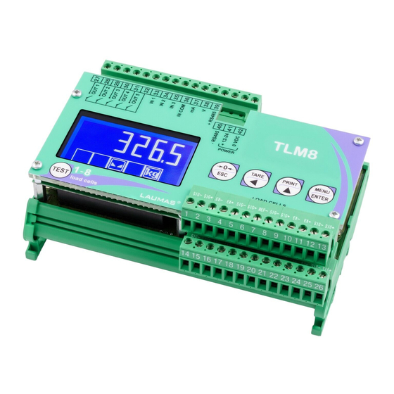
ELECTRICAL CONNECTIONS BASIC INFORMATION - It is recommended that the power supply negative pole be grounded. - It is possible to supply up to 16 350 ohm load cells. - Connect terminal SUPPLY to the RS485 common of the connected instruments in the event that these receive alternating current input or that they have an optically isolated RS485. - Page 11 OUTPUTS INPUTS ANALOG RS485 12/24 VDC max 115 VAC 150 mA supply 5÷24 VDC OUTPUT SUPPLY TERMINALS LEGEND -LOAD CELL 1 SIGNAL 22 +LOAD CELL 7 SIGNAL -LOAD CELLS 7 and 8 EXCITATION (-EX) +LOAD CELL 1 SIGNAL LOAD CELLS SHIELD -LOAD CELLS 1 and 2 EXCITATION (-EX) 24 +LOAD CELLS 7 and 8 EXCITATION (+EX) LOAD CELLS SHIELD...
-
Page 12: Keys And Symbols Functions
KEYS AND SYMBOLS FUNCTIONS Long press Short press Into menus (3 s) Cancel or return to previous Semi-automatic zero Tare resetting menu Select figure to be modified Gross Net Net Gross or go to previous menu item. Modify selected figure or go Weight print mV load cell test to next menu item... -
Page 13: Menu Map
MENU MAP Into menus changes are applied right after pressing the ENTER key (no further confirmation is required). SETPOINT ... - Page 14 ...
-
Page 15: Instrument Commissioning
INSTRUMENT COMMISSIONING Upon switch-on, the display shows in sequence: - (ONLY in case of approved program); - instrument model (e.g.: ... -
Page 16: Programming Of System Parameters
PROGRAMMING OF SYSTEM PARAMETERS From the weight display, press simultaneously keys MENU and ESC to access the parameter setting. MENU/ENTER: to enter a menu/confirm the data entry. : to modify the displayed figure or menu item. : to select a new figure or modify the displayed menu item. ESC: to cancel and return to the previous menu. -
Page 17: Maximum Capacity
MAXIMUM CAPACITY ... -
Page 18: Real Calibration (With Sample Weights)
REAL CALIBRATION (WITH SAMPLE WEIGHTS) After having performed the THEORETICAL CALIBRATION, EQUALIZATION and TARE WEIGHT ZERO SETTING, this function allows correct calibration to be done using sample weights of known value and, if necessary, any deviations of the indicated value from the correct value to... -
Page 19: Confirmation And Change Of Active Channels
CONFIRMATION AND CHANGE OF ACTIVE CHANNELS After performing the calibration and verifying that the system works properly, you can confirm the channels automatically detected by the instrument; in this way, in case of accidental interruption of the cable of one or more load cells, the instrument displays the alarm. Automatic load cells detection is enabled by default on all 8 channels of the instrument. -
Page 20: Equalization
EQUALIZATION At the end of the equalization you must perform the TARE WEIGHT ZERO SETTING and, if necessary,the REAL CALIBRATION. REAL EQUALIZATION ... -
Page 21: Filter On The Weight
FILTER ON THE WEIGHT Setting this parameter allows a stable weight display to be obtained. To increase the effect (weight more stable) increase the value (from 0 to 9, default 4). -
Page 22: Zero Parameters
ZERO PARAMETERS RESETTABLE WEIGHT SETTING FOR SMALL WEIGHT CHANGES ... -
Page 23: Setting Units Of Measure
SETTING UNITS OF MEASURE These are the available units of measure: ... - Page 24 If the unit of measure chosen is: : pounds, the value set in will be multiplied by the weight value currently displayed; : newton, the value set in will be multiplied by the weight value currently displayed; ...
-
Page 25: Outputs And Inputs Configuration
OUTPUTS AND INPUTS CONFIGURATION ... -
Page 26: Semi-Automatic Tare (Net/Gross)
INPUTS Default: input 1 = input 2 = input 3 = Possible operation modes: - ... -
Page 27: Preset Tare (Subtractive Tare Device)
PRESET TARE (SUBTRACTIVE TARE DEVICE) It is possible to manually set a preset tare value to be subtracted from the display value provided that the ... -
Page 28: Peak
PEAK By keeping the PEAK input closed the maximum weight value reached remains displayed. By opening the input the current weight is displayed. If you wish to use this input to view a sudden variation peak, set the FILTER ON THE WEIGHT to 0. -
Page 29: Serial Communication Setting
Minimum and maximum values which can be set for zero and full scale corrections: ANALOG OUTPUT TYPE Minimum Maximum 0÷10 V -0.150 10.200 0÷5 V -0.150 5.500 0÷20 mA -0.200 22.000 4÷20 mA -0.200 22.000 NOTE: the analog output may also be used in the opposite manner, i.e. the weight setting that corresponds to the analog zero (... - Page 30 - if the instrument shows the net weight, the remote display shows the net weight alternated with the message . - : printer. - ...
-
Page 31: Rs485 Serial Communication
RS485 SERIAL COMMUNICATION TLM8 TLM8 TLM8 max 500 m 24 VDC RS485 + RS485 + RS485 - RS485 - CONVLAU If the RS485 network exceeds 100 metres in length or baud-rate over 9600 are used, two terminating resistors are needed at the ends of the network. Two... -
Page 32: Automatic Diagnostics Of Load Distribution
AUTOMATIC DIAGNOSTICS OF LOAD DISTRIBUTION Only use this function in systems where load distribution can be repeated with each change of weight (for example: liquid weighing). -
Page 33: Test
TEST - Load distribution: : it displays the active channels status (weight, load percentage on each channel, enabled channels and/or channels in error). -
Page 34: Info Menu
: it prints all events. INFO MENU ... -
Page 35: Alarms
ALARMS : no load cell detected, check the connections. : the load cell signal exceeds 39 mV; the conversion electronics (AD converter) is malfunctioning. - Page 36 Serial protocol alarms: MODE The response to the Bit LSB...
-
Page 37: Printing Examples
PRINTING EXAMPLES If the printer has been set (see section SERIAL COMMUNICATION SETTINGS), from the weight display press the PRINT key: BASIC PRINTOUT ----------------------- TLM8 BASE Addr:01 GROSS 878 kg 589 kg TARE 289 kg BASIC PRINTOUT (PEAK ENABLED): -----------------------... - Page 38 Current and stored distribution: from the and menus, keep pressed the PRINT key for more than 3 seconds while the weight is displayed. CURRENT DISTRIBUTION ----------------------- TLM8 BASE Addr:01 CURRENT...
-
Page 39: Reserved For The Installer
RESERVED FOR THE INSTALLER MENU LOCKING Through this procedure, it s possible to block the access to any menu on the instrument. Select the menu that you wish to lock: ... -
Page 40: Keypad Or Display Locking
PROGRAM SELECTION: confirm and use the arrow keys to select the desired program: : basic program, setpoint management only. : to be used when the loaded weighing system correspond to not loaded cells and vice versa (product increases while weight on load cells actually decreases). -
Page 41: Declaration Of Conformity
Niniejszym oświadczamy, że produkt, którego niniejsze oświadczenie dotyczy, jest zgodny z Deklaracja zgodności poniższymi normami. Заявление о Мы заявляем, что продукт, к которому относится данная декларация, соответствует соответствии перечисленным ниже нормам. Models: TLM8 Mark Applied EU Directive Standards Not Applicable (N/A) for VDC type 2006/95/EC Low Voltage Directive...