Table of Contents
Advertisement
Available languages
Available languages
Operator's Manual
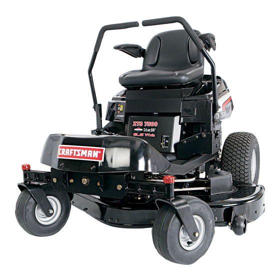
ZTS 7500
Zero-Turn Rear Engine Rider with Electric Start
Model No.
107.28791 (26 HP Kohler Engine with 50" Mower)
CAUTION: Before using this product, read
the manual and follow all its Safety Rules
and Operating Instructions.
Sears, Roebuck and Co., Hoffman Estates, IL 60179 U.S.A.
Visit our Craftsman website: www.sears.com/craftsman
For answers to your questions about this
product, call:
1-800-659-5917
Sears Craftsman Help Line
5 am - 5 pm, Mon - Sat
Nota: Una traducción en español de este Manual
del Operador puede encontrarse en la página 33.
TP 899-4871-01-CZ-C
7102360
Revision 01
Advertisement
Chapters
Table of Contents

Related Manuals for Craftsman 107.28791


Summary of Contents for Craftsman 107.28791
- Page 1 Operator’s Manual ZTS 7500 Zero-Turn Rear Engine Rider with Electric Start Model No. 107.28791 (26 HP Kohler Engine with 50” Mower) For answers to your questions about this CAUTION: Before using this product, read product, call: the manual and follow all its Safety Rules 1-800-659-5917 and Operating Instructions.
-
Page 2: Table Of Contents
For your convenience, IN HOME warranty service will still be available after the first 30 days of purchase, but a trip charge will apply. This charge will be waived if the Craftsman product is dropped off at an authorized Sears location. -
Page 3: Safety Rules & Information
SAFETY RULES Read these safety rules and follow them closely. Failure to obey these rules could result in loss of control of unit, severe personal injury or death to you, or bystanders, or damage to property or equipment. This mowing deck is capable of amputating hands and feet and throwing objects. The triangle in text signifies important cautions or warnings which must be followed. -
Page 4: Slope Operation
SLOPE OPERATION WARNING Slopes are a major factor related to loss-of-control and tip- Never operate on slopes greater than 17.6 percent over accidents, which can result in severe injury or death. (10°) which is a rise of 3-1/2 feet (106 cm) vertically in Operation on all slopes requires extra caution. - Page 6 SERVICE AND MAINTENANCE 13. If the fuel tank must be drained, it should be drained outdoors. Safe Handling of Gasoline 14. Replace faulty silencers/mufflers. 1. Extinguish all cigarettes, cigars, pipes, and other 15. Maintain or replace safety and instruction labels as sources of ignition.
- Page 7 SAFETY & OPERATION DECALS All DANGER, WARNING, CAUTION and instructional This unit has been designed and manufactured to messages on your rider and mower should be carefully provide you with the safety and reliability you would read and obeyed. Personal bodily injury can result when expect from an industry leader in outdoor power these instructions are not followed.
-
Page 8: Identification Numbers
Tilt the seat forward to access the ID tag. Model Description Name/Number For answers to your questions about this product, call: 1-800-659-5917 Stock Number Unit Serial Number Sears Craftsman Help Line, 5 am - 5 pm, Monday-Saturday. Date Purchased ENGINE REFERENCE DATA Engine Make Engine Model... -
Page 9: Pre-Operation
PRE-OPERATION Remove the Packaging Materials Fill-Up with FRESH Gasoline Remove the cardboard from the crate. Lift the seat deck to access the Remove any steel branding securing the fuel cap and tank. unit to the crate. Locate the manual Remove the fuel tank cap and fill packet. -
Page 10: Operation
OPERATION Right Left Ground Speed & Ground Speed Parking Brake Control Lever Lever Mower Cutting Height Switch Ground Speed Levers - Ground Speed Levers - Choke DRIVE Positons START/PARK Positons (Closed) Choke (Open) Fuel Tank Engine Speed (Fast) Engine CONTROL FUNCTIONS Speed (Slow) START... -
Page 11: Ignition Switch
Mower Cutting Height Switch Mower Blade Switch To increase the mower cutting height (raise the mower The yellow mower blade switch turns the mower blades deck), press the top of the yellow mower cutting height on and off. To turn the mower blades ON, pull the switch switch. -
Page 12: Checks Before Starting
CHECKS BEFORE STARTING • Check that the crankcase oil is filled to full mark on dipstick. • Fill the fuel tank with fresh fuel. FUEL RECOMMENDATIONS For daily operation: Use only unleaded gasoline with a pump sticker octane rating of 87 or higher. Gasohol (up to 10% ethyl alcohol, 90% unleaded gasoline by volume) is approved as a fuel. -
Page 13: Emergency Stopping
EMERGENCY STOPPING PUSHING THE RIDER BY HAND NOTE: Do not disengage the transmissions while parked In the event of an emergency the engine can be stopped by simply turning the ignition switch to STOP. Use this on a slope. method only in emergency situations. For normal engine 1. -
Page 14: Driving Practice
DRIVING PRACTICE - Smooth Travel The lever controls of the BASIC DRIVING zero turn rider are WARNING: Never operate on slopes greater than 17.6% highly responsive. (10°). See SLOPE OPERATION in the safety section. The BEST method of Zero turn riders operate differently from other four- handling the ground wheeled vehicles. -
Page 15: Advanced Driving
Practice Turning Around a Corner Practice Turning In Place While traveling forward allow one handle to gradually To “zero turn” means to turn in place. To turn in place, return back toward neutral. Practice several times before gradually move one ground speed control lever forward mowing. - Page 16 MOWER DECK REMOVAL & INSTALLATION NOTE: Perform mower removal and installation on a hard, level surface such as a concrete floor. WARNING After lowering the mower cutting height, engage parking brake, turn off the mower blades, turn the ignition switch to STOP, and remove key before attempting to install or remove the mower.
-
Page 17: Maintenance
MAINTENANCE MAINTENANCE SCHEDULE The following schedules should be followed for normal care of your rider and mower. RIDER MAINTENANCE, All Models Before Spring Yearly Each Use & Fall Hours Hours Hours Hours • Clean Debris from Rider and Engine Compartment * •... -
Page 18: Check Tire Pressure
Rider Maintenance Items WARNING Move the ground speed levers to START/PARK positions, turn the mower blades OFF, turn the ignition switch OFF, and wait for all moving parts to stop before accessing the engine compartment or performing any maintenance procedures. ACCESSING THE ENGINE COMPARTMENT Figure 12. - Page 19 LUBRICATION Service Interval: 25 hours. Lubricate the unit at the locations shown in Figures 15 through 19 as well as the following lubrication points. Grease: • front wheel grease fittings • front wheel bushings • mower pivots • mower arbors Use grease fittings when present.
- Page 20 CLEAN DECK & CHECK / REPLACE MOWER BLADES Service Interval: 25 hours or as required. WARNING For your personal safety, do not handle the sharp mower blades with bare hands. Careless or improper handling of blades may result in serious injury.
- Page 21 CLEANING THE BATTERY AND CABLES CHECK RIDER SAFETY Service Interval: 100 Hours SYSTEM WARNING Service Interval: Every 100 hours, every spring/fall, and after storage of 30 days or longer. Corrosion hazard. Batteries contain acid. Always keep the This unit is equipped with safety interlock switches. battery upright and do not spill the These safety systems are present for your safety.
- Page 22 CHECK / ADJUST PTO CLUTCH WARNING To avoid serious injury, perform adjustments only with engine stopped, key removed and tractor on level ground. Service Interval: 200 Hours. The Power Take Off (PTO) clutch drives the mower blades. The PTO clutch is engaged and disengaged by the mower blade switch.
-
Page 23: Check Engine Oil Level
Engine Maintenance Items Use oil classified API Service Class SG, SH, SJ or better with SAE Viscosity: CHECK ENGINE OIL LEVEL 10W-30, 30 Conventional Service Interval: Before each use, and every 8 hours. Or Synthetic 1. Turn the engine off, and set the ground speed 5W-20, 5W-30 controls to PARK. - Page 24 REPLACE AIR FILTER Service Interval: Every 25 hours or two months, or as required. 1. Loosen the air filter cover knobs (A, Figure 28) and remove the cover (B). Clean out any debris from around the air filter. Inspect the condition of the sealing surfaces of the air filter element (C) and filter base (D).
-
Page 25: Service & Adjustments
SERVICE & ADJUSTMENTS GROUND SPEED CONTROL LEVER ADJUSTMENT The control levers have three adjustments: To Adjust Control Lever Height: Pull the levers in across the operator’s lap to their DRIVE positions. Loosen the mount bolts (D, Figure 30) and raise or lower the levers to the desired position. -
Page 26: Glass
BRAKE ADJUSTMENT ENGINE ADJUSTMENTS 1. Stop the unit, turn the ignition OFF, set the ground The engine is designed to deliver the correct speed levers to PARK positions, and wait for all performance under all operating conditions. Any moving parts to stop. adjustments must be performed by a Sears or other qualified service dealer. -
Page 27: Mower Deck Leveling Adjustments
MOWER DECK LEVELING ADJUSTMENTS WARNING Before adjusting the mower, turn the mower blades OFF, turn the ignition switch OFF, remove the key, and allow all moving parts to stop. Disconnect the spark plug wire and fasten it away from the spark plug. Figure 33. -
Page 28: Mower Belt Replacement
Figure 36. Orient Blades Front-to-Back Front To Back Leveling If the cut is uneven, the mower may need leveling. Unequal or improper tire pressure may also cause an uneven cut. See CHECK TIRE PRESSURE. Figure 37. Front-to-Back Leveling 1. Turn the blades front-to-back as shown in Figure 36. A. -
Page 29: Storage
STORAGE STORAGE WARNING Before Storage Never store the unit (with fuel) in an enclosed, Before you store your unit for the off-season, read the poorly ventilated structure. Fuel vapors can Maintenance and Storage instructions in the Safety travel to an ignition source (such as a furnace, Rules section, then perform the following steps: water heater, etc.) and cause an explosion. -
Page 30: Troubleshooting
TROUBLESHOOTING While normal care and regular maintenance will extend the life WARNING of your equipment, prolonged or constant use may eventually require that service be performed to allow it to continue To avoid serious injury, perform maintenance on operating properly. The troubleshooting guide below lists the the rider or mower only when the engine is most common problems, their causes and remedies. - Page 31 Engine runs, but Transmission release levers in PUSH Move levers to DRIVE positions. rider will not positions. drive. Drive belt slips. Clean or replace belt as necessary. Belt is broken. Replace drive belt. Contact Sears Parts & Repair. Parking brake is not fully released. Contact Sears Parts &...
-
Page 33: Spanish Operator's Manual
Gire a cero los montable posteriores del motor con el arranque eléctrico No. de modelo 107.28791 (26 HP Kohler con segadora de 50” ) Para obtener respuestas a cualquier pregunta PRECAUCIÓN: Este producto tiene un mot sobre este producto, llame al numéro de telé- or con expulsión baja el cual funciona difer-... -
Page 34: Declaración De Garantía
GARANTÍA LIMITADA DEL EQUIPO MONTABLE DE CRAFTSMAN Por dos (2) años a partir de la fecha de compra, si este equipo montable de Craftsman es mantenido, lubricado y afinado conforme a las instrucciones en el manual del propietario, Sears reparará o reemplazará sin costo alguno cualquier parte que se encuentre defectuosa en material o mano de obra conforme a los lineamientos de la cobertura enumerada a contin- uación. -
Page 35: Reglas E Información De Seguridad
REGLAS DE SEGURIDAD Lea estas reglas de seguridad y sígalas con cuidado. No obedecer estas reglas puede ocasionar la pérdida del control sobre la unidad, lesiones severas a la persona o la muerte de usted, o espectadores, o daños a la propiedad o al equipo. - Page 36 OPERACIÓN EN CUESTAS ADVERTENCIA Las cuestas son un factor importante relacionado con los acci- dentes por pérdida de control y volcaduras, y pueden propiciar Nunca opere en cuestas mayores a 17.6 por ciento lesiones severas o la muerte. Cualquier operación en cuestas (10°) lo cual es una inclinación de 3 1/2 pies (106 cm) exige precauciones extremas.
- Page 37 SERVICIO Y MANTENIMIENTO 11. No quite el filtro de la gasolina cuando el motor está caliente ya que la gasolina que se derrame se puede incen- Manejo Seguro de la Gasolina diar. No extienda las abrazaderas de la tubería del com- 1.
- Page 38 CALCOMANÍAS DE SEGURIDAD Y OPERACIÓN Debe leer cuidadosamente y acatar todos los mensajes de PELIGRO, ADVERTENCIA, PRECAUCIÓN y de instrucciones Esta unidad fue diseñada y fabricada para ofrecerle la seguridad en su tractor y podadora. No seguir las instrucciones puede y confiabilidad que usted esperaría de un líder en la indus- resultar en lesiones personales al cuerpo.
-
Page 40: Números De Identificación
Operator’s Manual ZTS 7500 Zero-Turn Rear Engine Rider with Electric Start Model No. 107.28791 (19HP Kohler Engine with 50” Mower) For answers to your questions about this CAUTION: Before using this product, read product, call: the manual and follow all its Safety Rules and Operating Instructions. -
Page 41: Pre-Operación
PRE-OPERACIÓN Retirar los Materiales de Empaque Llenar con Gasolina FRESCA Quite el cartón del cajón de embalaje. Levante el asiento para ganar Quite el encintado de acero que sujeta acceso al tapón de la gasolina y la unidad al cajón de embalaje. Ubique al tanque. -
Page 42: Operación
OPERACIÓN Palanca de Control Palanca de Right Left de Velocidad de Velocidad de Ground Speed & Ground Speed Avance Izquierda Avance Derecha & Parking Brake Control Lever Freno de Mano Lever Mower Ajuste de Altura de Cutting Corte Height Switch Palancas de Velocidad - Palancas de Velocidad - Ground Speed Levers -... - Page 43 Ajuste de Altura de Corte de la Sesgadora Interruptor de Cuchillas de la Sesgadora Para aumentar la altura de corte de la sesgadora (elevar El interruptor de cuchillas de la sesgadora amarillo activa la cubierta de la sesgadora), oprima la parte superior del y desactiva las cuchillas de la sesgadora.
- Page 44 VERIFICACIONES ANTES DE ARRANCAR • Verifique que el aceite del cárter esté en la marca de lleno de la varilla de nivel de aceite. • Llene el tanque de gasolina con combustible fresco. RECOMENDACIONES DE COMBUSTIBLE Para operación diaria: Use sólo gasolina sin plomo donde la calcomanía de la bomba indique un octanaje de 87 o mayor.
- Page 45 PARO DE EMERGENCIA EMPUJAR EL MONTABLE MANUALMENTE En caso de emergencia, el motor puede detenerse simple- 1. Desactive las cuchillas de la sesgadora, empuje las mente girando el interruptor de encendido a STOP (paro). Use palancas de control de velocidad de avance a la posi- este método sólo en situaciones de emergencia.
- Page 46 PRÁCTICA DE MANEJO - Traslado sin prob- lemas MANEJO BÁSICO Los controles de palanca ADVERTENCIA: Nunca opere en cuestas mayoras a 17.6% del tractor de giro cero son (10°). Vea OPERACIÓN EN CUESTAS en la sección de altamente sensibles. seguridad. Los tractores de giro cero operan de modo difer- El MEJOR método de ente a otros vehículos de cuatro ruedas.
- Page 47 Práctica de dar Vuelta en una Esquina Práctica de Vuelta en el Lugar Mientras viaja hacia adelante permita que una palanca Hacer un "giro cero" significa girar en el mismo lugar. regrese gradualmente en dirección del neutral. Practique Para dar la vuelta en el mismo lugar, gradualmente varias veces antes de podar el césped.
- Page 48 REMOCIÓN E INSTALACIÓN DE LA 5. Use el ajuste de altura de corte de la sesgadora para ele- var la sesgadora hasta que ya no descanse sobre los blo- CUBIERTA DE LA SESGADORA ques de madera de 4x4 (E). 6. Gire el interruptor de encendido a OFF (apagado) y quite la NOTA: Ejecute la remoción e instalación de la sesgadora sobre llave.
-
Page 49: Mantenimiento
MANTENIMIENTO PROGRAMA DE MANTENIMIENTO El siguiente programa debe seguirse para el cuidado normal de su tractor y podadora. MANTENIMIENTO DEL MONTABLE, de todos los Antes de Primavera y Anual modelos cada uso Verano Horas Horas Horas Horas mente Limpie el residuo del montable y del compartimiento •... - Page 50 Elementos de Mantenimiento del Tractor GANAR ACCESO AL COMPAR- TIMIENTO DEL MOTOR Levante la parte posterior del asiento para ganar acceso al compartimiento del motor. LIMPIAR DESPOJOS DEL TRACTOR Y DEL COMPARTIMIENTO DEL MOTOR Figura 12. Ganar acceso al compartimiento del motor Intervalo de Servicio: Antes de cada uso.
- Page 51 LUBRICACIÓN Intervalo de Servicio: 25 horas. Lubrique la unidad en los lugares mostrados en las Figuras 15 a 19 así como en los siguientes puntos de lubricación. Grasa: • engrasadores de la rueda delantera • bujes de la rueda delantera •...
- Page 52 LIMPIAR CUBIERTA Y VERIFICAR/ REEMPLAZAR ASPAS DE PODADORA Intervalo de Servicio: 25 horas o según se requiera. ADVERTENCIA Para su seguridad personal, no maneje las aspas afiladas de la podadora con las manos descubiertas. El manejo imprudente o indebido LOOSEN Afloje de las aspas puede resultar en lesiones graves.
- Page 53 LIMPIAR BATERÍA Y CABLES ADVERTENCIA REVISAR SISTEMA DE SEGURIDAD DEL MONTABLE Peligro de corrosión. Las baterías contienen ácido. Conserve la batería siempre de pie y no derrame el electrolito. Intervalo de servicio: Cada 100 horas, cada primavera y Evite el contacto con la piel y los ojos. otoño y después de estar guardado por más de 30 días.
- Page 54 VERIFICAR/AJUSTAR EMBRAGUE DEL PTO ADVERTENCIA Para evitar lesiones graves, sólo haga los ajustes con el motor detenido, la llave quitada y el tractor en terreno nivelado. Intervalo de Servicio: 200 horas. El embrague de la Potencia de arranque (Power Take Off o PTO) acciona las cuchillas de la sesgadora.
- Page 55 Elementos de Mantenimiento Use oil classified API Service Class SG, Use aceite de Servicio clasificado para API de Clase SG, SH, SJ o mejor con viscosidad SAE. SH, SJ or better with SAE Viscosity: del Motor 10W-30, 30 Conventional 10W-30, 30 Convencional o Sintético VERIFIQUE EL NIVEL DE ACEITE DEL Or Synthetic...
- Page 56 REEMPLACE EL FILTRO DE AIRE Intervalo de servicio: Cada 25 horas o cada dos meses, o conforme sea necesario. 1. Afloje los botones de la cubierta del filtro de aire (A, Figura 28) y remueva la cubierta (B). Limpie cualquier residuo alrededor del filtro de aire.
-
Page 57: Servicio Y Ajustes
SERVICIO Y AJUSTES AJUSTE DE PALANCA DE CONTROL AJUSTE DE EMBRAGUE DEL PTO DE VELOCIDAD Vea REVISAR / AJUSTAR EMBRAGUE DEL PTO en la sección de Mantenimiento. Las palancas de control tienen tres ajustes: Para Ajustar la Altura de las Palancas de Control: Jale las palancas hacia adentro, encima del regazo del operador a la posición de DRIVE. - Page 58 AJUSTE DEL FRENO AJUSTES DEL MOTOR 1. Pare la unidad, Gire la ignición en la posición OFF (apaga- El motor está diseñado para brindar un rendimiento correcto do), coloque las palancas de velocidad en suelo en la posi- bajo todas las condiciones de operación. Cualquier tipo de ción PARK (parado), y espere a que todas las piezas que ajustes deberán ser efectuados por Sears u otro taller de servi- se encuentren en movimiento dejen de moverse.
- Page 59 AJUSTE DE NIVEL DE LA CUBIERTA DE LA PODADORA ADVERTENCIA Antes de realizar ajustes a la sesgadora, desactive las cuchillas de la misma, gire el interruptor de encendido para apagar el motor, quite la llave y espere a que se detengan todas las piezas móviles. Desconecte el cable de bujías y sujételo lejos de la misma.
- Page 60 Figura 36. Orientar las Aspas de Adelante hacia Atrás Nivelado de Adelante hacia Atrás 1. Gire las aspas de adelante hacia atrás como se muestra en la Figura 36. Mida la distancia del suelo a la punta delantera del aspa central, y del suelo a la punta trasera de las aspas izquierda y derecha (Figuras 33 y 36).
-
Page 61: Almacenamiento
ALMACENAMIENTO ALMACENAMIENTO ADVERTENCIA Antes de almacenar su unidad en la temporada baja, lea las instrucciones de Mantenimiento y Almacenamiento Nunca almacene la unidad (con combustible) en en la sección de Reglas de Seguridad, luego realice los una estructura cerrada con poca ventilación. Los siguientes pasos: vapores del combustible pueden viajar a una •... -
Page 62: Diagnóstico
DIAGNÓSTICO ADVERTENCIA Si lo prefiere, todos estos procedimientos pueden ser ejecutados para usted por un Para evitar lesiones graves, realice el mantenimiento del tractor o la Centro de Partes y Reparaciones de podadora sólo con el motor apagado y el freno de mano en PARK. Sears. - Page 63 El motor opera Las palancas de desembrague de la Mueva las palancas a la posición de DRIVE. pero el tractor transmisión en posición de EMPUJAR. no avanza. La banda de tracción se barre. Limpie o reemplace la banda según sea necesario. La banda está...
-
Page 65: Repair Parts
Repair Parts PTS - 1... - Page 66 Frame, Body & Seat Group ZTS 7500 - 107.28791 NOTE: Unless noted otherwise, use the standard hardware torque specification chart. PTS - 2...
- Page 67 Frame, Body & Seat Group ZTS 7500 - 107.28791 REF NO PART NO. QTY. DESCRIPTION 1733448ASM CASTER ASSEMBLY 1960160SM WASHER, 3/4 ID x 1.6 OD x .05 THK 1611710SM RING, Klipring, 3/4 1734135SM CAP, Hub 1730186SM BUSHING, Axle Pivot 1733426ASM AXLE, Casting (Includes Ref.
- Page 68 Frame, Body & Seat Group ZTS 7500 - 107.28791 NOTE: Unless noted otherwise, use the standard hardware torque specification chart. PTS - 4...
- Page 69 Frame, Body & Seat Group ZTS 7500 - 107.28791 REF NO PART NO. QTY. DESCRIPTION 1921221SM CAPSCREW, 5/16, 18 x 1-1/2 1919381SM WASHER, 5/16, .34 ID x 1 OD x .13 THK 7090189SM LOCKWASHER, External Tooth, 3/8 7024340SM SPACER 7102378SM TANK, Fuel Assembly (Includes Ref.
- Page 70 Engine Group - 26HP Kohler ZTS 7500 - 107.28791 NOTE: Unless noted otherwise, use the standard hardware torque specification chart. PTS - 6...
- Page 71 Engine Group - 26HP Kohler ZTS 7500 - 107.28791 REF NO PART NO. QTY. DESCRIPTION 7027266SM CAPSCREW, Hex Head, 7/16-20 x 2-3/4, G5 1918199SM LOCKWASHER, Spring 1708264SM WASHER, Hex, 7/16 2832747SM TIE, Self-Locking, 3.62" 1686880SM CLUTCH, Electric Ogura 2828635SM SCREW, Hex Washer Head Taptite, 3/8-16 x 1-1/4...
-
Page 72: Transmission Group
Transmission Group ZTS 7500 - 107.28791 NOTE: Unless noted otherwise, use the standard hardware torque specification chart. PTS - 8... - Page 73 Transmission Group ZTS 7500 - 107.28791 REF NO PART NO. QTY. DESCRIPTION 1960223SM CARRIAGE BOLT, 5/16-18 x 1-1/4, G5 1919381SM WASHER, .34 ID x 1 OD x .13 THK 1703900SM SPACER 1960684SM NUT, Hex Keps, 5/16-18 1727555SM ROD, Control L.H.
- Page 74 Transmission Group ZTS 7500 - 107.28791 NOTE: Unless noted otherwise, use the standard hardware torque specification chart. PTS - 10...
- Page 75 Transmission Group ZTS 7500 - 107.28791 REF NO PART NO. QTY. DESCRIPTION 1728073SM PULLEY, 4-1/2" Transmission 1728074SM FAN, 6" Transmission 1728075SM PARKING BRAKE ARM ASSEMBLY, Transmission 1728060SM HYDRO SEAL KIT 1687329SM HUB REPLACEMENT KIT (Includes Ref. Nos. 52 & 53) HUB, EZT Transmission (Included in Ref.
-
Page 76: Controls Group
Controls Group ZTS 7500 - 107.28791 NOTE: Unless noted otherwise, use the standard hardware torque specification chart. PTS - 12... - Page 77 Controls Group ZTS 7500 - 107.28791 REF NO PART NO. QTY. DESCRIPTION 1725927SM SHAFT, Cross 1960027SM WASHER, 1/2 1703805SM RING, Klipring Extension 1921977SM CAPSCREW, Hex Head, 5/16-18 x 1-1/4, G5 1920161SM NUT, Hex Jam, 5/16-18 1960717SM NUT, Speed, 5/16-18 Lug Type...
- Page 78 Controls Group ZTS 7500 - 107.28791 NOTE: Unless noted otherwise, use the standard hardware torque specification chart. PTS - 14...
- Page 79 Controls Group ZTS 7500 - 107.28791 REF NO PART NO. QTY. DESCRIPTION 1960694SM NUT, Hex Flange, 1/4-20 ESNA 1925003SM SCREW, Hex Washer Head Taptite, 1/4-20 x 1/2 Footnotes PTS - 15...
-
Page 80: Electrical Group
Electrical Group ZTS 7500 - 107.28791 NOTE: Unless noted otherwise, use the standard hardware torque specification chart. PTS - 16... - Page 81 Electrical Group ZTS 7500 - 107.28791 REF NO PART NO. QTY. DESCRIPTION 1732006SM SWITCH, Push Button 1686734SM SWITCH ASSEMBLY, Ignition, 5/8-32 6 Pin Indak (Includes Ref. Nos. 3, 4 & 5) 1960547SM LOCKWASHER, Internal Tooth, 5/8 Thin 1717549SM NUT, Hex Flange, 5/8-32 IGN SW Die Cast...
-
Page 82: Lift Group
Lift Group ZTS 7500 - 107.28791 NOTE: Unless noted otherwise, use the standard hardware torque specification chart. PTS - 18... - Page 83 Lift Group ZTS 7500 - 107.28791 REF NO PART NO. QTY. DESCRIPTION 1922007SM NUT, Hex Jam, 7/16-14, NC-2B 1734042SM TRUNNION 1733381SM ROD, Bail 1733535ASM ARM, Mower Lift L.H. 009X67MA BOLT, Shoulder 1931277SM NUT, Hex Whiz Lock Flange, 5/16-18 1931211SM NUT, Hex Whiz Lock Flange, 3/8-16...
- Page 84 Wheel & Tire Group ZTS 7500 - 107.28791 NOTE: Unless noted otherwise, use the standard hardware torque specification chart. PTS - 20...
- Page 85 Wheel & Tire Group ZTS 7500 - 107.28791 REF NO PART NO. QTY. DESCRIPTION 1726383SM WHEEL & TIRE ASSEMBLY, 18 x 8-1/2-8 7091772SM CAPSCREW, Hex Head 7035359SM TUBE, Caster Wheel Spacer 1734013SM WHEEL & TIRE ASSEMBLY, 11 x 4-5 7090839SM...
-
Page 86: Decals Group
Decals Group ZTS 7500 - 107.28791 NOTE: Unless noted otherwise, use the standard hardware torque specification chart. PTS - 22... - Page 87 1734335SM DECAL, Height of Cut 7102363SM DECAL, Belt & Blade 1734270SM DECAL, Handle Control, L.H. 26HP 1734136SM DECAL, Seat Deck L.H. Craftsman ZTS 1734137SM DECAL, Seat Deck R.H. Craftsman ZTS 1734271SM DECAL, Handle Control R.H. 1734272SM DECAL, Instrument Panel 1734276SM...
- Page 88 50" Mower Deck - Clutch & Support Group ZTS 7500 - 107.28791 NOTE: Unless noted otherwise, use the standard hardware torque specification chart. PTS - 24...
- Page 89 50" Mower Deck - Clutch & Support Group ZTS 7500 - 107.28791 REF NO PART NO. QTY. DESCRIPTION 1732204SM V-BELT, Arbor Drive, 91.1 Kevlar (Used on 50" Models) 1734131SM V-BELT, P.T.O. Drive, 73.24 A-Wedge (Used on 50" Models) 1922918SM CAPSCREW, Hex Head, 3/8-16 x 3-1/4, G5...
- Page 90 50" Mower Deck - Housing & Arbor Group ZTS 7500 - 107.28791 NOTE: Unless noted otherwise, use the standard hardware torque specification chart. PTS - 26...
- Page 91 50" Mower Deck - Housing & Arbor Group ZTS 7500 - 107.28791 REF NO PART NO. QTY. DESCRIPTION 1714419SM NUT, Hex Flange, 9/16-18 1713675SM WASHER, Belleville 1732951SM PULLEY, Deep Groove, 4.6 1713158SM HUB, Spacer 1713098SM PULLEY 1713533SM 1713197SM 1655729ASM HOUSING, Arbor Top...
- Page 92 Kohler Engine Parts - SV735-0018 ZTS 7500 - Model No. 107.28791 Oil Pan / Lubrication - Group 3 Crankcase - Group 2 Crankshaft - Group 1 PTS - 28...
- Page 93 Kohler Engine Parts - SV735-0018 ZTS 7500 - Model No. 107.28791 REF. PART DESCRIPTION REF. PART DESCRIPTION SPECIAL PARTS OIL PAN/LUBRICATION - Group 3 SV710-740 SHORTBLOCK 32 522 03 32 199 07-S PAN ASSEMBLY, OIL (INCLUDES 2-14) 32 086 01-S SCREW, SHD THD FRM M6x1.0x26.5...
- Page 94 Kohler Engine Parts - SV735-0018 ZTS 7500 - Model No. 107.28791 Head/Valve/Breather - Group 2 5 6 7 8 PTS - 30...
- Page 95 Kohler Engine Parts - SV735-0018 ZTS 7500 - Model No. 107.28791 REF. PART DESCRIPTION REF. PART DESCRIPTION HEAD/VALVE/BREATHER - Group 4 24 755 141-S KIT, PLAIN ROCKER COVER (INCLUDES 2[QTY 1], 3[QTY 4]) 24 153 30-S O-RING, VALVE COVER M-651030-S SCREW, FLG M6X1.0X30...
- Page 96 Kohler Engine Parts - SV735-0018 ZTS 7500 - Model No. 107.28791 Blower Housing & Baffles - Group 6 Ignition / Electrical - Group 5 Fuel System - Group 8 Starting System - Group 7 PTS - 32...
- Page 97 Kohler Engine Parts - SV735-0018 ZTS 7500 - Model No. 107.28791 REF. PART DESCRIPTION REF. PART DESCRIPTION IGNITION/ELECTRICAL - Group 5 FUEL SYSTEM - Group 8 32 162 03-S SCREEN, GRASS 32 853 08-S KIT, CARBURETOR W/GASKETS 12 086 14-S SCREW, FLG M10X1.5X45...
- Page 98 Kohler Engine Parts - SV735-0018 ZTS 7500 - Model No. 107.28791 Decals - Group 12 Air Intake / Filtration - Group 10 Artwork is representative. Actual labels may differ depending on model and specification number. Engine Controls - Group 9...
- Page 99 Kohler Engine Parts - SV735-0018 ZTS 7500 - Model No. 107.28791 REF. PART DESCRIPTION REF. PART DESCRIPTION ENGINE CONTROLS - Group 9 24 211 03-S BOLT, RD HD SQ NECK M6X1.0X25 24 090 51-S LEVER, GOVERNOR M-641060-S NUT, FLG M6X1.0...
- Page 100 Hardware Identification & Torque Specifications Common Hardware Types Torque Specification Chart Hex Head Capscrew FOR STANDARD MACHINE HARDWARE (Tolerance ± 20%) Washer Hardware Lockwasher Marks Grade Carriage Bolt SAE Grade 2 SAE Grade 5 SAE Grade 8 Hex Nut Size Of in/lbs in/lbs in/lbs...
-
Page 101: Repair Protection Agreement
Congratulations on making a smart purchase. Your new Felicidades por su compra inteligente. Su nuevo Craftsman® product is designed and manufactured for producto de Craftsman® fue diseñado y fabricado para years of dependable operation. But like all products, it años de operación confiable. Pero como todos los may require repair from time to time. - Page 102 Get it fixed, at your home or ours! Your Home For repair - in your home - of all major brand appliances, lawn and garden equipment, or heating and cooling systems, no matter who made it or who sold it! For the replacement parts, accessories, and owner’s manuals that you need to do-it-yourself.