
Related Manuals for Samsung P8091GW1/YLP


Summary of Contents for Samsung P8091GW1/YLP
-
Page 1: Table Of Contents
WASHING MACHINE P8091GW1/YLP P1091GW1/YLP P1291GW1/YLP SERVICE Manual WASHING MACHINE CONTENTS Caution for safety during servicing 1. SPECIFICATIONS 2. OVERVIEW OF THE WASHING MACHINE 3. OVERVIEW OF THE CONTROL PANEL 4. GENERAL ERROR FUNCTION 5. TROUBLE DIAGNOSIS 6. TEST MODE 7. DESIGNATION OF MAIN COMPONENTS 8. -
Page 2: Caution For Safety During Servicing
Caution for safety during servicing 1. Do not allow the customer to repair the product. The person may be injured or the product life may be shortened.. 2. Execute A/S after unplugging the power supply unit. Be careful of electric shocks. 3. -
Page 3: Specifications
1. Specifications WASH TYPE FRONT LOADING TYPE GROSS W 669 mm X D 656 mm X H 910 mm DIMENSIONS W 598 mm X D 550 mm X H 844 mm 50 kPa ~ 800 kPa WATER PRESSURE GROSS 80 kg WEIGHT 75 kg 5.0 kg (DRY LAUNDRY) -
Page 4: Overview Of The Washing Machine
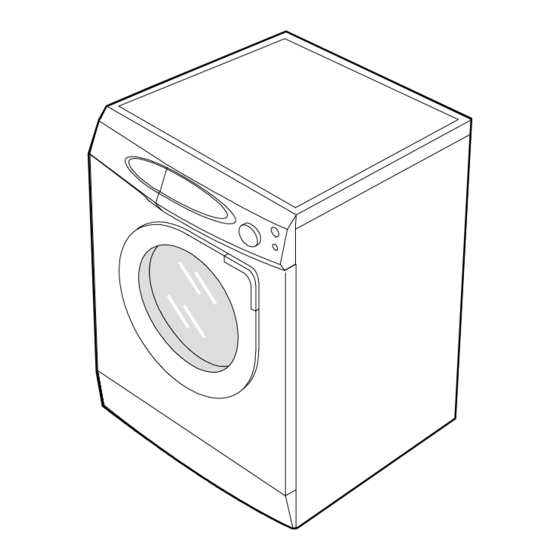
2. Overview of the Washing Machine... -
Page 5: Overview Of The Control Panel
3. Overview of the control panel P1091/P1291 P8091 1. Detergent dispenser Display panel Displays the remaining wash cycle time, error messages and cancel -. 3. Temperature selection button Press the button repeatedly to cycle through the available water temperature options. (cold water, 30 °... -
Page 6: General Error Function
4. General Error Function • When an error occurs, this function starts to keep generating error melody sounds and displays error indicators as shown in the followings per corresponding error by blinking in 0.5sec intervals until the error status is completely cleared out. -
Page 7: Trouble Diagnosis
5. Trouble Diagnosis ♦ As the micom washing machine is configured of a complicated structure, there might be a need for a service call. The information below is prepared for exact trouble diagnosis and suitable repair guide. Caution for the Repair and Replacement Please follow instructions below for trouble diagnosis and parts replacement. - Page 8 5-1. Trouble Diagnosis Item Cause and treatment The power is not supplied - Is the PCB connector connected well? - Is the voltage normal? - Is the power supply plug connected well? - Is the noise filter connected well? - Is the secondary output of the power supply transformation normal? - Is the fuse disconnected? (option) ï...
-
Page 9: Test Mode
6. Test Mode 1. Driving Compartment Test Mode A. Hold down "2" and "1" keys simultaneously and then press (POWER S/W) on. (Display shows 'tE') Hold down "1" and "2" keys simultanesously (each processing for 0.3sec) and then press (POWER S/W) on. -
Page 10: Designation Of Main Components
7. Designation of Main Components 7-1 Normal / Reverse Revolution of Motor and R. P. M. Control 1 2 3 4 5 6 7 8 9 10 Rotor Stator coil Rotor STATOR Stator coil WASHING MOTOR <Figure1> <Figure2> PROTECTOR "H" STATOR(5.1) STATOR(5.1) ROTOR(8.9) - Page 11 7-4 ASSY-TUB BACK INNER-BEARING OUT-BEARING OIL-SEAL (unit : mm) TYPE INNER-BEARING(A) OUT-BEARING(B) OIL-SEAL(C) Assy-Housing Bearing(D) REMARKS 43.9 DC97-00214B P1091/P1291 24.3 DC97-00214K P8091 7-5 ASSY- DRUM (unit : mm) TYPE CODE-NO. REMARKS 44.7 DC97-01463A Lifter type P1091/P1291 DC97-01463B Lifter type P8091...
-
Page 12: Pcb Schematic Diagram
8. PCB Schematic Diagram... -
Page 13: Pcb Circuit Diagram
8. PCB CIRCUIT DIAGRAM... - Page 14 8. PCB List LOCATION NO. CODE NO. DESCRIPTION SPECIFICATION Q'TY REMARK WDD01 1401-001007 THYRISTOR-TRIAC 10A,800V,20uA,300V/uS,TO-220AB TRIAC1 WDD01 1401-001024 THYRISTOR-TRIAC 2A,800V,20UA,300V/US,TO-220F TRIAC2,3,4,5,6 WDD02 0402-001023 DIODE-BRIDGE RBV1506,600V,15A,SIP-4 WDD03 3501-001163 RELAY-MINIATURE 12VDC,200MW,5000MA,1FORMA,10MS,5MS RELAY6 WDD04 3501-001156 RELAY-POWER 12VDC,0.53W,16000MA,1FORMA,20MS,10MS RELAY1 WDD05 0402-000137 DIODE-RECTIFIER 1N4007,1000V,1A,DO-41,TP D13,D16~D19,D23 WDD06 0504-001045 TR-DIGITAL...
-
Page 15: Assemble And Disassemble
9. Assemble and Disassemble 1. ASSí Y-COVER TOP 1) Remove two screws fixing the top-cover to back side. SCREW 2) Push the top-cover back about 15mm and pull it up. 3) It's possible to exchange and service the trans former, the pressure-senser, the noise-filter and the water valve. - Page 16 9. Assemble and Disassemble 3. BELT 1) Remove the top-cover. 2) Disassemble and assemble the belt. 3) Check that the belt is located at center of the motor-pulley. <When assembling the belt> PULLEY Hook the belt onto the motor pulley 1) and place it around the pulley 2).
-
Page 17: Tools For Disassembly And Assembly
10. Tools for Disassembly and Assembly TOOL 10mm Heater (1) 13mm Motor (1), Balance (5) ① Box driver 17mm 2 holes on each left and right of the shock absorber 19mm 1 Pulley hole Replaceable for the box driver. Double-ended 10, 13 ②...