
Related Manuals for Fluke TS54 TDR


Summary of Contents for Fluke TS54 TDR
- Page 1 54 TDR 53 PRO Test Sets Users Guide PN 3836384 August 2011, Rev. 1, 12/11 ©2011 Fluke Corporation. Printed in China. All product names are trademarks of their respective companies.
- Page 2 MH and Li-Ion batteries, cables or other peripherals are all considered parts or accessories. The warranty extends only to the original buyer or end user customer of a Fluke Networks authorized reseller, and does not apply to any product which, in Fluke Networks’ opinion, has been misused, abused, altered, neglected, contaminated, or damaged by accident or abnormal conditions of operation or handling.
-
Page 3: Table Of Contents
Contents Title Page Overview of Features ............................1 Registration .................................1 Contacting Fluke Networks ..........................2 Safety Information ..............................2 Physical Characteristics ............................3 Housing ................................3 Belt Clip ................................3 Test Leads ..............................3 Battery ................................3 Speaker and Speakerphone Microphone ....................3 Display and Keypad .............................5 How to Turn the Test Set On and Off ......................11 How to Use the Monitor and Talk Modes .......................11... - Page 4 Test Set Timeout ............................23 Speaker and Handset Receiver Volume for Talk Mode ................24 Velocity of Propagation (VOP) ........................24 Factory Defaults ............................25 Time Domain Reflectometry (TDR) Technology (TS54 TDR) ................25 VOP Variations ..............................27 Frequently Asked Questions ..........................28 Maintenance ..............................29 Cleaning ..............................29 If the Test Set Gets Wet ..........................29...
-
Page 5: Overview Of Features
• Overview of Features Microphone mute • Pause key • The TS54 TDR and TS53 PRO Professional Series Test Reverse polarity indication Sets are analog test telephones used by installers, • Two-way speakerphone repair technicians and other authorized personnel to •... -
Page 6: Contacting Fluke Networks
Do not connect the test set to lines that have more Anywhere in the world: +1-425-446-4519 than 140 V dc. Visit the Fluke Networks website for a complete list of • The test set meets IEC Measurement Category I. phone numbers. -
Page 7: Physical Characteristics
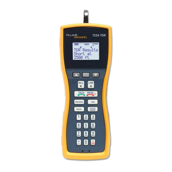
If the test set does not operate properly, first replace the battery and try it again before you Housing send the test set to Fluke Networks for repair. See Figure 1. A 9 V alkaline battery must be installed for the test set The test set housing is made of high-impact plastic. - Page 8 TS54TDR/TS53 PRO Test Sets Users Guide LCD display Handset receiver Keypad Handset microphone and Speakerphone microphone Belt clip Belt clip protector Speaker Headset jack with weather-resistant plug Battery door Test leads with alligator clips GOL02.EPS Figure 1. Physical Characteristics (TS54 TDR shown)
-
Page 9: Display And Keypad
Physical Characteristics Display and Keypad See Tables 1 and 2. The test sets have an LCD display and a keypad that are recessed into the housing. The recessed bezel protects the keypad and helps prevent accidental key presses. Table 1. Display Icons GOL03.EPS When the 9 V battery is nearly discharged, no bars are shown on the battery icon on the display. - Page 10 TS54TDR/TS53 PRO Test Sets Users Guide Table 1. Display Icons (continued) The polarity icon shows when the polarity of the dc voltage across the line’s Tip and Ring wires is reversed. If you connect the red clip to a more positive voltage than the black clip (reverse polarity), shows on the display.
- Page 11 Physical Characteristics Table 2. Keys GOL15.EPS 1 2 3 Use the numeric keypad to dial telephone numbers and select some functions. The numeric keypad has 12 standard dialing keys including the star ( ) and the pound ( ) keys. 4 5 6 To make the test set go off-hook when there is data on the line, press .
- Page 12 To turn on the microphone, press again. TS54 TDR and TS53 PRO only: When the test set is off-hook and is in Speakerphone mode, you can press to turn off the speakerphone’s microphone and temporarily put the test set into a Receive-Only Loud Speaker mode.
- Page 13 Physical Characteristics Table 2. Keys (continued) The speaker key turns the speaker on the back of the test set on and off. It operates in both Talk and Monitor modes. When the speaker is on, shows on the display. In Monitor mode when you use the test set as a handset, press to turn on the speaker so you can monitor a line while you work at a distance from the test set.
- Page 14 : Lets you edit numbers in the phonebook. See "Program Speed Dialing Numbers" on page 15. • (TS54 TDR): Lets you change the Line Verification and VOP settings for the TDR. See "Line Verification" on page 18 and "VOP" on page 18. •...
-
Page 15: How To Turn The Test Set On And Off
How to Turn the Test Set On and Off How to Turn the Test Set On Monitor Mode and Off To put the test set in Monitor mode, press In Monitor mode, the test set is always on-hook. The To turn on the test set, press . -
Page 16: Test For Data On The Line (Ts53 Pro)
TS54TDR/TS53 PRO Test Sets Users Guide Test for Data on the Line (TS53 PRO) Note The test set will not go off-hook if the line On the TS53 PRO test set, press while in Monitor voltage exceeds 140 V dc. mode to do a test for data on the line. -
Page 17: Data Lockout Operation
How to Use the Monitor and Talk Modes Data Safe Practices Data Lockout Operation Always monitor the line for an audible signal before With the increase in high capacity data lines in the attempting to go off-hook to draw dial tone. The data distribution system comes the greater risk of disrupting detect circuitry on the test set is designed to detect data services when working on analog lines. -
Page 18: Data Lockout Override
The TS54 TDR and TS53 PRO are designed for use by Outside Plant and Central Office technicians in But in some cases the operator must go off-hook on a... -
Page 19: Program Speed Dialing Numbers
How to Use the Monitor and Talk Modes Program Speed Dialing Numbers Notes The location of the number in the phonebook The test set has nine memory locations for speed dial is the recall number. For example, the first numbers. Each location stores up to 23 digits. If you try number in the phonebook has the recall to enter more than 23 digits, only the first 23 are number “1”. -
Page 20: Storing The Number You Are Calling
TS54TDR/TS53 PRO Test Sets Users Guide Storing the Number You are Calling Press . The test set goes off-hook, then dials the number. After you dial a number, you can save it in one of the memory locations for the speed dialing function: DTMF Digit Grabbing Connect the test set to a working telephone line. -
Page 21: Visual Anac Mode
Visual ANAC mode is for service provider use 3,000 ft (914 m). See “"Time Domain Reflectometry only. Visual ANAC is not available in all regions. (TDR) Technology (TS54 TDR)" on page 25 for information on how the TDR operates. A visual Automatic Number Announcement Circuit... -
Page 22: How To Change The Length Units
TS54TDR/TS53 PRO Test Sets Users Guide How to Change the Length Units To turn on the Line Verification function: The TDR shows length measurements in feet or meters. Press To change the unit of measurement: Press to put the flashing cursor next to Press then press Press... -
Page 23: If The Tdr Shows Unusual Or Unstable Length Measurements
Using the Toner (TS54 TDR) If the TDR Shows Unusual or Unstable Finding a Cable Length Measurements To find a cable: Devices connected to the line can make the TDR show Turn on the test set. unusual or unstable measurements. Such devices... - Page 24 Connect to wires from different pairs, if possible. Punchdown block RJ11 jack GOL10.EPS Figure 2. How to Make Connections for the Toner (TS54 TDR) Find the correct bundle Find a cable Find a cable behind a wall in a bundle GOL11.EPS...
-
Page 25: Using The Smarttone Function
Using the Toner (TS54 TDR) Using the SmartTone Function To use the SmartTone function to identify a wire pair: Turn on the test set, then connect it to a wire pair in the cable. Make sure that the test set shows 0 VDC. -
Page 26: Configuring Your Test Set
TS54TDR/TS53 PRO Test Sets Users Guide Configuring Your Test Set To go back to the previous menu, press . Or, Back press until shows, then press The test set stores all settings in non-volatile memory. The settings do not change if you change the battery. Pause Duration When you enter numbers into the speed-dialing How to Select Tone or Pulse Mode... -
Page 27: Display Backlight Timeout
Configuring Your Test Set To set Receive-Only Loud Speaker as the default mode To save your selection before you exit or go back for the speaker: to the main menu, press . The display shows Saved Press To go back to the previous menu, press . -
Page 28: Speaker And Handset Receiver Volume For Talk Mode
The test set uses the VOP value to calculate length for by approximately 1.5%. the TDR function. See "Time Domain Reflectometry (TDR) Technology (TS54 TDR)" on page 25. Do steps 2 through 4 again, until the length measurement is correct. -
Page 29: Factory Defaults
Time Domain Reflectometry (TDR) Technology (TS54 TDR) Factory Defaults Time Domain Reflectometry (TDR) Technology (TS54 TDR) You can set all programmable features to their original, factory settings. This function does not delete stored A time domain reflectometer senses reflections of telephone numbers. - Page 30 TS54TDR/TS53 PRO Test Sets Users Guide Pulse from the test set Time Open Time Reflection Pulse from the test set Short Time Time Reflection GOL05.EPS Figure 5. Signal Reflections from an Open and a Short...
-
Page 31: Vop Variations
VOP Variations VOP Variations Table 3. VOP Values and Maximum Length for Specifically Identified Cables Typically, cable manufacturers do not tightly control Maximum the VOP of cables. The VOP of the same type of cable Length Cable from different boxes or from different manufacturers can have large variations. -
Page 32: Frequently Asked Questions
TS54TDR/TS53 PRO Test Sets Users Guide Table 4. VOP Values for Other Cables A: If the cable has more than two conductors, and a short exists at the far end between one of the Cable Type conductors you are connected to and a conductor you are not connected to, the displayed length will be the Twisted Pair, Gel Filled 19 AWG sum of the lengths of the conductors joined by the... -
Page 33: Maintenance
This resets the test set. Use the same battery if you know it is good or use a new battery if you are not sure. If it still does not operate, contact Fluke Networks Technical Support. -
Page 34: Replacing The Belt Clip
You can replace the protector if You can replace the belt clip if it is damaged. To order a it is damaged: replacement belt clip, contact your local Fluke Networks authorized distributor. Remove the belt clip as described in the previous section. -
Page 35: Replacing The Test Leads
You can replace a worn out or damaged test lead. To leads. get a replacement test lead, contact your local Fluke Networks authorized distributor. Put the lug of the new test lead through the hole in the housing, then pull approximately 1 inch ... -
Page 36: Accessories
HEADSET-TS Hanger kit (magnetic and clip-on hangers for the test set) TEST-SET-HANGER-TS 1. All accessories are for models TS54 TDR and TS53 PRO. 2. When you use these test leads, the TDR accuracy specifications do not apply. Specifications Rotary Dial Output Pulsing Rate 10 pps ±1 pps... -
Page 37: Software Notice
Software Notice Memory Dialing LCD function -13°F to 140°F (-25°C to 60°C) Memory Capacity 9 speed dial memories plus Storage -22°F to 150°F (-30°C to 66°C) one last number redial Altitude To 10,000 ft. (3,000 m) max memory Relative Humidity 95% to 30°C Digit Capacity 23 digits per memory... - Page 38 TS54TDR/TS53 PRO Test Sets Users Guide...