
Related Manuals for Fisher & Paykel GWL03US


Summary of Contents for Fisher & Paykel GWL03US
-
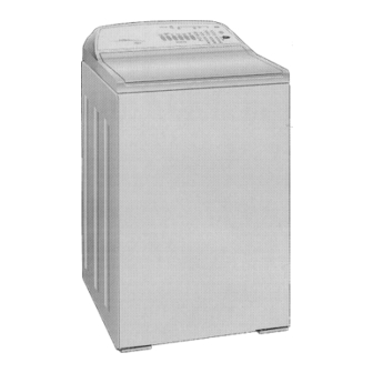
Page 1: Smart Drive Electronic Washing Machine
SMART DRIVE ELECTRONIC WASHING MACHINE MODEL GWL03US 120 Volt 60 Hz Fisher & Paykel Appliances Inc 27 Hubble, Irvine, California, CA92618, USA, Ph: 949 790 8900, Fax: 949 790 8911 426348... -
Page 3: Table Of Contents
C O N T E N T S SMART DRIVE ELECTRONIC WASHING MACHINE..............1 1.0 SPECIFICATIONS........................6 FINISH ............................6 DIMENSIONS..........................6 2.0 UNPACKING..........................8 3.0 INSTALLATION ........................8 HOT WATER TEMPERATURE....................9 DRAINING ..........................9 4.0 INTRODUCTION ........................10 5.1 ELECTRONICS SYSTEMS ....................10 5.1.1 MOTOR..........................11 5.1.2 ROTOR POSITION SENSOR MODULE...............11 5.1.3 MOTOR CONTROLLER MODULE ................12 5.1.4 DISPLAY MODULE .......................12 5.1.5 PRESSURE SENSOR ......................12... - Page 4 TO USE DELAY START......................28 7.7 FABRIC SOFTENER DISPENSER ..................29 7.8 USER FAULTS........................30 8.0 DEMONSTRATION MODE....................31 TO SELECT DEMONSTRATION MODE................31 9.0 DIAGNOSTIC MODE......................32 TO SELECT DIAGNOSTIC MODE..................32 9.1 LED TEST..........................32 9.2 SWITCH TEST ........................32 9.2.1 LID SWITCH ........................32 9.2.2 OUT OF BALANCE SWITCH..................32 9.2.3 LOCATION SWITCH .....................33 9.3 DRAIN PUMP TEST......................33 9.4 WATER VALVE TEST......................33...
- Page 5 132. (10000 100) SINGLE CURRENT TRIP ................41 133. (10000 101) REPETITIVE CURRENT TRIP ..............41 136. (10001 000) MOTOR STALL...................42 160. (10100 000) BASKET ENGAGED...................42 10.3 MOTOR CONTROLLER VOLTAGE CHECK..............43 10.4 DIAGNOSTIC FLOW CHART....................44 11.0 REMOVING AND REFITTING OF ELESTRONIC MODULES ........45 11.1 ESD PRECAUTIONS ......................45 11.2 CONNECTORS........................46 11.2.1 EASY OFF CONNECTORS..................46...
-
Page 6: Specifications
1.0 SPECIFICATIONS FINISH Cabinet Prepaint (Polyester) Lid Polypropylene Console Polypropylene Basket stainless steel (grade 430T) Tub Polypropylene Agitator Polypropylene Cover Polypropylene Touch Panel Polypropylene DIMENSIONS Height Floor to Lid Lid closed 35 ½“ – 36½ “ (900mm – 930mm) Lid open Add 18”... - Page 7 Water fill temp (Factory Settings) 120 o F (49 o C) 105 o F (40 o C) Hot/Warm 95 o F (35 o C) Warm 85 o F (29 o C) Warm/Cold Cold as per cold water supply temperature. Recommended inlet hot water temperature not to exceed 150 o F (65 o C) Wash Motor Electronically commutated direct drive DC Motor...
-
Page 8: Unpacking
2.0 UNPACKING 1. Remove the outer packing, leave the washer standing upright on the cardboard bottom. 2. Lift the lid and remove the cardboard shipping pack from under the lid. 3. Remove the hoses and accessories. 4. Rotate the agitator anti-clockwise for 3 revolutions to unscrew the red shipping restraint from the base of the washer. -
Page 9: Hot Water Temperature
5. Place the screened sealing washers (from the accessory kit) into the straight end of the inlet hoses and connect to the faucets. Turn on the water and check the hose connections for leaks. 6. Move the washer into its final position. We suggest a minimum clearance of ¾... -
Page 10: Introduction
4.0 INTRODUCTION The washer design has a number of unique features not found on any other washer. These will be explained in the following sections. 5.1 ELECTRONICS SYSTEMS The washer electronics consists of 4 main parts: a) Motor b) Rotor Position Sensor c) Motor Controller Module d) Display Module e) Pressure Sensor... -
Page 11: Motor
5.1.1 MOTOR The motor is a 3 phase, 42 pole, DC brushless motor. Rotation of the motor is controlled by a microprocessor located in the Motor Controller Module. The Motor consists of a STATOR (stationary part) and ROTOR (rotating part). 5.1.2 ROTOR POSITION SENSOR MODULE Fitted to the Stator is the Rotor Position Sensor Module. -
Page 12: Motor Controller Module
5.1.3 MOTOR CONTROLLER MODULE The Motor Controller Module contains the circuits needed to control the water valves, pump and the main motor. It contains a microprocessor that controls these functions as well as accepting signals from the Rotor Position Sensor and Display Module. The Motor Controller Module and Display Module are continuously communicating with each other, passing information back and forth on the required wash actions and diagnostic data. -
Page 13: Water Valves
5.1.7 WATER VALVES The washer is fitted with an automatic water temperature fill system. The electronics control the water valves so that a constant water temperature is achieved in the tub irrespective of the temperatures and pressures of the household hot and cold water systems. This system will also compensate for changes in pressure and temperature during the washer’s fill cycle. -
Page 14: Mechanical System
5.2 MECHANICAL SYSTEM 5.2.1 DIRECT DRIVE In this washer the motor shaft is connected directly to the agitator. The DIRECT DRIVE motor has eliminated the need for pulleys, belts, gearboxes and other electro-mechanical items used in other designs. The single shaft design also reduces the number of seals. 5.2.2 FLOATING BASKET During spin, the agitator and basket have to be coupled together and turn as a single unit, whilst in agitate the agitator and basket have to be free to rotate independently. -
Page 15: Automatic Water Level System
Detection of Basket Float Off Point During fill the basket rotates to ensure that the clothes are evenly saturated with water. Whilst the tub is filling, the agitator will occasional stop and commence a number of special agitate actions. During these actions the washer determines if the basket has floated. If it has, the microprocessor can now determine the correct water level and will continue filling to that level. -
Page 16: Lid Switch
5.2.5 LID SWITCH Lid opening and closing is detected by a reed switch located under the right hand side of the cover, approx. 5” (125mm) from the front. The reed switch is activated by a magnet which is moulded into the lid. A protrusion can be seen on the underside of the lid where the magnet is located. If the lid is raised the washer will stop and go into PAUSE. -
Page 17: Option Adjustment Mode
6.0 OPTION ADJUSTMENT MODE The owner can customise the washer to there own preference. This is done in the OPTION ADJUSTMENT MODE. The features that can be adjusted are: a) Wash Water Temperature b) Rinse Options c) End of Cycle Warning Beeps d) Volume of water used in the Water Saver Option e) Auto Water Level Adjustment To Select the OPTION ADJUSTMENT MODE... -
Page 18: Wash Water Temperature
6.1 WASH WATER TEMPERATURE The water temperature of each of the wash temperature settings can be changed. METHOD OF SETTINGS THE WASH TEMPERATURE 1. Select the OPTION ADJUSTMENT MODE by pressing and holding down the START/PAUSE button, then pressing the POWER button. 2. -
Page 19: Example Of Adjusting Wash Temperature
EXAMPLE OF ADJUSTING WASH TEMPERATURE Adjust Warm/Hot temperature to 109 o F (43 o C). 1. To select the OPTION ADJUSTMENT MODE by pressing and holding down the START/PAUSE button, then press the POWER button. 2. To select the WARM/HOT temperature. Press the WASH TEMPERATURE UP button once. - Page 20 3. Press the ADVANCE button twice. The final Rinse LED will be on. This is the 109 o F LED as shown on Table 2. 4. Press the POWER button to return to normal operation.
-
Page 21: Rinse Options
6.2 RINSE OPTIONS The washer may be used in a large number of different installations. To cater for these variations the Rinse type can be changed. First Rinse Description Comments RINSE Spray Rinse Clothes have water sprayed Factory Setting. Gives the OPTION (1) over them as they are spinning. -
Page 22: End Of Cycle Warning Beeps
6.3 END OF CYCLE WARNING BEEPS The washer finishes each cycle by sounding a series of warning beeps. In some circumstances the user may wish to increase the number of beeps or eliminate them altogether. METHOD OF ADJUSTING THE NUMBER OF END OF CYCLE WARNING BEEPS 1. -
Page 23: Volume Of Water Used In The Water Saver Option
6.4 VOLUME OF WATER USED IN THE WATER SAVER OPTION You can increase or decrease the volume of water used during the Water Saver option. 1. Select the OPTION ADJUSTMENT MODE by pressing and holding down the START/PAUSE button, then pressing the POWER button. 2. -
Page 24: Auto Water Level Adjustment
6.6 AUTO WATER LEVEL ADJUSTMENT If the user is not satisfied with the level that the washer fills to on automatic water level, the washer can be programmed so that there will be a greater chance of the washer selecting a higher water level. -
Page 25: Operation / Use & Care
7.0 OPERATION / USE & CARE 7.1 WASH CYCLES The washer has a number of wash cycles and features. The following is an explanation of each cycle and feature. 7.1.1 WASH CYCLE TIMES Wash Regular Heavy Delicate Permanent Wool Progress Duty Press Fill... -
Page 26: Agitator Profile Comparisons
7.1.2 AGITATOR PROFILE COMPARISONS The washer has 15 different agitate actions. This type of action used depends on the wash cycle and water level. Water level Regular Heavy Delicate Permanent Wool Cycle Cycle Duty Cycle Cycle Cycle Action 10 Action 15 Action 5 Action 10 Action 5... -
Page 27: Water Saver Option
Water saver in the Wool, Delicate or Permanent Press cycle. AMOUNT OF WATER USED IN THE WATER SAVER RINSE MODEL SHOWER RINSE SPRAY & DEEP RINSE GWL03US 16 US gals 30 US gals 60 Litres 115 Litres Approximate figures for high water level, rinse cycle only. -
Page 28: Delay Start
7.6 DELAY START In this mode the washer will start after the appropriate delay time. The flashing of the wash progress LED will stop when the DELAY START is selected. TO USE DELAY START 1. Select your wash cycle and options. 2. -
Page 29: Fabric Softener Dispenser
7.7 FABRIC SOFTENER DISPENSER The fabric softener goes into the dispenser on the top of the agitator. The dispenser is designed to automatically deliver softener into the final rinse. This occurs on the Heavy Duty, Regular and Wool Cycles. 1. Fabric softener remains in the dispenser cup during the fill, agitate and drain phase of the was program. -
Page 30: User Faults
7.8 USER FAULTS There are a number of faults caused by incorrect installation or operation which the washer can detect and sound a warning. These faults can be corrected by the user. The washer signals these faults by flashing an LED and sounding the beeper. WASHER IS GIVING A SHORT POSSIBLE SOLUTIONS BURST OF BEEPS AND... -
Page 31: Demonstration Mode
8.0 DEMONSTRATION MODE This feature is designed for in store demonstration purposes. The washer can draw attention to itself with flashing LED’s. In this mode, rotation of the basket can not occur. TO SELECT DEMONSTRATION MODE 1. Press and hold down the ADVANCE button, then press the POWER button. During the DEMONSTRATION MODE the LED’s will be flashing on/off in a particular sequence. -
Page 32: Diagnostic Mode
9.0 DIAGNOSTIC MODE The washer is fitted with a diagnostic system designed to help the serviceman test the washer and obtain information that will assist in locating a fault. TO SELECT DIAGNOSTIC MODE 1. Press and hold down the WASH TEMPERATURE DOWN button, then press the POWER button. -
Page 33: Location Switch
9.2.3 LOCATION SWITCH The Location switch is inside the Display Module. It is activated automatically by a plastic pillar moulded into the console. (a) When the Display Module is correctly fitted to the console, the switch is activated, and the SPIN LED will be ON when the SWITCH TEST MODE is selected. -
Page 34: Re-Cycle Feature
9.6 RE-CYCLE FEATURE WATER LEVEL UP button turns the RE-CYCLE feature on/off. MEDIUM WATER LEVEL LED ON - RECYCLE ON MEDIUM WATER LEVEL LED OFF - RE-CYCLE OFF (Factory setting). At the end of servicing, the washer may require an extended test where the washer can be left to complete a number of wash cycles. -
Page 35: Fault Mode
10.0 FAULT MODE 10.1 BINARY CODE The Fault Codes are displayed using a BINARY NUMBERING SYSTEM. By using this system each unique fault code can be given a number. Each fault code is listed under this number in the FAULT CODE DESCRIPTIONS Section. Each LED represents a certain number (see above). -
Page 36: Fault Code Descriptions
10.2 FAULT CODE DESCRIPTIONS Failures in operation are diagnosed by the washer. It will shut down the washer and display a fault code on the CYCLE PROGRESS LED’s whilst continuously beeping. If a fault condition has occurred, first remove the power plug from the wall socket for at least 15 seconds, and then insert it again. -
Page 37: 00001 010) Temperature Sensor Error
10. (00001 010) TEMPERATURE SENSOR ERROR F (-10 o C). The temperature sensor may be open circuit or the ambient temperature is below 18 Action Change the Motor Control Module. 11. (00001 011) PRESSURE SENSOR FAULT While measuring the water level the Motor Control has detected a negative pressure. This may have been caused by reconnecting the pressure tube to the pressure sensor while the tub has been partly filled with water. -
Page 38: 00100 110) Pressure Sensor Fault
Action 1. Check that the drain hose has not been kinked, squashed or blocked in any way. 2. Check length of drain hose. A 39" (1000mm) extension hose of the same diameter fitted to the existing drain hose is the maximum allowable length. 3. -
Page 39: 00101 001) Temperature Sensor Fault
3. Next check that the pressure tube has not come off and that it is not kinked. 4. Replace Motor Control Module 41. (00101 001) TEMPERATURE SENSOR FAULT The temperature sensor is measuring temperatures above 230 o F (110 o C). Action 1. -
Page 40: 00110 000) Hot And Cold Valve Faulty
Action 1. Check that there are no clothes or other foreign objects preventing the clutch from re-engaging. 2. Next check that the pressure tube has not come off and that it is not kinked. 3. Replace Motor Control Module. 48. (00110 000) HOT AND COLD VALVE FAULTY The Motor Control Module diagnostic circuit has deducted that both the hot and cold valve are faulty. -
Page 41: 107. (01101 011) Motor Control Module Reset Error
107. (01101 011) MOTOR CONTROL MODULE RESET ERROR The Display Module has detected that the Motor Control Module has reset when it should not have. This can be due to a Motor Control Module supply disturbance or microprocessor failure. Action Replace Motor Control Module. -
Page 42: 136. (10001 000) Motor Stall
136. (10001 000) MOTOR STALL The Motor Controller has been unable to start the motor. Action 1. Measure/check the motor harness connectors and motor for discontinuity. This can be done by taking a resistance measurement between phases of the motor harness at the Motor Control Module end. -
Page 43: Motor Controller Voltage Check
10.3 MOTOR CONTROLLER VOLTAGE CHECK... -
Page 44: Diagnostic Flow Chart
10.4 DIAGNOSTIC FLOW CHART... -
Page 45: Removing And Refitting Of Elestronic Modules
11.0 REMOVING AND REFITTING OF ELESTRONIC MODULES CAUTION CERTAIN INTERNAL PARTS ARE INTENTIONALLY NOT GROUNDED AND MAY REPRESENT A RISK OF ELECTRIC SHOCK ONLY DURING SERVICING. DO NOT CONTACT THE FOLLOWING PARTS WHILE THE WASHER IS ENERGISED: WATER VALVE BRACKETS, PUMP MOUNTING BRACKET, BOTTOM PANEL. -
Page 46: Connectors
11.2 CONNECTORS 11.2.1 EASY OFF CONNECTORS The Motor, Water Valves and Out of Balance Switch use easy off connectors. These types of connectors require low insertion and removal force provided they are removed by gripping the insulator housing. DO NOT try to remove these connectors by pulling on the wire. This can result in damage to the lead and connector. -
Page 47: Access To Console Area
11.3 ACCESS TO CONSOLE AREA 1. Remove 2 screws from the rear of the console. 2. The console can now be raised for access to the Motor Controller Module, Display Module, Inlet Chamber and associated wiring. 11.4 DISPLAY MODULE 1. Connect a Static wrist strap to ground. 2. -
Page 48: Motor Controller Module
11.5 MOTOR CONTROLLER MODULE If possible, record the user’s preferred options before removing the MOTOR CONTROLLER MODULE. This will allow you to return the machine to the users original programming. 1. Connect an anti-static wrist strap to ground. 2. Unplug the harnesses (A) Display Module (B) Water Valves (C) Power Plug... -
Page 49: Inlet Chamber & Water Valves
11.6 INLET CHAMBER & WATER VALVES 1. Remove Motor Controller. Refer 11.5. 2. Turn off faucets and remove inlet hoses. Take care not to spray water into console area. 3. Remove the two screws located between the inlet valves and remove the screw from the top os the inlet chamber. -
Page 50: Diagnostic Test
1. Refer Section 13.3 for motor removal. 2. Unclip the rotor position sensor Module from the stator and slide it out. 3. When fitting, line up the arrows on the Rotor Position Sensor and Stator. Slide the Rotor Position Sensor into the Stator poles until the clip locks into the notch on the other side of the Stator. -
Page 51: Mechanical Disassembly & Reassembly
12.0 MECHANICAL DISASSEMBLY & REASSEMBLY 12.1 BEARING REPLACEMENT KIT... -
Page 52: Mechanical Disassembly Procedure
12.2 MECHANICAL DISASSEMBLY PROCEDURE 1. Isolate from the power supply. 2. To remove the lid, open it to the upright position and lift it clear. 3. Remove the 2 screws from the rear of the console. Raise the console for access to the Motor Controller Module, Display Module, Inlet Chamber, Water Valves and associated wiring. - Page 53 5. Disconnect Display Module plug (A). Disconnect the motor/pump harness plug (B), Rotor Position Sensor plug (C). Remove the pump ground lead (D). Remove the power plug (E). Remove the rubber bungs from the back of the cord set clamp screw holes, undo the 2 screws which are holding the cord clamp.
- Page 54 The basket may now be lifted clear. (If the basket is not easy to lift clear, then remove the three driven spline retaining screws and remove the driven spline. Then pull the drive spline off the shaft and lift out the basket). 9.
- Page 55 10. Feed the drain hose inside the cabinet. Clip the drain hose fixture over the tub with the attached hook. 11. Remove the remaining three suspension rod assemblies.
- Page 56 12. The tub can be lifted clear of the cabinet. Drain the water from the tub, then invert the tub, enabling servicing of the motor and pump. Alternatively lay the cabinet on its back, on protective material, and slide the tub assembly out, but note that approximately ¼ gal (1 litre) of water must be removed from the pump sump before laying the cabinet on its back.
- Page 57 13. Unscrew the rotor by using a 5/8 “ (16mm) socket. Lift the rotor clear, and place in a plastic bag. WARNING: Before removing the rotor, have a plastic bag or suitable clean container to place the rotor in to avoid contamination. The rotor has strong magnets and can attract metal objects which can damage the motor when reassembled.
- Page 58 16. The motor shield can now be lifted off the base of the tub. 17. To remove the pump, release the pump retaining clip. Turn the pump anti-clockwise, lift it clear and disconnect the wiring terminals.
- Page 59 18. Remove the two screws securing the wiring duct to the tub. 19. Remove the drain hose clamp. Twist the drain hose in an anti-clockwise direction to release.
- Page 60 20. If changing the tub, the pump mounting plate can be removed at this stage by unscrewing the 4 securing bolts. 21. Remove the clamp from the pressure tube and pull the tube off the spigot on the pressure chamber. Unclip the pump harness and then remove the drain hose assembly. 22.
- Page 61 23. Fit the spline tool over the shaft. Remove the 1 ¼ “ AF shaft retaining nut. 24. Lay the tub on its side before removal of the shaft. This ensures that the shaft does not fall directly onto the floor.
- Page 62 25. The shaft can be removed in one direction only, towards the inside of the tub. Remove the shaft from the tub. Should this shaft be difficult to remove, use pullers and mandrel. Refit the stator motor clamp plate onto the tub and secure with the stator mounting bolts. Use the stator clamp plate to hold the legs of the pullers in place.
-
Page 63: Mechanical Reassembly Procedure
12.3 MECHANICAL REASSEMBLY PROCEDURE 1. The bearing must be inserted separately with the inner bearing fitted first, and pulled down with the bearing tool, onto the shoulder in the bearing housing. IMPORTANT: There must be no gap between the bearing outer race and the shoulder of the aluminium extrusion. - Page 64 5. Refit Drain Hose Outlet to the tub. Note: Ensure the lugs on the elbow are located underneath the pump bracket. Clamp into position. 6. Fit the pump motor mounting bracket and clip (if removed). 7. Secure the wiring/drain duct assembly onto the tub using two screws.
- Page 65 8. Turn the pump motor clockwise when refitting it onto the bayonet fixture. Check that the pump retaining clip has clicked into place. 9. Connect the wiring to the pump. Clip the pump harness into the securing clips.
- Page 66 10. Fit the wires to the stator before locating the stator into position. Check that the wiring is correct – see markings on the stator. 11. Grease the stator side of the clamp plates and around the inside section of the stator that fits over the bearing, with any multi purpose grease.
- Page 67 12. Refit the clamp plate onto the stator and tighten the four 3/8 “ bolts to a torque of 44 in.-lb. (5 Nm). Note: The stator should have some slight radial movement on the resilient mounts of approximately 1/32 “ – 1/16 “ (0.5 – 1mm) when correctly tightened as shown by the arrows on the diagram below, and should have minimal axial play (rocking movement) of 1/32 “...
- Page 68 22. Clip the right rear suspension assembly onto the tub. Locate the wiring and pressure tube into the corner bracket as shown below, then clip the corner bracket into place. NOTE: Check that the wiring does not cross and that the pressure tube is not pinched. 23.
- Page 69 24. Refit the front left suspension assembly. 25. Refit the drive spline and driven spline to the basket. 26. Lift the basket into place, slide into position and rotate to ensure that the clutch and spline are located into place. Then push the basket fully down. 27.
- Page 70 31. Reconnect the wiring connections onto the appropriate components. Motor/Pump plug (A), Rotor Position Sensor plug (B) pump ground and cord set ground (C). Reconnect the power cord clamp and secure with 2 screws. Note: ENSURE THAT THE WIRING INSTALLATION IS CORRECT. Refer to diagrams below.
-
Page 71: Selected Ares Of Service
13.0 SELECTED ARES OF SERVICE 13.1 PUMP BLOCKAGE Always refer to the electronic diagnostics on the control panel for any fault symptom. a) Remove the front inspection panel by inserting a screwdriver into the slot and turn anti- clockwise 1/8 of a turn. Pull panel outwards and remove. b) Advance to SPIN and attempt to flick start the fan on the pump motor. -
Page 72: Complete Pump Failure - Burnt Out
d) If unable to flick start, remove the lid, remove the agitator, and empty the water from the basket. Remove the two inlet hoses and the cord set from the cover. Remove the rubber buffers and two front covers screws, tilt the cover back. Do not exert too much pressure on the cover locating tags. -
Page 73: Motor
13.3 MOTOR To remove the motor: a) Disconnect from the electrical power and water supplies. b) Feed the drain hose back through the top hole in the drain hose fixture. c) Lay the washer on its back on protective material. Ensure that the washer is slightly raised at the top to prevent residual water in the tub from spilling out. - Page 74 h) To refit motor. Fit wires to stator before locating stator into position. Check wiring is correct. i) Grease the stator side of the clamp plates and the inside section of the stator that fits over the bearing. Fit the clamp plate and spacer assembly to the back of the stator. Ensure the 4 buffers tubes are in position on the motor shield.
- Page 75 j) Refit the clamp plate onto the stator and tighten the 4 x bolts to a torque of 44 in.-lb. (5 Nm). Note: The stator should have some slight radial movement on the resilient mounts of approximately 1/32 “ – 1/16 “ (0.5 – 1mm) when correctly tightened as shown by arrows on the diagram below and should have minimal axial play (rocking movement) of 1/32 “...