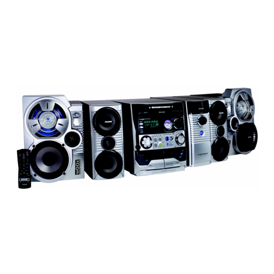
Philips FW-C798 Service Manual Addendum
Power booster
Hide thumbs
Also See for FW-C798:
- Specifications (2 pages) ,
- User manual (32 pages) ,
- User manual (32 pages)
Table of Contents
Advertisement
Quick Links
Service
Service
Service
Service
Service
Service Information
Already published Service Informations :
ADDITION TO SERVICE MANUAL
*Power Booster:
Repair information and selected spare parts are now available for
the Power Booster. For this reason layout, circuit drawing and parts
list are enclosed (Page 1 to 10).
30 - 05 - 2002
Product Service Group CE Audio
FW-C798
A02 - 157
3139 785 30071
Advertisement
Table of Contents

Related Manuals for Philips FW-C798


Summary of Contents for Philips FW-C798
-
Page 1: Service Information
FW-C798 A02 - 157 Service Service Service Service Service Product Service Group CE Audio Service Information Already published Service Informations : ADDITION TO SERVICE MANUAL *Power Booster: Repair information and selected spare parts are now available for the Power Booster. For this reason layout, circuit drawing and parts list are enclosed (Page 1 to 10). -
Page 2: Table Of Contents
Electrical parts list (Main Board) ........9 Electrical parts list (Control Board) ........10 Power Booster Speaker Box Power Booster Speaker Box Power Booster Amplifier Box VERSION VARIATIONS: FW-C798/21 FW-C798/37 FW-V795/21M POWER BOOSTER 3139 118 79650 3139 118 79640 3139 118 79630... -
Page 3: Dismantling Instructions & Service Positions
DISMANTLING INSTRUCTIONS (POWER BOOSTER AMPLIFIER BOX) Dismantling the Front Assembly Service Position A 1. Place the Power Booster Amplifier Box as shown in Picture 1 and Picture 2 and use a screw driver (minus type) to force open the Front assembly. Caution: Do not break the bundle of wires to the front. - Page 4 DISMANTLING INSTRUCTIONS (POWER BOOSTER AMPLIFIER BOX) Dismantling the Rear Assembly Service Position B 1. Remove 4 screws C at the bottom of the Power Booster Note: After repair, be very sure that the cables are tied and Amplifier Box as shown in Picture 4. restored properly to its original position.
-
Page 5: Wiring Diagram
WIRING DIAGRAM - POWER BOOSTER AMPLIFIER BOX (/21/21M VERSION) WIRING DIAGRAM - POWER BOOSTER AMPLIFIER BOX (/37 VERSION) Wiring Diagram (PWB-C798/17) dd wk0212 Wiring Diagram (PWB-C798/01 & PWB-V795/01) dd wk0212... -
Page 6: Component Layout (/21/21M Version)
COMPONENT LAYOUT - POWER BOOSTER AMPLIFIER BOX (/21/21M VERSION) Layout (PWB-C798/01 & PWB-V795/01) dd wk0216... -
Page 7: Component Layout (/37 Version)
COMPONENT LAYOUT - POWER BOOSTER AMPLIFIER BOX (/37 VERSION) Layout (PWB-C798/17) dd wk0217... -
Page 8: Circuit Diagram
CIRCUIT DIAGRAM - POWER BOOSTER AMPLIFIER BOX Note : Some values may varies, see respective parts list for correct value. Circuit Diagram (Power Booster Amp. Box) dd wk0217... -
Page 9: Exploded View & Mechanical Parts List
9965 000 13733 Knob Power 9965 000 13734 Panel Ornamental * for /21/21M version only 9965 000 12992 Badge (PHILIPS) ^ for /37 version only 9965 000 13735 Volume Ring 9965 000 13736 Volume Knob Note : Only the parts mentioned in this list are normal... -
Page 10: Electrical Parts List (Main Board)
ELECTRICAL PARTS LIST - POWER BOOSTER AMPLIFIER BOX (Main Board) MISCELLANEOUS FUSE 9965 000 13777 Fuse 2.5A /21/21M 9965 000 13760 Carbon Film Res 47k 1/8W 5% FUSE 9965 000 13807 Fuse 3.5A 9965 000 13760 Carbon Film Res 47k 1/8W 5% RV431 9965 000 13776 VR14D431K /21/21M... -
Page 11: Electrical Parts List (Control Board)
ELECTRICAL PARTS LIST - POWER BOOSTER AMPLIFIER BOX (Control Board) MISCELLANEOUS 9965 000 13770 Tact Switch 6*6, 4 Pins 9965 000 13744 LED Dia 3mm, Blue VR101 9965 000 13771 VR 100KA*2, 6 Pins CAPACITORS 9965 000 13745 C CAP 0.001uF 50V 20% 9965 000 13746 C CAP 0.1uF 16V 20% 9965 000 13745...