Yamaha BRX-610 Service Manual
Blu-ray disc home theater system; blu-ray disc receiver / speakers
Hide thumbs
Also See for BRX-610:
- Owner's manual (392 pages) ,
- Owner's manual (136 pages) ,
- Owner's manual (225 pages)
Table of Contents
Advertisement
BLU-RAY DISC HOME THEATER SYSTEM
BLU-RAY DISC RECEIVER /
BRX-610 /
The BDX-610 consists of the BRX-610 and NS-PZ20.
The NS-PZ20 consists of the NS-B20, NS-C20 and NS-SWP20.
* When the MAIN P.C.B. is replaced, the serial number and new MAC address MUST be reported to
Yamaha Corporation by e-mail.
For more information, refer to "SERVICE PRECAUTIONS".
This manual has been provided for the use of authorized YAMAHA Retailers and their service personnel.
It has been assumed that basic service procedures inherent to the industry, and more specifi cally YAMAHA Products, are already known
and understood by the users, and have therefore not been restated.
WARNING:
IMPORTANT:
The data provided is believed to be accurate and applicable to the unit(s) indicated on the cover. The research, engineering, and service
departments of YAMAHA are continually striving to improve YAMAHA products. Modifications are, therefore, inevitable and
specifi cations are subject to change without notice or obligation to retrofi t. Should any discrepancy appear to exist, please contact the
distributor's Service Division.
WARNING:
IMPORTANT:
■ CONTENTS
TO SERVICE PERSONNEL ........................................2-4
PREVENTION OF ELECTROSTATIC DISCHARGE ......5
REGION MANAGEMENT INFORMATION .....................6
SYSTEM COMPOSITION ................................................7
FRONT PANELS .............................................................8
REAR PANELS ......................................................... 9-10
REMOTE CONTROL PANELS ..................................... 11
SPECIFICATIONS ................................................... 12-17
INTERNAL VIEW .......................................................... 18
SERVICE PRECAUTIONS ...................................... 19-20
1 0 1 2 3 2
SERVICE MANUAL
E-mail: ycav-keycontrol@gmx.yamaha.com
IMPORTANT NOTICE
Failure to follow appropriate service and safety procedures when servicing this product may result in personal injury,
destruction of expensive components, and failure of the product to perform as specifi ed. For these reasons, we advise
all YAMAHA product owners that any service required should be performed by an authorized YAMAHA Retailer or
the appointed service representative.
The presentation or sale of this manual to any individual or fi rm does not constitute authorization, certifi cation or
recognition of any applicable technical capabilities, or establish a principle-agent relationship of any form.
Static discharges can destroy expensive components. Discharge any static electricity your body may have
accumulated by grounding yourself to the ground buss in the unit (heavy gauge black wires connect to this buss).
Turn the unit OFF during disassembly and part replacement. Recheck all work before you apply power to the unit.
DISASSEMBLY PROCEDURES .............................21-23
REWRITING OPU PARAMETER ............................24-30
SELF-DIAGNOSTIC FUNCTION ............................31-33
BLOCK DIAGRAM ........................................................35
WIRING DIAGRAM .......................................................36
PRINTED CIRCUIT BOARDS .................................37-39
SCHEMATIC DIAGRAMS .......................................40-56
REPLACEMENT PARTS LIST ................................58-60
REMOTE CONTROL ...............................................61-62
SOFTWARE UPGRADE ...............................................63
BDX-610
SPEAKERS
NS-PZ20
P.O.Box 1, Hamamatsu, Japan
'11.12
Advertisement
Table of Contents

Related Manuals for Yamaha BRX-610


Summary of Contents for Yamaha BRX-610
-
Page 1: Table Of Contents
This manual has been provided for the use of authorized YAMAHA Retailers and their service personnel. It has been assumed that basic service procedures inherent to the industry, and more specifi cally YAMAHA Products, are already known and understood by the users, and have therefore not been restated. -
Page 2: System Composition
BRX-610/NS-PZ20 ■ SYSTEM COMPOSITION The BDX-610 consists of the BRX-610 and NS-PZ20. The NS-PZ20 consists of the NS-B20, NS-C20 and NS-SWP20. BDX-610 BRX-610 x 1 NS-PZ20 NS-SWP20 x 1 NS-B20 x 4 NS-C20 x 1... -
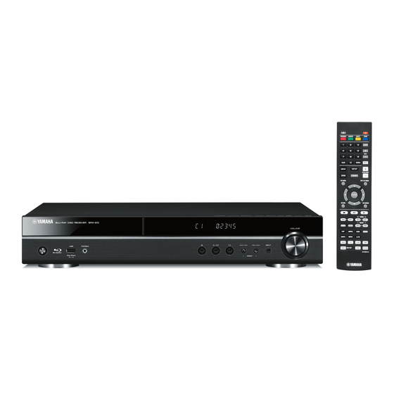
Page 3: Front Panels
BRX-610/NS-PZ20 ■ FRONT PANELS BRX-610 U, C, T, G, F, L models U, C, T, G, F, L models NS-PZ20 NS-B20 NS-C20 NS-SWP20 Front view Side view... -
Page 4: Rear Panels
BRX-610/NS-PZ20 ■ REAR PANELS BRX-610 U, C models T model G model F model L model... - Page 5 BRX-610/NS-PZ20 NS-PZ20 NS-B20 NS-C20 NS-SWP20 U model...
-
Page 6: Remote Control Panels
BRX-610/NS-PZ20 ■ REMOTE CONTROL PANELS 671B92-7 671B92-6 (U, C, T, L models) (G, F models) PROGRAM: Red PROGRAM: Red MARKER: Green MARKER: Green DIGEST: Blue DIGEST: Yellow ZOOM: Yellow ZOOM: Blue... -
Page 7: Specifications
BRX-610/NS-PZ20 ■ SPECIFICATIONS BRX-610 ■ Player Section iPod/iPhone Finish Supported iPod U, C, T, G, F, L models ............ Black color ..................iPod classic Accessories iPod nano (2nd, 3rd, 4th, 5th and 6th generation) Remote control ................x 1 iPod touch (1st, 2nd, 3rd and 4th generation) Battery (R03, AAA, UM-4) .............x 2... - Page 8 BRX-610/NS-PZ20 – “Blu-ray DiscTM” , “Blu-rayTM” , “Blu-ray 3DTM” , “BD-LiveTM” , “BONUSVIEWTM” , and the logos are trademarks of the Blu-ray Disc Association. – HDMI, the HDMI logo and High-Definition Multimedia Interface are trademarks or registered trademarks of HDMI Licensing LLC.
- Page 9 BRX-610/NS-PZ20 NS-PZ20 ■ NS-B20/NS-C20 ■ General Type ....Full-range acoustic suspension speaker system Finish Non-magnetic shielding type U, C, T, G, F, L models ............ Black color Driver Accessory Full-range ........7 cm (2-3/4") cone type x 1 Speaker cable (25 m) ............x 1 Frequency Response Nonskid pad (NS-B20/NS-C20) ..........
- Page 10 BRX-610/NS-PZ20 NS-PZ20 NS-B20 Rear view 115 (4-1/2") 57.5 (2-1/4") Side view ø 5 (1/4") ø 10 (3/8") A screw with a diameter of 5 mm can be used. 88 (3-1/2") [Hole depth: 12 mm (1/2")] NS-C20 Rear view 291 (11-1/2") 150 (5-7/8")
- Page 11 BRX-610/NS-PZ20 • SET MENU TABLE MENU SUB-MENU VALUE General System Screen Saver [On] / Off Auto Power Off Disc/USB/Net: [On] / Off Other Inputs: 1 hour / 2 hours / 4 hours / [8 hours] / Off Setting Disc Auto Playback...
- Page 12 BRX-610/NS-PZ20 MENU SUB-MENU VALUE Display 3D Output [Auto] / Off Setting TV Screen 16:9 Full / [16:9 Normal] / 4:3 Pan Scan / 4:3 Letterbox Video Out Select Composite / [HDMI Auto] / HDMI 1080p / HDMI 1080i / HDMI 720p / HDMI 480p/576p...
-
Page 13: Internal View
BRX-610/NS-PZ20 ■ INTERNAL VIEW MAIN P.C.B. FM TUNER AMP P.C.B. BD MECHANISM UNIT USB P.C.B. OPERATION P.C.B. -
Page 14: Service Precautions
BRX-610/NS-PZ20 ■ SERVICE PRECAUTIONS When the MAIN P.C.B. is replaced, the serial number and new MAC address MUST be reported to Yamaha Corporation by e-mail. (Fig. 1) E-mail: ycav-keycontrol@gmx.yamaha.com ycav-keycontrol@gmx.yamaha.com ycav-ysiss@gmx.yamaha.com Model name BD-S671 Serial number xxxxxxxxx New MAC address... - Page 15 BRX-610/NS-PZ20 Operation Procedure Using the remote control, perform the following procedure while watching the TV monitor screen. With this unit in the standby mode, press the “ ” (On/Standby) key to turn on the power. The initial screen is displayed.
-
Page 16: Disassembly Procedures
BRX-610/NS-PZ20 ■ DISASSEMBLY PROCEDURES (Remove parts in the order as numbered.) Disconnect the power cable from the AC outlet. Removal of Top Cover Removal of BD Mechanism Unit Remove 4 screws ( ① ) and 4 screws ( ② ). (Fig. 1) Remove 4 screws ( ③... - Page 17 BRX-610/NS-PZ20 • How to manually eject the disc tray Disc tray a. Using an Allen hex socket screwdriver (size: 1.3 mm or .050"), move the slider at the bottom side in the direction of the arrow as shown below until the disc tray comes out.
- Page 18 BRX-610/NS-PZ20 Remove the MAIN P.C.B. Removal of Power Supply Unit Remove 3 screws ( ⑤ ), 2 screws ( ⑥ ), screw ( ⑦ ) and Remove 4 screws ( ⑫ ) and 2 screws ( ⑬ ). (Fig. 4) 2 screws ( ⑧...
-
Page 19: Rewriting Opu Parameter
• Test disc set (Part No. WW867900) CD-ROM x 1, DVD-ROM DL x 1, BD-ROM SL x 1, BD-R DL x 1, BD-ROM DL x 1 (Not for service) Items not supplied from Yamaha Corporation • • 2D barcode reader (which supports Data Matrix symbology) •... - Page 20 Note: If you don’t have 2D barcode reader, take a picture of 2D barcode with a digital camera, and send its image data to the following e-mail address. E-mail: ycav-ysiss@gmx.yamaha.com Yamaha Corporation will reply providing the OPU parameter text data. (Fig. 2) E-mail: ycav-ysiss@gmx.yamaha.com Top view of BD mechanism unit ycav-ysiss@gmx.yamaha.com...
- Page 21 BRX-610/NS-PZ20 Writing OPU Parameter and Disc Playback Capability Check <Connection> Disconnect the power cable from the AC outlet and remove the top cover. (See “DISASSEMBLY PROCEDURES”.) Connect the USB port of the PC to the writing port (JP10 on MAIN P.C.B.) of this unit as shown below. (Fig. 3)
- Page 22 BRX-610/NS-PZ20 <Operation> The operation consists of 2 parts as follows. Procedure 1 to 8: Writing OPU Parameter Procedure 9 to 13: Disc Playback Capability Check Press the “ ” (On/standby) key to turn on the power. FL display This unit...
- Page 23 BRX-610/NS-PZ20 Follow the steps below to check that communication between the PC and this unit is established. • Click [TrayOut F1]. The disc tray opens. (Fig. 7) • Click [TrayIn F3]. The disc tray closes. (Fig. 7) If the disc tray does not operate, recheck the connection especially the COM port of the PC and perform operation from the beginning again.
- Page 24 BRX-610/NS-PZ20 Click [Write (F2)] to start writing the OPU parameter. (Fig. 9) When writing of the OPU parameter is completed, the “Pass” indicator lights green. (Fig. 9) Writing being executed Writing completed Rpower8550 5.12.61 (2010/07/15) SONY KEM470 Ver.A −−− ComPort 6 −−−...
- Page 25 BRX-610/NS-PZ20 Press the “ ” (On/standby) key to turn on the power. The FA mode is activated and the screen appears on the TV monitor as shown below. (Fig. 12) TV monitor screen Insert Disc : CD-ROM Current Disc : Current Stage : Press "Stop"...
-
Page 26: Self-Diagnostic Function
BRX-610/NS-PZ20 ■ SELF-DIAGNOSTIC FUNCTION This unit has self-diagnostic functions that are intended for inspection and location of faulty point. ● Starting Self-Diagnostic Function While pressing the “ ” and “ ” keys, connect the power cable to the AC outlet and keep pressing those 2 keys. - Page 27 BRX-610/NS-PZ20 ● Canceling Self-Diagnostic Function Disconnect the power cable from the AC outlet. The self-diagnostic function is cancelled. ● Details of Self-Diagnostic Function 1. FL Display Check 1) Press the “ ”(Play) key on the remote control. (Fig. 3) Check that all segments of the FL display turn on. (Fig. 3) 2) Press the “...
- Page 28 BRX-610/NS-PZ20 3. Protection History Check This menu is used to display the history of protection function. Press the “DISPLAY” key on the remote control and the history of protection function is displayed. (Fig. 5) Numeric values in the figure are given as reference only.
-
Page 29: Block Diagram
BRX-610/NS-PZ20 ■ BLOCK DIAGRAM → → OPERATION SCHEMATIC DIAGRAM SCHEMATIC DIAGRAM OPE1 OPE2 FL12V D3.3V PORTABLE INVERTER U704 U703 U701 /INT_PSW WIRE 3P /INT_PSW FL DRIVER VOL CONTROL GREEN PT6311 EC12E2430803 USB_VCC1 USBP1 JP703 FAUX_L +3.3M 1. /INT_PSW USBM1 A12V D3.3V VP... -
Page 30: Wiring Diagram
BRX-610/NS-PZ20 ■ WIRING DIAGRAM TUNER JP14 JP701 JP704 MAIN JP703 JP18 JP15 JP702 JP13 CON200 CON201 BD Mechanism Unit JP703 JP701 JP702 JP704 OPERATION Front Panel JP703... -
Page 31: Printed Circuit Boards
BRX-610/NS-PZ20 ■ PRINTED CIRCUIT BOARDS FOR INFORMATION ONLY (COMPONENT PARTS NOT AVAILABLE) MAIN MAIN (Side A) (Side B) Tuner (for factory) Writing port (JP704) (JP703) (CON201) (for factory) REMOTE CONTROL OPERATION (JP701) (JP703) DIGITAL COAXIAL/ OPTICAL (JP702) AUDIO IN VIDEO/... - Page 32 BRX-610/NS-PZ20 OPERATION (Side A) Remote control (JP704) sensor MAIN (JP8) VOLUME INPUT PRESET OPERATION (Side B)
- Page 33 BRX-610/NS-PZ20 SPEAKERS SUB- SURROUND CENTER FRONT WOOFER (Side A) (Side B) MAIN (JP9) MAIN (JP1) (CON200) (Side A) (Side B) MAIN (JP15) PORTABLE (standby/on) iPod/iPhone OPERATION (JP703) MAIN (JP13)
-
Page 34: Schematic Diagrams
BRX-610/NS-PZ20 ■ SCHEMATIC DIAGRAMS FOR INFORMATION ONLY (COMPONENT PARTS NOT AVAILABLE) MAIN 1/14 1.15V POWER 33V_OK 33V_OK 4/14 Close to DC-DC RESET# RESET# 9/14 VCC_1.15 BLM21P 10uF/10V/X5R P1_GND BEAD/SMD/0805 C0805/SMD NC0805/SMD 0.1uF/10V 10uF/10V/X5R TDK VLC6045T-2R2N 2.2uH C0805/SMD 0.1uF/10V NC0805/SMD D1.15V Close to DC-DC 2.4K... - Page 35 BRX-610/NS-PZ20 A_DQS1 MAIN 2/14 TEST POINT SMD0.6 D1.5V A_DQS1# TEST POINT SMD0.6 A_DQ3 A_RA0 A_DQ18 A_RA0_2R A_DQ7 A_RA1 A_DQ23 A_RA1_2R AA25 DVCC18_IO_1 A_DQ1 A_RA2 A_DQ19 A_RA2_2R A_DQS0 AE10 DVCC18_IO_1 TEST POINT SMD0.6 AF14 A_DQ6 A_RA3 A_DQ21 A_RA3_2R A_DQS0# TEST POINT SMD0.6...
- Page 36 BRX-610/NS-PZ20 MAIN 3/14 D1.15V B_DQ1 B_RA0 B_DQ19 B_RA0_2R B_DQ0 B_DQ6 B_RA1 B_DQ23 B_RA1_2R DVCC10_K RDQ0_B B_DQ1 B_DQ0 B_RA2 B_DQ16 B_RA2_2R DVCC10_K RDQ1_B B_DQ2 B_DQ7 B_RA3 B_DQ21 B_RA3_2R DVCC10_K RDQ2_B B_DQ3 B_DQ3 B_RA4 B_DQ17 B_RA4_2R DVCC10_K RDQ3_B B_DQ4 B_DQ5 B_RA5 B_DQ22...
- Page 37 BRX-610/NS-PZ20 HW TRAPPING D3.3V NAND NFWEN NFWEN 9/14 MAIN 4/14 D3.3V NFREN NFREN 9/14 DVCC33_IO_5 STXN FLASH DVCC33_IO_5 STXP NFCEN DVCC33_IO_2 NFCEN 9/14 NFCEN2 R0603/SMD NFCEN2 9/14 DVCC33_IO_2 SRXP C120 C121 NFD7 DVCC33_IO_3 SRXN I/O7 0.1uF/6.3V/X7R 4.7uF/6.3V/X5R NFD6 NFRBN2 NFCLE...
- Page 38 BRX-610/NS-PZ20 MAIN 5/14 HDMI TX AVDD33_VDAC_R AOMCLK IC VIDEO MODULE POWER C AVDD33_VDAC_R AOMCLK AOBCK close to connector AVSS33_VDAC_R AOBCK PORT AOLRCK TMDS differential impedance 100 OHM AOLRCK AVDD33_VDAC_X AOSDATA0 MTK suggest W/S/GS=5/7/20 D3.3V RClamp0524J/NC AVDD33_VDAC_X AOSDATA0 AOSDATA1 TX2+ F_TX2+...
- Page 39 BRX-610/NS-PZ20 MAIN 6/14 AUDIO D1.15V R150 R150 AVDD12_HDMI_RX VDINHSYNC PCM_DSD# TP66 TEST POINT SMD1.0 VDD12_HDMI_RX VDINHSYNC PCM_DSD# 8/14 VDINVSYNC AUDIO_RESET# TP67 TEST POINT SMD1.0 AUDIO_RESET# 8/14 VDD12_HDMI_RX VDINVSYNC VDINCLK TEST POINT SMD1.0 TP68 VDINCLK C186 C187 HDMI RX 4.7uF/6.3V/X5R R151...
- Page 40 BRX-610/NS-PZ20 MAIN 7/14 HDMI RX RXC- HDMI_RXC- 6/14 RXC+ HDMI_RXC+ 6/14 RClamp0524J/NC RClamp0524J/NC RX2+ RX2+ RX0+ RX0+ RX2- HDMI_RX2- 6/14 RX2- RX2- RX0- RX0- RX2+ HDMI_RX2+ 6/14 RX1+ RX1+ RXC+ RXC+ RX1- HDMI HDMI_RX1- 6/14 RX1- RX1- RXC- RXC- RX1+...
- Page 41 BRX-610/NS-PZ20 MAIN 8/14 AUDIO CNT AMUTE AMUTE 5/14, 9/14 AUDIO_RESET# AUDIO_RESET# 6/14 PCM_DSD# PCM_DSD# 6/14 4/14 4/14 SDTO_CSW R206 AOSDATA2 AUDIO I2S SDTO_SLR R207 AOSDATA1 SDTO_FLR R208 AOSDATA0 AOMCLK AOMCLK 5/14 LRCK R209 AOLRCK AOLRCK AOLRCK 5/14, 9/14 R210 AOBCK...
- Page 42 BRX-610/NS-PZ20 MAIN 9/14 D3.3V DVCC33_IO_STB R226 GPIO8_VOUTCLK1 NAND_WP# R227 PWR5V0_RX NAND_WP# DVCC33_IO_STB GPIO8 TP101 NAND_WP# 4/14 standby DVCC33_IO_STB C220 ETCOL_VOUTD15 R228 LIN_SDATA ETTXEN: HW TRAPPING ETCOL power 0.1uF/6.3V/X7R ETCRS_VOUTD2 R229 R229 HTPLG0_RX TP102 H*default, RSTI as BE ETCRS domain ETMDC_VOUTVSYNC...
- Page 43 BRX-610/NS-PZ20 MAIN 10/14 FE_1.15V D1.15V NC11 NC20/SMD MISC V14REF V14REF C231 C232 C233 C234 C235 V14REF AVDD12_1A V14REF 11/14 close to IC 0.1uF/6.3V/X7R 0.1uF/6.3V/X7R 4.7uF/6.3V/X5R 10uF/6.3V/X5R 0.1uF/6.3V/X7R AVDD12_2A C237 CD_VR FVREF C0402/SMD C0402/SMD C0603/SMD C0805/SMD C0402/SMD FVREF 4.7uF/6.3V/X5R FEGIO4 AGND12_2A...
- Page 44 BRX-610/NS-PZ20 MAIN 11/14 10/14 M12V M12V 10/14 V14REF 10/14 MVCC C263 0.1uF/25V/Y5V C19V SLED2_N 10/14 C267 TILT+ SLED2_P TILT+ 10/14 FB15 BLM21P Close to 1405 pin26 Close to TPC1391 pin14 0.1uF/25V/Y5V TILT- P12V_3 TILT- 10/14 V14REF BEAD/SMD/0805 C268 C271 C264...
- Page 45 BRX-610/NS-PZ20 TUNER TUN_SCL Q702 2SD1664DAQ TUN_SCL 14/14 MAIN 12/14 TUN_SDA TUN_SDA 14/14 D12V TUN_RST TUN_RST 14/14 TUN_GP C446 TUN_GP 14/14 D1.15V +3.3M +3.3M FB64 BLM21P(0805) R410 PSU_T_DET/P_CON2 100uF/16V R465 +3.3M D12V 47K_1%_NC FB17 BLM21P RS232 TO BD R429 MTK_RXD C370...
- Page 46 BRX-610/NS-PZ20 MAIN 13/14 EXT_REM EXT_REM 12/14 +3.3M IPOD USB_SEL +3.3M USB_SEL 12/14 CK35 USB_N_OE USB_N_OE 12/14 IPOD_UPDA IPOD_UPDA 12/14 IR_IN R516 IPOD_IN IPOD_IN 12/14 IPOD_N_RST 4.7K IPOD_N_RST 12/14 IPOD_IF IPOD_IF 12/14 IPOD_RX IPOD_RX 12/14 R517 EXT_REM IPOD_TX IPOD_TX 12/14 REMOTE...
- Page 47 BRX-610/NS-PZ20 OUTPUT AUDIO IN SUBWOOFER/ MAIN 14/14 VIDEO TUNER TUN_SCL 12/14 TUN_SCL TUN_SDA 12/14 TUN_SDA Stacked RCA TUN_RST 12/14 TUN_RST Tuner TUN_GP 12/14 TUN_GP R563 SW_PREOUT RAUX_IN_R AUDIO SEL JP14 AU_SEL1 12/14 AU_SEL1 CVBS AU_SEL2 12/14 AU_SEL2 TUN_RST RAUX_IN_L TUN_SDA...
- Page 48 BRX-610/NS-PZ20 OPERATION +3.3M D3.3V VFD DISPLY R714 U702 VFD25-1123 R727 R728 C700 C707 0.1UF CAPACITOR POL Remote FB23 BLM21P(0805) C710 1000P R729 10 VOL_RA control U703 C711 1000P R730 10 sensor JP701 VOL_RB IR IR FB35 BLM21P FB36 BLM21P D3.3V...
- Page 49 BRX-610/NS-PZ20 R702 + CE702 C702 470uF/50V C703 C704 D12V Q702 C706 C707 JP701 0.1u/50V 0.1u/50V 0.1u/50V 2SD1644DAQ Remarks: 7.5V 7.5V 7.5V 7.5V to FAN C705 ECQV : Pansanic ECQV Type Q703 D3.3V Film type for sound quality 2SD1644DAQ_NC CE701 C701 Q701 CON3 DIP2.0...
- Page 50 BRX-610/NS-PZ20 Page 53 R754 0_NC to MAIN_JP15 AGND C734 U706B C736 10p(CH) R742 C730 10uF/16V AUX_L MMZ1608Y601 10uF/16V MMZ1608Y601 C726 R744 R746 NJM3404AM-TE1 JP703 100p_NC C728 100K 470p(SL) R750 AUX_R P12V_OP 100K AUX_L VREF Portable IN CONN SOCKET 3 PORTABLE...
- Page 51 BRX-610/NS-PZ20 MEMO MEMO...
-
Page 52: Replacement Parts List
BRX-610/NS-PZ20 BRX-610 ■ REPLACEMENT PARTS LIST ● OVERALL ASSEMBLY... - Page 53 BRX-610/NS-PZ20 WARNING • Components having special characteristics are marked and must be replaced with parts having specifications equal to those originally installed. Ref No. Part No. Description Remarks Markets Ref No. Part No. Description Remarks Markets ZA995500 P.C.B. ASSEMBLY JEP610U-R0...
- Page 54 BRX-610/NS-PZ20 NS-PZ20 ● OVERALL ASSEMBLY Ref No. Part No. Description Remarks Markets WZ118300 CABINET ASSEMBLY YA897A00 DRIVER WOOFER 16cm 6Ω WY603300 FRONT GRILLE ASSEMBLY WY587000 TERMINAL ASSEMBLY 2P, PUSH TYPE WY263600 FRONT PANEL WW479900 PACKING 15x175 WU037000 PACKING 3x550 WE955200 BIND HEAD TAPPING SCREW...
-
Page 55: Remote Control
BRX-610/NS-PZ20 ■ REMOTE CONTROL ● 671B92-7 (U, C, T, L models) / 671B92-6 (G, F models) SCHEMATIC DIAGRAM PANELS 671B92-7 671B92-6 (U, C, T, L models) (G, F models) OSCI OSCO 47uF/50V IROUT POWER PROGRAM: Red PROGRAM: Red MARKER: Green... - Page 56 BRX-610/NS-PZ20 KEY NO. LAYOUT KEY NO. LAYOUT Key No. Key Name custom code data code 0 data code 1 Key No. Key Name custom code data code 0 data code 1 (Open/Close) POP-UP/MENU (Standby/On) (Left) PROGRAM (Red) ENTER MARKER (Green)
-
Page 57: Software Upgrade
BRX-610/NS-PZ20 ■ SOFTWARE UPGRADE...