Table of Contents
Advertisement
Quick Links
Advertisement
Table of Contents

Related Manuals for Barco F80-Q7


Summary of Contents for Barco F80-Q7
- Page 1 F80 series User Manual R5906852/00 21/09/2017...
- Page 2 Registered address: Barco NV President Kennedypark 35, 8500 Kortrijk, Belgium Phone: +32 56.23.32.11 Fax: +32 56.26.22.62 Support: www.barco.com/en/support Visit us at the web: www.barco.com Barco Fredrikstad AS Habornveien 53, N-1630 Gamle Fredrikstad, Norway Phone: +47 6930 4550 Fax: +47 6930 4580 Support: Support.fre@barco.com...
- Page 3 The period of guarantee begins on the date of transfer of risks, in the case of special systems and software on the date of commissioning, at latest 30 days after the transfer of risks. In the event of justified notice of complaint, Barco can repair the fault or provide a replacement at its own discretion within an appropriate period.
-
Page 5: Table Of Contents
Table of contents TABLE OF CONTENTS 1. Safety ....................... . 3 General considerations. - Page 6 Specifications of the F80-Q7 ........
-
Page 7: Safety
F80 projector. Clarification of the term “F80” used in this document When referring in this document to the term “F80” means that the content is applicable for following Barco products: •... -
Page 8: Important Safety Instructions
VOLTAGE ELECTRIC and ELECTRONIC CIRCUITRY and HIGH BRIGHTNESS PROJECTORS) in performing a task, and of mea- sures to minimize the potential risk to themselves or other persons. Only Barco authorized SERVICE PERSONNEL, knowledgeable of such risks, are allowed to perform service functions inside the product enclosure. The term USER and OPERATOR refers to any person other than SERVICE PERSONNEL. - Page 9 Never expose the projector to rain or moisture. In the event of fire, use sand, CO or dry powder fire extinguishers. Never use water on an electrical fire. Always have service performed on this projector by authorized Barco service personnel. Always insist on genuine Barco replacement parts. Never use non-Barco replacement parts as they may degrade the safety of this projector.
- Page 10 • Remove all power from the projector and refer servicing to Barco authorized repair center under the following conditions: When the power cord or plug is damaged or frayed.
-
Page 11: Product Safety Labels
Caution! Do not stare into beam, RG2 product. Hazard RG3: not for household use symbol. Hazard RG3: optical radiation warning symbol. For F80-Q7, F80-4K7: For North America: THIS PRODUCT IS IN CONFORMITY WITH PERFORMANCE STANDARDS FOR LASER PRODUCTS UNDER 21 CFR 1040, EXCEPT WITH RESPECT TO THOSE CHARACTERISTICS AUTHORIZED BY VARIANCE NUMBER 2017-V-4837 EFFECTIVE September 13, 2017. -
Page 12: Risk Group 3 Safety
Do not open or disassemble the projector as this may cause damage by the exposure of laser radiation. FOR PROFESSIONAL USE ONLY means installation can only be carried out by Barco AUTHORIZED PERSONNEL familiar with potential hazards associated with high intensity light beams. - Page 13 1. Safety Restriction Zone (RZ) based on the HD The HD depends on the amount of lumens produced by the projector and the type of lens installed. See next chapter"HD in function of the lens Throw Ratio (TR)", page 11. To protect untrained end users (as cinema visitors) the installation shall comply with the following installation requirements: Opera- tors shall control access to the beam within the hazard distance or install the product at the height that will prevent spectators’...
-
Page 14: Hd For Fully Enclosed Projection Systems
1. Safety RESTRICTED AREA Image 1-2 1.4.3 HD for fully enclosed projection systems Hazard Distance (HD) is the distance measured from the projection lens at which the intensity or the energy per surface unit becomes lower than the applicable exposure limit on the cornea or on the skin. The light beam is considered (to be) unsafe for exposure if the distance from a person to the light source is less than the HD. -
Page 15: Hd In Function Of The Lens Throw Ratio (Tr)
HD in function of the lens Throw Ratio (TR) TR (Throw Ratio) The ratio of the distance to the screen (throw) to the screen width. HD versus Throw Ratio F80-Q7, F80-4K7 F80-Ultra, F80-Q9, F80-4K9 Throw Ra o Image 1-4 Graph shows Hazard Distance in meters versus Throw ratio of the lens... - Page 16 1. Safety R5906852 F80 SERIES 21/09/2017...
-
Page 17: Remote Control Unit
2. Remote Control Unit 2. REMOTE CONTROL UNIT Remote control, Battery installation Where to find the batteries for the remote control ? The batteries are not placed in the remote control unit to avoid control operation in its package, resulting in a shorter battery life time. -
Page 18: Using The Xlr Connector Of The Rcu
2. Remote Control Unit AUTION Replace with the correct battery type. Use two AA size batteries. There is a risk of explosion if the battery is replaced with an incorrect type. AUTION Replace the battery as explained above. There is a risk of explosion if the battery is incorrectly installed. - Page 19 2. Remote Control Unit Image 2-5 R5906852 F80 SERIES 21/09/2017...
- Page 20 2. Remote Control Unit R5906852 F80 SERIES 21/09/2017...
-
Page 21: Input & Communication
3. Input & Communication 3. INPUT & COMMUNICATION Overview • Introduction • Connection Panel • Making connections • Connector specifications • Control interfaces • LED and Button indication chart Introduction General The Input & Communication features of the projector consists of a local keypad and a communication panel situated at the left side, and a connection panel (sources and control connections) located at the back side. -
Page 22: Making Connections
3. Input & Communication Nb. Name Description Purpose Mini jack 3,5mm connector for wired For Projector Control remote USB 2.0 type A, 4 pin( 2x Rear and For Software upgrade 1x Front) Standard RJ45 connector For Projector Control For Projector Input Standard display port DL-DVI-D For Projector Input. -
Page 23: Display Port 1.2
3. Input & Communication Parameter Value Max. pixel rate 330 MHz (dual link), 165 Mhz (single link) Progressive Scan format Max. input data resolution 1920x1200 60Hz (Single link), 2560x1600 60Hz (Dual Link).1920x2400 @60Hz Bit depth 8 bit EDID Supported HDCP Supported 3.4.2 Display Port 1.2... -
Page 24: Hdbase T
3. Input & Communication Parameter Value Connectors 1x) BNC 75 ohm type IEC 60169-8, Amendment 2 1997, A Bandwidth >3 GHz Return loss >10dB at 3GHz Impedance 75 ohm resistive 3.4.5 HDBase T Specifications Parameter Value Reference specification HDBaseT 1.0 Specification, June 2010 Connector Standard RJ-45, 8P8C Signal characteristics... -
Page 25: Lan/Ethernet
3. Input & Communication 3.5.2 LAN/Ethernet Specifications Parameter Value Ethernet connector 1 RJ45 Connector for projector control (not content) Protocols DHCP, TCP/IP, UDP/P Speed 10/100 Mbit/1000Mbit 3.5.3 USB-A port Specifications Parameter Value USB connector Type A Function Firmware upgrade using USB sticks Power Power 5V, max 1,5A (out) Standard... - Page 26 3. Input & Communication R5906852 F80 SERIES 21/09/2017...
-
Page 27: Getting Started
4. Getting Started 4. GETTING STARTED About this chapter This chapter describes how to power up, control and set up your projector setup when the physical installation process is complete. How controlling the projector ? The projector can be controlled by the local keypad, by the remote control unit or by browser application. Location of the local keypad ? The local keypad is located on the right side of the projector. -
Page 28: Power Modes
4. Getting Started The keys are equipped with white and blue backlit LEDs. Power button is equipped with white, blue and red backlit. The LEDs are controlled according to the features available. Remote Control Unit buttons Backspace (while entering Button pressed indicator. values) XLR connector. -
Page 29: Power Mode Transitions
4. Getting Started Mode Description ON (normal) Projector is booted up and the light source is on READY Projector is booted up but the light source is off ECO (Standby) Light source is switched off and projector electronics are powered down Energy consumption is significantly lowers in ECO (Standby) mode: only <0.5W if network is not plugged in and 2W with network (WakeOnLan). -
Page 30: Going From Ready To On
4. Getting Started The background image of the startup screen and info screens can be changed with Projector Toolset with an installed F80 plug-in. Description Plug the 3-prong plug of power cord into a grounded AC outlet. The projector will go to READY mode. During this stage the system boots and performs the internal check of the boards. -
Page 31: Power Off Projector
Never switch off the projector by means of unplugging mains cord or by cut down of mains power. Barco advises to keep the projector always powered and use the ECO mode for low power consumption. How to unplug the projector 1. -
Page 32: Using The Rcu
4. Getting Started Important rules If using the projector 24 h/day, please adhere to the following rules: • Make sure to temporary switch off the projector during 2 minutes at least once per 12 hours. The power down action will automatically and invisibly trigger a grey test pattern running within the projector. -
Page 33: Projector Address
4. Getting Started 45° 45° Image 4-5 RCU to one of the IR sensors Projector Address Projector address Address installed in the projector to be individually controlled. Broadcast address Projector will always execute the command coming from a RCU programmed with that broadcast address. 4.8.1 Controlling the projector Why a projector address? -
Page 34: Displaying And Programming Addresses Into The Rcu
4. Getting Started 4.8.2 Displaying and Programming addresses into the RCU Displaying the Projector Address on the Screen. 1. Press the Address button to see the projector address (proximately 2 seconds). The projector’s address is displayed on the LCD status screen. How to Program an Address into the RCU? 1. - Page 35 4. Getting Started Quick test pattern selection 1. Press the Test pattern button on the remote control or local keypad. Image 4-8 A first test pattern will be displayed. 2. Press as may times on that button until the desired pattern is displayed R5906852 F80 SERIES 21/09/2017...
- Page 36 4. Getting Started R5906852 F80 SERIES 21/09/2017...
-
Page 37: Graphic User Interface (Gui)
5. Graphic User Interface (GUI) 5. GRAPHIC USER INTERFACE (GUI) Overview • Overview • Navigation • Test Patterns Overview GUI - Main Menu overview The projector on screen display (OSD) is the primary user interface (UI). From here, you can review and adjust all projector and display settings. -
Page 38: Test Patterns
5. Graphic User Interface (GUI) To start up the menu structure, press MENU (1). Use the arrow keys (Menu Navigation buttons) to navigate to the desired menu item (2). The background color changes to light blue. Press the Menu Selection button (center key of the arrow keys), also called OK button, to activate that item and to jump one level deeper (3). - Page 39 5. Graphic User Interface (GUI) Push the Test Patterns button on the RC or on the local keypad. Image 5-4 Main menu, Test Patterns 2. In the Test Patterns menu, select either Patterns, Internal, or P7 Calibration test patterns. 3. In the chosen submenu, select the desired test pattern from the list. You can select one of the following Patterns test patterns: Refresh Native Black...
- Page 40 5. Graphic User Interface (GUI) R5906852 F80 SERIES 21/09/2017...
-
Page 41: Gui - Source
6. GUI – Source 6. GUI – SOURCE About the Source menu This menu is used to select, review and configure sources into the projector. Overview of features • Source Selection • Connector Settings Source Selection How to select? 1. Press Menu to activate the menus and select Source. Image 6-1 Select Source 2. - Page 42 6. GUI – Source The Connector Settings menu for this connector will be displayed. All default values are Auto. Image 6-4 5. To apply a limit on the used color space, select one of the other values in Color space. 6.
-
Page 43: Gui - Image
7. GUI – Image 7. GUI – IMAGE Overview of features • Setting image levels manually • P7 Realcolor • HDR – Perceptual Quantizer (PQ) Setting image levels manually Purpose Contrast: Change the contrast of the complete output signal (main and PiP window together) of the projected image. Brightness: Change the brightness of the complete output signal (main and PiP window together) of the projected image. -
Page 44: P7 Realcolor
7. GUI – Image Image 7-4 Brightness slider 3. Use the ▲ or ▼ key to select Contrast or Saturation. go to Home - Image and select Contrast or Saturation. How to set up Saturation Level 1. In the main menu, select Image → Saturation. Image 7-5 Image menu —... -
Page 45: Hdr - Perceptual Quantizer (Pq)
7. GUI – Image Image 7-7 Advanced menu — P7 Realcolor The P7 menu is displayed. Image 7-8 P7 Realcolor menu 2. Select the desired Mode. Choose one of the following: Native: Default mode, with default values. All other options in the P7 menu are disabled. Custom RGB: 3–point color configuration. - Page 46 7. GUI – Image Image 7-9 The PQ menu is displayed Image 7-10 2. Select the desired Unit (nits or foot-lambert). 3. Enter the Screen luminance (either in nit, or foot-lambert). R5906852 F80 SERIES 21/09/2017...
-
Page 47: Gui - Installation
8. GUI – Installation 8. GUI – INSTALLATION Overview of features • Configuring the lens, shift • Orientation • Warping • Blending • Laser illumination • Active 3D Set up Configuring the lens, shift What can be done? The image can be shifted by using the vertical and horizontal lens shift. Lens shift is only possible when lens shift is calibrated. -
Page 48: Warping
8. GUI – Installation The following installation are possible: • front/table • front/ceiling • rear/table • rear/ceiling How to set the correct orientation 1. In the main menu, select Installation → Orientation. Image 8-3 Installation menu, Orientation The Orientation menu is displayed. Image 8-4 Orientation menu 2. -
Page 49: Warping - Screen Size
8. GUI – Installation Image 8-5 2. In the Warp menu, click Warp to toggle between On and Off. Image 8-7 Image 8-6 8.3.3 Warping – Screen Size About (Warp) Screen Size adjustment If the used source aspect ratio is different than the projector aspect ratio, e.g. source is 16:9 and projector is 16:10, then black bars will be projected. -
Page 50: Warping - 4 Corners Adjustment
8. GUI – Installation Image 8-9 Warp Menu, Screen Size The Screen Size menu is displayed. Image 8-10 Screen size 2. Select either Screen width or Screen height. 3. Set the new value to shrink either the width or height of the warp outline so that the outline is equal with the active source. Tip: A red border will be projected along with the current image. -
Page 51: Warping - Bow
8. GUI – Installation Image 8-12 Warp menu, 4 Corners The 4 Corners menu is displayed. Image 8-13 4 Corners Warping 2. To enable 4 Corners warping, make sure the 4 corners slider is set to On. The slider is enabled when set to the right and when it is colored blue. 3. -
Page 52: How To Adjust
8. GUI – Installation Image 8-14 Bow distortion How to adjust 1. In the main menu, select Installation → Warp. Image 8-15 Installation menu, Warp 2. In the Warp menu, select Bow. Image 8-16 Warp menu, Bow A check symbol at the bottom right corner indicates that the bow function is activated. 3. -
Page 53: Warping - Warp Files
8. GUI – Installation Image 8-17 Bow adjustment 4. To enable a symmetric adjustment, make sure the Symmetric slider is set to On. The slider is enabled when set to the right and when it is colored blue. 5. Select an adjustment point and use the arrow keys to adjust. When selecting a mid point of an edge, the bow angle can be adjusted. -
Page 54: Blending
8. GUI – Installation The Warp Files menu is displayed. Image 8-20 3. If any custom Warp files are available, select the desired warp file. Image 8-21 4. Click on the on/off button on top to activate the selected warp file. Image 8-22 Blending About Blending... -
Page 55: Blend Zones
8. GUI – Installation 8.4.1 Blend Zones About offset and blending width or height Offset is used to clip the image. The larger the offset value, the more the image is masked (by black bar) at the corresponding side. E.g. Top offset of 100 will blank the top 100 lines. Height or width is used to create a blending zone with a smooth brightness drop off. - Page 56 8. GUI – Installation Image 8-25 Start position (offset) Blending width 5. First select an offset and click Menu selection to activate the selection. Use the arrow keys to change the value (the start position of the blending) Repeat for the other edges if necessary. 6.
-
Page 57: Black Level Adjustment
8. GUI – Installation Image 8-26 Set up for projector 1 Image 8-27 Set up for projector 2 8.4.2 Black level adjustment About adjusting the black level The purpose of the black level adjustment is to align the black levels in the overlapped regions with the black levels in the other regions. -
Page 58: Black Level Files
8. GUI – Installation Image 8-28 Installation menu, Blend 2. In the Blend menu, select Black Level. Image 8-29 Blend menu — Black level The Black Level menu is displayed. Image 8-30 Black Level menu 3. To manually change the black levels, disable the Automatic slider on top of the menu. 4. -
Page 59: Blend Files
8. GUI – Installation Image 8-31 Installation menu, Blend 2. In the Blend menu, select Black Level Files. Image 8-32 Blend menu, Black Level Files The Black Level Files menu is displayed. Image 8-33 3. If any custom Black Level adjustment files are available, select the desired file. Image 8-34 4. - Page 60 8. GUI – Installation For more information on uploading/downloading Blend files using curl or other tools that supports HTTP upload, refer to the Pulse API Reference Guide. How to activate an uploaded Blend configuration file? 1. In the main menu, select Installation → Blend. Image 8-35 Installation menu, Blend 2.
-
Page 61: Laser Illumination
8. GUI – Installation Laser illumination What can be done? Within a certain power mode, the light output of the laser can be reduced by reducing the laser power. How to reduce the power 1. In the main menu, select Installation → Illumination → Power. Image 8-39 Illumination menu, Power The actual power setting is indicated at the bottom of the Power button. - Page 62 8. GUI – Installation 2. Select the desired the stereo Dark Time. 3. Use the slider to set the desired stereo sync delay. 4. If necessary to invert the stereo sync, click the Swap Eye option. R5906852 F80 SERIES 21/09/2017...
-
Page 63: Gui - System Settings
9. GUI – System Settings 9. GUI – SYSTEM SETTINGS Overview of features • Communication • Themes • Standby ECO • Service Menu • Reset Communication About a network connection Network connection is required to communicate with the projector via LAN or Internet. The setup could be done manually (set address, subnet mask and default gateway according to network specification), or automatically assign (DHCP). -
Page 64: Wired Ip Address Set Up
9. GUI – System Settings 9.1.2 Wired IP address set up How to automatically set up the IP address 1. In the main menu, select System Settings → Communication → LAN. Image 9-1 Communication menu, LAN The LAN menu is displayed Image 9-2 LAN menu 2. -
Page 65: Themes
9. GUI – System Settings 2. Disable Automatic. Put the switch to the left. The switch becomes gray. 3. Use the ▲ or ▼ key to select Address and press OK button to activate the input box. 4. Use the ▲ or ▼ key to change the selected character. Use the ◄... -
Page 66: Service Menu
9. GUI – System Settings Image 9-7 2. To disable the ECO mode, make sure the Bow slider is set to Off. The slider is disabled when set to the left and when it becomes grey. Service Menu About the service menu The service menu can only be entered with a Service code. -
Page 67: Service - Color
9. GUI – System Settings 3. In the Service menu, select Color Wheel. Image 9-10 The Color Wheel menu will be displayed. Image 9-11 4. Change the values to the desired position. 9.4.2 Service – Color AUTION The native colors have been measured and set during factory production. Do not change them, unless parts of the optical path have been replaced due to servicing. -
Page 68: Service - Statistics
9. GUI – System Settings The Color menu will be displayed. Image 9-14 4. Select the desired value to change and confirm. 5. Change the values to the desired position, taking into account the color gamut values. 6. Select APPLY and click OK. 9.4.3 Service –... -
Page 69: Lens Calibration
9. GUI – System Settings The Statistics will be displayed. Image 9-17 9.4.4 Lens Calibration Lens calibration is a time consuming operation. How to calibrate 1. In the main menu, System Settings → Service. Image 9-18 2. Enter the service code. 3. -
Page 70: Lens Features
9. GUI – System Settings Horizontal shift Vertical shift Focus Zoom The text Calibration in progress will be displayed next to selected function until the calibration is completed. When an error is detected, the message Calibration Error is displayed next to function. 9.4.5 Lens features What can be done? -
Page 71: Service - Pixel Shift
9. GUI – System Settings 9.4.6 Service – Pixel Shift About Pixel Shift This setting allows production to fine tune the wobulator/XPR until the marker is in the ‘bullseye’. During the settings, the repetitive on screen pattern ‘CROSS HATCH’ must be displayed. The maintenance person has to align the both following images with the sliders available in this menu. - Page 72 9. GUI – System Settings Setting Default value ImageConnector Color Space auto auto Signal Range ImageSource Source files Standard ImageFeatures Contrast mid value Brightness mid value Saturation mid value Cropping Aspect Ratio 16:9 ImageRealColor P7 Realcolor all set to native ImageWarp Screen size 5120x3200 / 2560x1600...
- Page 73 9. GUI – System Settings The Reset menu is displayed. Image 9-29 Reset menu 2. Navigate to the checkbox next to the settings that need to be reset and press OK. Multiple selection are possible. 3. Select RESET and press OK to reset all selected settings. R5906852 F80 SERIES 21/09/2017...
- Page 74 9. GUI – System Settings R5906852 F80 SERIES 21/09/2017...
-
Page 75: Status Menu
10. Status menu 10. STATUS MENU This is a status menu only. No changes can be made to settings from this menu. Overview • Status menu overview 10.1 Status menu overview Status menu While in the main menu, press Status. Source status Displays active source information Product... - Page 76 10. Status menu R5906852 F80 SERIES 21/09/2017...
-
Page 77: Maintenance
11. Maintenance 11. MAINTENANCE About this chapter This chapter contains general maintenance procedures. Overview • Cleaning the lens • Cleaning the exterior of the projector • Filters 11.1 Cleaning the lens To minimize the possibility of damage to optical coatings, or scratches to lens surfaces follow the cleaning procedure as described here precisely. - Page 78 11. Maintenance R5906852 F80 SERIES 21/09/2017...
-
Page 79: Specifications
A. Specifications A. SPECIFICATIONS A.1 Specifications of the F80-Q7 Overview Projector type Single-chip DLP projector Technology 0.64" DMD Resolution 2,560 x 1,600 (WQXGA) native Input resolutions 4,096 x 2,400 max. Output Resolutions 2,560 x 1,600 (WQXGA) Brightness 7,000 lumens Contrast ratio... -
Page 80: Specifications Of The F80-4K7
A. Specifications Orientation 360° rotation, no restrictions Inputs HDMI, DVI, HDBaseT, DisplayPort, SDI, DMX Power requirements 100-240V / 50-60Hz Power consumption 950 W nominal, 1,100 W maximum Noise level (typical at 25°C/77°F) 35 dB(A) Dimensions (WxLxH) 480 x 680 x 227 mm / 18.9 x 26.7 x 8.9 in Weight 25.5 kg / 56.2 lbs Certifications... -
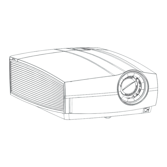
Page 81: Dimensions Of A F80
A. Specifications Brightness 9,000 lumens Contrast ratio 1,300:1 Aspect ratio 16:10 Optical lens shift Motorized zoom, focus, vertical and horizontal shift Throw Ratio 0.85 - 1.06 ; 1.06 - 1.43 ; 1.43 - 2.12 ; 2.12 - 3.18 and compatible with FLD/FLD+ series (with adapter) Light source Laser phosphor Light source lifetime... -
Page 82: Technical Regulations
A. Specifications A.6 Technical Regulations Certificates Image A-5 Nemco mark 60950 Image A-3 Image A-4 Image A-2 Image A-6 Rohs CE mark EAC mark CCC mark Image A-7 Image A-8 FCC label RCM mark R5906852 F80 SERIES 21/09/2017... -
Page 83: Environmental Information
(Also called RoHS of Chinese Mainland), the table below lists the names and contents of toxic and/or hazardous substances that Barco’s product may contain. The RoHS of Chinese Mainland is included in the MCV standard of the Ministry of Information Industry of China, in the section “Limit Requirements of toxic substances in Electronic Information Products”. -
Page 84: Taiwan Rohs Compliance
Chinese Mainland, marked with the Environmental Friendly Use Period (EFUP) logo. The number inside the EFUP logo that Barco uses (please refer to the photo) is based on the “General guidelines of environment-friendly use period of electronic information products” of Chinese Mainland. -
Page 85: Turkey Rohs Compliance
Barco contact information Registered office address: President Kennedypark 35, 8500 Kortrijk, Belgium Contact address: Beneluxpark 21, 8500 Kortrijk, Belgium Contact address (for Taiwan) : Barco ltd.., 33F., No. 16. Xinzhan Rd., Banqiao Dist.,, New Taipei City 220, Taiwan R5906852 F80 SERIES 21/09/2017... -
Page 86: Product Info (Taiwan)
Tel: +886-2-7715-0099, Fax: +886-2-7715-0097 E-mail: service.taiwan@barco.com Importers contact information To find your local importer, contact Barco directly or one of Barco’s regional offices via the contact information given on Barco’s web site, www.barco.com. Made in information The made in country is indicated on the product ID label on the product itself.