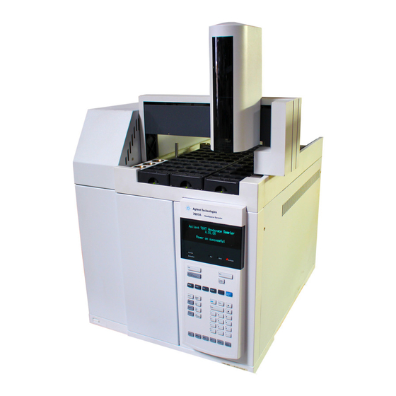
Agilent Technologies 7697A Maintenance Manual
Headspace sampler
Hide thumbs
Also See for 7697A:
- Troubleshooting manual (92 pages) ,
- Advanced operation manual (90 pages) ,
- Operation manual (88 pages)
Table of Contents
Advertisement
Quick Links
Advertisement
Table of Contents

Related Manuals for Agilent Technologies 7697A


Summary of Contents for Agilent Technologies 7697A
- Page 1 Agilent 7697A Headspace Sampler Maintenance Agilent Technologies...
- Page 2 A CAUTION notice denotes a hazard. It prior agreement and written consent from permitted by applicable law, Agilent calls attention to an operating Agilent Technologies, Inc. as governed by disclaims all warranties, either express procedure, practice, or the like that, if United States and international copyright...
-
Page 3: Table Of Contents
Contents About Maintaining the Headspace Sampler Overview of Maintenance Where to find a procedure Early Maintenance Feedback feature Tools and Materials Required for Maintenance Safety Removing Covers and Components To Remove the Pneumatics Front Cover To Remove the Valve Thermal Enclosure To Install the Valve Thermal Enclosure To Remove the Pneumatics Assembly To Remove the Valve Cover... - Page 4 To Attach the Transfer Line to a Cool On-Column Inlet To Remove the Fused Silica Column from the Transfer Line To Install a Fused Silica Column into the Transfer Line To Use ProSteel Tubing Consumables and Parts Consumables and Parts for the Agilent 7697A Headspace Sampler Maintenance...
-
Page 5: About Maintaining The Headspace Sampler
Agilent 7697A Headspace Sampler Maintenance About Maintaining the Headspace Sampler Overview of Maintenance Tools and Materials Required for Maintenance Safety This section provides an overview of the maintenance procedures included in this document. It also lists the tools needed for routine maintenance and the safety information one should be aware of before performing a maintenance task. -
Page 6: Overview Of Maintenance
About Maintaining the Headspace Sampler Overview of Maintenance This manual details the routine tasks needed to maintain the 7697A Headspace Sampler (Headspace). The procedures assume a basic knowledge of tool use and of Headspace operation. Readers are, for example, expected to know how •... -
Page 7: Tools And Materials Required For Maintenance
About Maintaining the Headspace Sampler Tools and Materials Required for Maintenance Table 1 lists the tools needed for most Headspace maintenance procedures. The specific tools required to perform a maintenance procedure are listed in step 1 of the procedure. Table 1 Required Tools Tool Description... -
Page 8: Safety
About Maintaining the Headspace Sampler Safety Before performing a maintenance task, read the important safety and regulatory information found in the 7697A Headspace Sampler Safety manual. Maintenance... -
Page 9: Removing Covers And Components
Agilent 7697A Headspace Sampler Maintenance Removing Covers and Components To Remove the Pneumatics Front Cover To Remove the Valve Thermal Enclosure To Install the Valve Thermal Enclosure To Remove the Pneumatics Assembly To Remove the Valve Cover To Remove the Loop Cover... -
Page 10: To Remove The Pneumatics Front Cover
Removing Covers and Components To Remove the Pneumatics Front Cover The pneumatics front cover protects the valve thermal enclosure and transfer line. To remove the pneumatics front cover: Press [Tray Park/Carousel Advance] to “park” the tray (if available). Remove the T- 20 screw that secures the cover in place (Figure Pneumatics front cover... -
Page 11: To Remove The Valve Thermal Enclosure
Removing Covers and Components To Remove the Valve Thermal Enclosure The valve thermal enclosure protects the 6 port valve and sample loop. To remove the valve thermal enclosure: Remove the pneumatics front cover. See “To Remove the Pneumatics Front Cover”. The valve thermal enclosure and its contents may be hot enough WA R N I N G to cause burns. -
Page 12: To Install The Valve Thermal Enclosure
Removing Covers and Components To Install the Valve Thermal Enclosure To install the valve thermal enclosure: Locate the valve thermal enclosure’s transfer line cutout, and align it with the transfer line (Figure Transfer line cutout Figure 3 The valve thermal enclosure’s transfer line cutout Carefully lower the valve thermal enclosure over the valve and loop areas with the transfer line cutout facing the left side of the Headspace. -
Page 13: To Remove The Pneumatics Assembly
Removing Covers and Components To Remove the Pneumatics Assembly Remove the pneumatics assembly (Figure 4) to access the oven components. Pneumatics assembly Figure 4 Pneumatics assembly without covers To remove the pneumatics assembly: Set your GC oven, Headspace oven, and transfer line to ambient temperatures and wait for them to cool. - Page 14 Removing Covers and Components If necessary, disconnect the transfer line from the pneumatics assembly or GC. Remove the valve thermal enclosure. See “To Remove the Valve Thermal Enclosure”. Depending on your hardware configuration, remove the valve cover, or the valve/loop cover. See “To Remove the Valve Cover”...
- Page 15 Removing Covers and Components Completely loosen the two T- 20 Torx captive thumbscrews that are inset at the front of the pneumatics assembly (Figure Figure 6 Locate and loosen the two front thumbscrews Completely loosen the T- 20 Torx captive thumbscrew at the back of the pneumatics assembly (Figure Figure 7...
- Page 16 Removing Covers and Components Completely loosen the T- 20 Torx captive thumbscrew at the middle of the pneumatics assembly near the two proportional valves (Figure Figure 8 Overhead view of the middle thumbscrew securing the pneumatics assembly Do not remove the pneumatics assembly completely. Be careful to C A U T I O N not damage any attached cables and gas lines when moving the pneumatics assembly.
-
Page 17: To Remove The Valve Cover
Removing Covers and Components To Remove the Valve Cover Gather the following: • T- 20 Torx driver Remove the pneumatics front cover. See “To Remove the Pneumatics Front Cover”. Remove the valve thermal enclosure. See “To Remove the Valve Thermal Enclosure”. -
Page 18: To Remove The Loop Cover
Removing Covers and Components To Remove the Loop Cover Gather the following: • T- 20 Torx driver Remove the pneumatics front cover. See “To Remove the Pneumatics Front Cover”. Remove the valve thermal enclosure. See “To Remove the Valve Thermal Enclosure”. -
Page 19: To Remove The Valve/Loop Cover
Removing Covers and Components To Remove the Valve/Loop Cover Gather the following: • T- 20 Torx driver Remove the pneumatics front cover. See “To Remove the Pneumatics Front Cover”. Remove the valve thermal enclosure. See “To Remove the Valve Thermal Enclosure”. -
Page 20: To Remove The Tray Assembly (111-Vial Model)
Removing Covers and Components To Remove the Tray Assembly (111-Vial Model) Gather the following: • Lint- free gloves Set your GC oven, Headspace oven, and transfer line to ambient temperatures and wait for them to cool. Once the GC oven, Headspace oven, and transfer line have cooled to ambient temperature, turn the Headspace off and unplug the power cord. - Page 21 Removing Covers and Components Slide the cables out of the tray cable clip (Figure 13). Tray cable clip Figure 13 Tray cable clip Lift the tray assembly off of the Headspace and place it on a flat surface. Reinstallation is the reverse of these steps. Maintenance...
-
Page 22: To Remove The Rotating Top Cover (12-Vial Model)
Removing Covers and Components To Remove the Rotating Top Cover (12-Vial Model) The rotating top cover protects the carousel on the 12- vial model Headspace sampler. To remove the rotating top cover: Power off the Headspace and disconnect the power cord. Lift the rotating top cover from the front so that the two thumbscrews are accessible underneath. -
Page 23: Maintenance
To Attach the Transfer Line to a Cool On-Column Inlet To Remove the Fused Silica Column from the Transfer Line To Install a Fused Silica Column into the Transfer Line To Use ProSteel Tubing This section provides the basic maintenance procedures for the Agilent 7697A Headspace Sampler. Agilent Technologies... -
Page 24: To Clean The Sample Tray (12-Vial Model)
Maintenance To Clean the Sample Tray (12-Vial Model) Wear clean, lint-free gloves to prevent contamination of parts with C A U T I O N dirt and skin oils. The following instructions describe how to clean the 12- vial model sample tray (carousel). Gather the following: •... - Page 25 Maintenance Remove the carousel assembly. Remove the three T- 20 Torx screws on the carousel top, and remove the carousel top (Figure 15). Panhead screws Carousel top Carousel Figure 15 Oven area and carousel Remove the three T- 20 Torx panhead screws and washers on the carousel base that secure the carousel to the carousel hub (Figure...
-
Page 26: To Replace The Sample Tray Seals (12-Vial Model)
Maintenance To Replace the Sample Tray Seals (12-Vial Model) The sample tray seals normally do not require replacement. However, they may need to be cleaned or replaced after cleaning up spills or other maintenance. Vials may be hot. Before handling, allow time for vials to cool as WA R N I N G needed. -
Page 27: To Clean The Sample Tray Assembly (111-Vial Model)
Maintenance To Clean the Sample Tray Assembly (111-Vial Model) Wear clean, lint-free gloves to prevent contamination of parts with C A U T I O N dirt and skin oils. The following describes how to clean the 111- vial model sample tray assembly. - Page 28 Maintenance Remove the tray assembly from the Headspace. See “To Remove the Tray Assembly (111- Vial Model)”. Clean the tray assembly using a lint- free cloth. Wipe away any spills on the surfaces of the tray assembly. Clean the priority sample area. Clean inside the vial cooling position.
-
Page 29: To Clean The Oven (111-Vial Model)
Maintenance To Clean the Oven (111-Vial Model) Gather the following: • Lint- free gloves • Lint- free wipes • T- 20 Torx driver • L- shaped 3- mm Hex wrench • Needle nose pliers • Shop vacuum Set your GC oven, Headspace oven, and transfer line to ambient temperatures and wait for them to cool. - Page 30 Maintenance Remove the oven top assembly. Disconnect the shutter motor cable from the connector board (Figure 17). Figure 17 The connector board Remove four T- 20 Torx screws from the oven top assembly (Figure 18). Figure 18 Remove T-20 screws from the oven top assembly Maintenance...
- Page 31 Maintenance Completely loosen the two T- 20 Torx captive thumbscrews (Figure 19). Figure 19 Loosen the thumbscrews on the oven top assembly Lift the oven top assembly off of the oven and set it aside. Maintenance...
- Page 32 Maintenance Remove the carousel assembly. Remove three T- 20 Torx screws from the center of the carousel (Figure 20). Figure 20 Removing the carousel Carefully lift the carousel out of the oven assembly. Wipe away any spills and vacuum any broken glass from the carousel assembly.
- Page 33 Maintenance The ribbon heater edges are sharp. Wear protective gloves to avoid C A U T I O N personal injury. Parts of the ribbon heater are very fragile. Be careful when handling C A U T I O N to avoid accidental damage.
-
Page 34: To Replace The Sample Probe
Maintenance To Replace the Sample Probe Wear clean, lint-free gloves to prevent contamination of parts with C A U T I O N dirt and skin oils. Gather the following: • Lint- free gloves • T- 20 Torx driver • 1/4- inch wrench Set your GC oven, Headspace oven, and transfer line to ambient temperatures and wait for them to cool. - Page 35 Maintenance Depending on your hardware configuration, do one of the following: • Remove the loop cover and valve cover (Figure 23). See “To Remove the Loop Cover” “To Remove the Valve Cover”. • Remove the valve/loop cover (Figure 24). See “To Remove the Valve/Loop Cover”.
- Page 36 Maintenance Using a 1/4- inch wrench, loosen the sample probe connection on the 6 port valve and remove the sample probe fitting from the valve. Remove the sample probe. Check that the nut at the end of the new sample probe spins freely.
-
Page 37: To Replace The Sample Loop
Maintenance To Replace the Sample Loop Wear clean, lint-free gloves to prevent contamination of parts with C A U T I O N dirt and skin oils. Gather the following: • Lint- free gloves • Sample loop (see Table • Sample loop adapters, as needed (see Table •... - Page 38 Maintenance Depending on your hardware configuration, do one of the following: • Remove the loop cover and valve cover (Figure 25). See “To Remove the Loop Cover” “To Remove the Valve Cover”. • Remove the valve/loop cover (Figure 26). See “To Remove the Valve/Loop Cover”.
- Page 39 Maintenance Using a 1/4- inch wrench, loosen the sample probe connection on the 6 port valve and remove the sample probe fitting from the valve. Remove the sample probe. Using a 1/4- inch wrench, disconnect the two sample loop ends from the 6 port valve (Figure 27).
- Page 40 Maintenance With the sample loop in front of the 6 port valve, connect both ends of the new sample loop to positions 1 and 4 as shown in Figure Port 4 Valve rotor Port 3 Port 5 Mounting hole Mounting hole Port 2 Port 6 Port 1...
- Page 41 Maintenance Rotate the sample loop towards the sample loop block (to the right). Fit the upper end of the sample loop over and behind connection 5 on the valve. Continue rotating the sample loop until it fits into the recessed fitting in the sample loop block as shown in Figure Figure 29 Rotate the sample loop into place...
-
Page 42: To Replace The Sample Loop Adapters
Maintenance To Replace the Sample Loop Adapters Normally, only change or replace the sample loop adapters when changing sample loop size. A full set of adapters shipped with the Headspace. Wear clean, lint-free gloves to prevent contamination of parts with C A U T I O N dirt and skin oils. - Page 43 Maintenance Remove any sample loop adapters from the sample loop block and cover. Grip the sample loop adapter using needle nose pliers in the locations shown in Figure Squeeze the needle nose pliers together and gently pull the sample loop adapter from the block or cover as shown in Figure Sample Loop Cover...
- Page 44 Maintenance Table 2 to select the appropriate adapters for your sample loop size. Table 2 Sample loop adapters Sample loop size Adapter p/n Quantity Installation location 0.025 mL G4556-20177 Sample loop block G4556-20178 Loop cover 0.050 mL G4556-20177 Sample loop block G4556-20178 Loop cover 0.10 mL...
-
Page 45: To Replace The 6 Port Valve
Maintenance To Replace the 6 Port Valve Wear clean, lint-free gloves to prevent contamination of parts with C A U T I O N dirt and skin oils. Gather the following: • Lint- free gloves • 1/4- inch wrench Cool your GC oven to ambient temperature. Turn the Headspace off and unplug the power cord. -
Page 46: To Replace The 6 Port Valve Rotor
Maintenance To Replace the 6 Port Valve Rotor Gather the following: • Lint- free gloves • 1/4- inch wrench • Pencil magnet Set your GC oven, Headspace oven, and transfer line to ambient temperatures and wait for them to cool. Once the GC oven, Headspace oven, and transfer line have cooled to ambient temperature, turn the Headspace off and unplug the power cord. - Page 47 Maintenance Unscrew the preload assembly on the front of the valve (Figure 32). 6 port valve Valve preload assembly Figure 32 Valve preload assembly Rotate the valve one cycle to break the seal between the rotor and the valve body. Carefully remove the rotor from the valve body using a small pencil magnet.
- Page 48 Maintenance Using a small pencil magnet, set the new rotor in place on the 6 port valve with the rotor ID letter facing port 4 (Figure 33). Port 4 Valve rotor Port 3 Port 5 Mounting hole Mounting hole Port 2 Port 6 Port 1 Figure 33 The 6 port valve and valve rotor...
-
Page 49: To Clean The 6 Port Valve And Rotor
Maintenance To Clean the 6 Port Valve and Rotor Wear clean, lint-free gloves to prevent contamination of parts with C A U T I O N dirt and skin oils. Be careful to not damage the rotor and valve in any way. The rotor C A U T I O N must be replaced if any damage is found. -
Page 50: To Attach The Transfer Line To A Split Splitless Or Multimode Inlet
Maintenance To Attach the Transfer Line to a Split Splitless or Multimode Inlet Wear clean, lint-free gloves to prevent contamination of parts with C A U T I O N dirt and skin oils. Gather the following: • Lint- free gloves •... - Page 51 Maintenance With the transfer line installed, attach the transfer line support bracket. Make sure the carrier gas is connected to the GC- MS system in the appropriate configuration. Begin supplying carrier gas to the system. Refer to the Installation and First Startup manual for more information.
-
Page 52: To Attach The Transfer Line To A Volatiles Interface
Maintenance To Attach the Transfer Line to a Volatiles Interface Wear clean, lint-free gloves to prevent contamination of parts with C A U T I O N dirt and skin oils. Gather the following: • Lint- free gloves • One 7/16- inch wrench •... - Page 53 Maintenance The SilTite ferrules are delicate. Follow the instructions in the next C A U T I O N steps very carefully to avoid overtightening. Pass the transfer line tubing end through the SilTite ferrule leaving approximately 1 cm of tubing protruding beyond the ferrule.
- Page 54 Maintenance Refer to the documentation supplied with your volatiles interface for more information. Maintenance...
-
Page 55: To Attach The Transfer Line To A Purged Packed Inlet
Maintenance To Attach the Transfer Line to a Purged Packed Inlet Wear clean, lint-free gloves to prevent contamination of parts with C A U T I O N dirt and skin oils. Gather the following: • Two 7- mm wrenches •... - Page 56 Maintenance Refer to the documentation supplied with your purged packed inlet for more information. Maintenance...
-
Page 57: To Attach The Transfer Line To A Cool On-Column Inlet
Maintenance To Attach the Transfer Line to a Cool On-Column Inlet Make sure your column dimensions are correct in relation to the size of your fused silica. Your column id can not be greater than 530 um. Refer to your cool on- column inlet documentation for more information. - Page 58 Maintenance With the transfer line installed, attach the transfer line support bracket. Make sure the carrier gas is connected to the GC- MS system in the appropriate configuration. Begin supplying carrier gas to the system. Refer to the Installation and First Startup manual for more information.
-
Page 59: To Remove The Fused Silica Column From The Transfer Line
Maintenance To Remove the Fused Silica Column from the Transfer Line Wear clean, lint-free gloves to prevent contamination of parts with C A U T I O N dirt and skin oils. Gather the following: • 3/16- inch open end wrench (provided in ship kit) •... - Page 60 Maintenance Remove the valve thermal enclosure. See “To Remove the Valve Thermal Enclosure”. Unclamp the transfer line from the support bracket on the Remove the GC inlet septum retainer nut. (See the GC maintenance manual for instructions.) Lift the transfer line from the GC.
-
Page 61: To Install A Fused Silica Column Into The Transfer Line
Maintenance To Install a Fused Silica Column into the Transfer Line Wear clean, lint-free gloves to prevent contamination of parts with C A U T I O N dirt and skin oils. Transfer line bends with a bend radius of less than 75 mm are not C A U T I O N recommended. - Page 62 Maintenance Remove the valve thermal enclosure. See “To Remove the Valve Thermal Enclosure”. The transfer line will install in valve port 3 (at the 10 O’clock position), as shown in Figure Valve Port 3 Figure 35 Valve Port 3 The transfer line installs using a 1/16- inch internal reducer, as shown in Figure 36.
- Page 63 Maintenance If using the installed 1/4- inch nut, skip this step. Slide the stainless steel ferrule over the 1/16- inch tube end of the reducer, then install into the open valve port. Finger- tighten, then tighten 1/4- turn more (Figure 37).
- Page 64 Maintenance Use a column cutter to trim approximately 1 cm from the leading edge of the fused silica. Score the column using a glass scribing tool. The score must be square to ensure a clean break. Break off the column end by supporting it against the column cutter opposite the scribe.
- Page 65 Maintenance Gently slide the fused silica tubing into the internal reducer until it bottoms. Tighten the 3/16- inch nut finger tight, then an additional 1/4- turn. Test the connection by gently pulling on the transfer line. The transfer line should not slide out of the newly- made fittings. See Figure Figure 38 Transfer line installed into 6 port valve Attach the other end of the transfer line to the GC inlet.
-
Page 66: To Use Prosteel Tubing
Maintenance To Use ProSteel Tubing If you wish to use ProSteel tubing in place of fused silica in the transfer line, the installation and removal procedures for ProSteel tubing are similar to the fused silica procedures except for the following steps: Cut a ProSteel metal capillary (0.53 mm ID with maximum OD of 0.67 mm) to approximately 1 m in length using a precision tubing cutter. -
Page 67: 4 Consumables And Parts
Agilent 7697A Headspace Sampler Maintenance Consumables and Parts Consumables and Parts for the Agilent 7697A Headspace Sampler This section lists the consumables and parts for the Agilent 7697A Headspace Sampler. Agilent Technologies... -
Page 68: Consumables And Parts For The Agilent 7697A Headspace Sampler
Consumables and Parts Consumables and Parts for the Agilent 7697A Headspace Sampler See the Agilent catalog for consumables and supplies for a more complete listing, or visit the Agilent Web site for the latest information (www.agilent.com/chem/supplies). Table 4 Headspace sampler parts and standards... - Page 69 Consumables and Parts Table 5 Headspace vials and caps (continued) Description Part number Certified flat bottom headspace vials, 10 mL, 100/pk 5182-0838 20 mm Headspace caps, with septa Certified headspace Al crimp cap, PTFE/Si septum, 5183-4477 20 mm,100/pk Headspace vial kits Vial kit 5182-0840 20 mL Headspace crimp top, flat bottom vials, silver...
- Page 70 Consumables and Parts Table 6 Headspace sampler transfer line parts (continued) Description Part number ProSteel deactivated stainless steel, 5 m length 160-4535-5 ProSteel sleeve for ProSteel, 5 m length 4177-0607 Table 7 Headspace sampler sample loops Description Part number Sample loops, SN 2000 0.025 mL G4556-80101 0.05 mL...
- Page 71 Consumables and Parts Maintenance...
- Page 72 Agilent Technologies © Agilent Technologies, Inc. 2012...