Hitachi G400 Hardware Reference Manual
Virtual storage platform
Hide thumbs
Also See for G400:
- Reference manual (114 pages) ,
- Hardware reference manual (110 pages) ,
- Service manual (418 pages)
Table of Contents
Advertisement
Advertisement
Table of Contents

Related Manuals for Hitachi G400


Summary of Contents for Hitachi G400
- Page 1 Hitachi Virtual Storage Platform G400 and G600 83-04-4x or later Hardware Reference Guide This guide describes the hardware features and specifications of the Hitachi Virtual Storage Platform G400 and the Hitachi Virtual Storage Platform G600 storage systems. MK-94HM8022-10 October 2017...
- Page 2 Licensee may not make any other copies of the Materials. "Materials" mean text, data, photographs, graphics, audio, video and documents. Hitachi reserves the right to make changes to this Material at any time without notice and assumes no responsibility for its use. The Materials contain the most current information available at the time of publication.
-
Page 3: Table Of Contents
Document conventions................... 10 Conventions for storage capacity values..............11 Accessing product documentation................12 Getting help......................12 Comments......................12 1 Hitachi Virtual Storage Platform G400, G600 hardware overview..... 13 Block configuration....................15 Unified configuration....................15 VSP G400 model....................15 VSP G600 model....................17 Features........................ 18 Scalability...................... - Page 4 SVP front panel......................60 SVP rear panel....................... 61 Service processor hardware specifications..............62 7 Maintaining the storage system.............63 Storing the storage system..................64 Powering off the storage system................64 Removing cables....................64 Hitachi Virtual Storage Platform G400, G600 Hardware Reference Guide...
- Page 5 Americas single-phase PDU 1P30A-15C13-3C19UL.P..........110 Americas three-phase PDU 3P30A-8C13-3C19UL.P..........111 Americas three-phase PDU 3P30A-15C13-3C19UL.P..........111 Americas three-phase PDU 3P30A-24C13-6C19UL.P..........112 APAC and EMEA single-phase PDU 1P32A-9C13-3C19CE.P........113 APAC and EMEA single-phase PDU 1P32A-18C13-3C19CE.P........113 Hitachi Virtual Storage Platform G400, G600 Hardware Reference Guide...
- Page 6 APAC and EMEA three-phase PDU 3P16A-9C13-3C19CE.P........114 APAC and EMEA three-phase PDU 3P16A-15C13-3C19CE.P........114 APAC and EMEA three-phase PDU 3P32A-24C13-6C19CE.P........115 J Regulatory compliance............... 117 Index....................119 Hitachi Virtual Storage Platform G400, G600 Hardware Reference Guide...
-
Page 7: Preface
□ Product version □ Release notes □ Changes in this revision □ Document conventions □ Conventions for storage capacity values □ Accessing product documentation □ Getting help □ Comments □ Preface Hitachi Virtual Storage Platform G400, G600 Hardware Reference Guide... -
Page 8: Intended Audience
Backup Hitachi cannot guarantee against data loss due to failures. Therefore, back up your data to minimize chances for data loss. Data backup is also critical when hardware components are added or replaced, because performing such hardware procedures restores parameter settings that can affect how data is managed on the storage systems. -
Page 9: Product Version
This is a class A product. In a domestic environment this product can cause radio interference in which case the user can be required to take adequate measures. Product version This document revision applies to the following product versions: Preface Hitachi Virtual Storage Platform G400, G600 Hardware Reference Guide... -
Page 10: Release Notes
• VSP G400, G600 firmware 83-04-4x or later • Hitachi Storage Virtualization Operating System (SVOS) 7.2 or later • Hitachi NAS firmware version 13.1 or later Release notes Read the release notes before installing and using this product. They may contain requirements or restrictions that are not fully described in this document or updates or corrections to this document. -
Page 11: Conventions For Storage Capacity Values
1,000 PB or 1,000 bytes Logical capacity values (for example, logical device capacity, cache memory capacity) are calculated based on the following values: Logical capacity unit Value 1 block 512 bytes Preface Hitachi Virtual Storage Platform G400, G600 Hardware Reference Guide... -
Page 12: Accessing Product Documentation
Getting help Hitachi Data Systems Support Connect is the destination for technical support of products and solutions sold by Hitachi Data Systems. To contact technical support, log on to Hitachi Data Systems Support Connect for contact information: https://support.hds.com/en_us/contact-us.html. Hitachi Data Systems Community... -
Page 13: Hitachi Virtual Storage Platform G400, G600 Hardware Overview
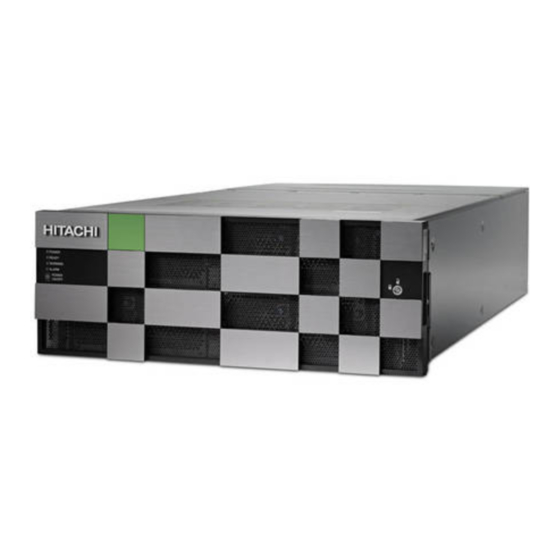
Hitachi Virtual Storage Platform G400, G600 hardware overview Hitachi Virtual Storage Platform G400, G600 are modular, rack-mountable, all-flash arrays that deliver high performance, high reliability, and flash- accelerated scalability. The storage system contain dual controllers, each controller contains its own processor, dual in-line cache memory modules (DIMMs), cache flash memory (CFM), battery, fans and iSCSI and Fibre Channel I/O modules. - Page 14 Features □ Scalability □ Hitachi Virtual Storage Platform G400, G600 hardware overview Hitachi Virtual Storage Platform G400, G600 Hardware Reference Guide...
-
Page 15: Block Configuration
• One or more drive trays for block-level storage • One 1U block service processor server (SVP) VSP G400 model The VSP G400 is a highly reliable storage system that offers high storage capacity with full redundancy to better protect data and manage storage operations. - Page 16 4U (174.3 mm) DB60 (power drive tray supply, contains BNST) • DW-F800- DB60C Related references • Examples of supported VSP G400 configurations on page 19 Hitachi Virtual Storage Platform G400, G600 hardware overview Hitachi Virtual Storage Platform G400, G600 Hardware Reference Guide...
-
Page 17: Vsp G600 Model
CBLM DW800-CBL DW-F800-CTLM 4U (174.3 mm) Controller Model number Description DW-F800-NAS Optional component for file storage configuration. NAS modules only provide file support. Hitachi Virtual Storage Platform G400, G600 hardware overview Hitachi Virtual Storage Platform G400, G600 Hardware Reference Guide... -
Page 18: Features
DB60C Related references • Examples of supported VSP G600 configurations on page 19 Features The features described in the table are included with VSP G400 and VSP G600. Feature Value Maximum cache memory supported VSP G400:128 GB VSP G600: 256 GB... -
Page 19: Scalability
576 HDDs or SSDs LFF drive tray 288 HDDs or SSDs FMD drive tray 288 HAF flash module drives Dense intermix drive tray Hitachi Virtual Storage Platform G400, G600 hardware overview Hitachi Virtual Storage Platform G400, G600 Hardware Reference Guide... -
Page 20: Maximum Number Of Mounted Drive Trays
720 HDDs or SSDs tray Note: The following SSD capacities (200 GB and 400 GB) are supported in a dense intermix drive tray. Hitachi Virtual Storage Platform G400, G600 hardware overview Hitachi Virtual Storage Platform G400, G600 Hardware Reference Guide... - Page 21 SFF drive + LFF drive + Dense intermix SFF, LFF drives dense intermix dense intermix drive tray drive tray drive tray CBLM Hitachi Virtual Storage Platform G400, G600 hardware overview Hitachi Virtual Storage Platform G400, G600 Hardware Reference Guide...
- Page 22 Hitachi Virtual Storage Platform G400, G600 hardware overview Hitachi Virtual Storage Platform G400, G600 Hardware Reference Guide...
-
Page 23: Virtual Storage Platform G400, G600 Controller
Virtual Storage Platform G400, G600 controller The Virtual Storage Platform G400, G600 models are equipped with dual controllers for communicating with a data host. Each controller includes the following internal components such as a processor, dual in-line cache memory modules (DIMMs), cache flash memory (CFM), battery, and fans. -
Page 24: Cblm Controller
(SIM) are issued: 452xxx, 462xxx, 3077xx, 4100xx, and 410100. LED might turn off during user maintenance. ALARM LED Off: Normal operation. Virtual Storage Platform G400, G600 controller Hitachi Virtual Storage Platform G400, G600 Hardware Reference Guide... -
Page 25: Cblm Front Panel Leds (Without Bezel)
(SIM) are issued: 452xxx, 462xxx, 3077xx, 4100xx, and 410100. Controller 1 (bottom) and Controllers Controller 2 (top). Virtual Storage Platform G400, G600 controller Hitachi Virtual Storage Platform G400, G600 Hardware Reference Guide... -
Page 26: Cblm Rear Panel
(for example, BKMF-10 and BKMF-20). CBLM rear panel The following table describes the definitions of the CBLM controller rear panel LEDs. Virtual Storage Platform G400, G600 controller Hitachi Virtual Storage Platform G400, G600 Hardware Reference Guide... - Page 27 Number Item Power supply unit Front end module Back end module LAN blade Rear view (includes NAS modules) Virtual Storage Platform G400, G600 controller Hitachi Virtual Storage Platform G400, G600 Hardware Reference Guide...
-
Page 28: Cblm Power Supply Unit Leds And Connectors
LEDs display the operating status of the storage system. Front end module descriptions The front end module LEDs display the operating status of the module. Virtual Storage Platform G400, G600 controller Hitachi Virtual Storage Platform G400, G600 Hardware Reference Guide... -
Page 29: 10-Gbps Iscsi Board Leds And Connectors (Optical)
Blue: Normal link status. Blink blue: Front end module is in communication status. iSCSI connectors Connect to Ethernet LAN cables. 10-Gbps iSCSI board LEDs and connectors (copper) Virtual Storage Platform G400, G600 controller Hitachi Virtual Storage Platform G400, G600 Hardware Reference Guide... -
Page 30: 8-Gbps, 16-Gbps, Or 32-Gbps Fibre Channel (4-Port) Board Leds And Connectors
Off: No link connection or not ready to communicate. iSCSI connectors Connect to Ethernet LAN cables. 8-Gbps, 16-Gbps, or 32-Gbps Fibre Channel (4-port) board LEDs and connectors Virtual Storage Platform G400, G600 controller Hitachi Virtual Storage Platform G400, G600 Hardware Reference Guide... - Page 31 PORT LED Red: Small form factor pluggable can be removed. Blue: Normal link status at 16- Gbps (16-Gbps). Blue: Normal link status at 32- Gbps (32-Gbps). Virtual Storage Platform G400, G600 controller Hitachi Virtual Storage Platform G400, G600 Hardware Reference Guide...
-
Page 32: 16-Gbps Fibre Channel (2-Port) Board Leds And Connectors
Port 4 CHB-1A CHB-1B CHB-1C CHB-1D CHB-1E CHB-1F CHB-1G CHB-1H CHB-2A CHB-2B CHB-2C CHB-2D CHB-2E CHB-2F CHB-2G CHB-2H 16-Gbps Fibre Channel (2-port) board LEDs and connectors Virtual Storage Platform G400, G600 controller Hitachi Virtual Storage Platform G400, G600 Hardware Reference Guide... -
Page 33: Lan Blade Leds And Connectors
Port 1 Port 2 CHB-1A CHB-1B CHB-1C CHB-1D CHB-1E CHB-1F CHB-1G CHB-1H CHB-2A CHB-2B CHB-2C CHB-2D CHB-2E CHB-2F CHB-2G CHB-2H LAN blade LEDs and connectors Virtual Storage Platform G400, G600 controller Hitachi Virtual Storage Platform G400, G600 Hardware Reference Guide... -
Page 34: Back End Module Leds And Connectors
Red: LAN blade can be removed. Uninterruptible power supply (UPS) port Back end module LEDs and connectors The back end module LEDs display the operating status of the module. Virtual Storage Platform G400, G600 controller Hitachi Virtual Storage Platform G400, G600 Hardware Reference Guide... - Page 35 Port LED Blue: Link status is normal. PATH 0 connector Connect to a drive tray. PATH 1 connector Connects to a drive tray. Virtual Storage Platform G400, G600 controller Hitachi Virtual Storage Platform G400, G600 Hardware Reference Guide...
- Page 36 Virtual Storage Platform G400, G600 controller Hitachi Virtual Storage Platform G400, G600 Hardware Reference Guide...
-
Page 37: Storage System Drive Trays
Large form-factor (LFF) drive tray □ Flash module drive (FMD) tray □ Dense intermix drive tray □ SFF and LFF AC power supply unit LEDs and connectors □ Storage system drive trays Hitachi Virtual Storage Platform G400, G600 Hardware Reference Guide... -
Page 38: Small Form-Factor (Sff) Drive Tray
Can be turned on or turned off by the maintenance utility. Lock Locks and unlocks the front panel bezel by using the supplied key. SFF front panel without bezel Storage system drive trays Hitachi Virtual Storage Platform G400, G600 Hardware Reference Guide... -
Page 39: Sff Rear Panel
Small form factor drives The twenty-four 2.5-inch small form factor drives are positioned vertically. The slots are organized from 0 to 23. SFF rear panel Storage system drive trays Hitachi Virtual Storage Platform G400, G600 Hardware Reference Guide... -
Page 40: Large Form-Factor (Lff) Drive Tray
Green: Normal operation. ALM LED Red: Power supply unit can be replaced. RDY LED Green: Normal operation. Large form-factor (LFF) drive tray LFF with front panel bezel Storage system drive trays Hitachi Virtual Storage Platform G400, G600 Hardware Reference Guide... -
Page 41: Lff Front Panel Without Bezel
LFF front panel without bezel Number Item Description POWER, READY, and LOCATE LEDs Green: Drive tray is powered Green: Drive tray is operational. Amber: Storage system drive trays Hitachi Virtual Storage Platform G400, G600 Hardware Reference Guide... -
Page 42: Lff Rear Panel
Can be turned on or turned off by the maintenance utility. ALARM LED Red: ENC can be replaced. PATH (IN) LED Blue: IN side port is linked up. Storage system drive trays Hitachi Virtual Storage Platform G400, G600 Hardware Reference Guide... -
Page 43: Flash Module Drive (Fmd) Tray
Green: Drive tray is operational. LOCATE LED Amber: • Indicates the location of the chassis. • Can be turned on or turned off by the maintenance utility. Storage system drive trays Hitachi Virtual Storage Platform G400, G600 Hardware Reference Guide... -
Page 44: Fmd Front Panel Without Bezel
If the storage system is turned on, the LED stops blinking when the capacitor is finished charging (approximately two minutes). Note: ACT indicator is only printed on some types of FMDs. Storage system drive trays Hitachi Virtual Storage Platform G400, G600 Hardware Reference Guide... -
Page 45: Fmd Rear Panel
6, 7, 8 3, 4, 5 0, 1, 2 FMD rear panel Number Item Description POWER LED Green: ENC is in the power-on state. LOCATE LED Amber: Storage system drive trays Hitachi Virtual Storage Platform G400, G600 Hardware Reference Guide... -
Page 46: Dense Intermix Drive Tray
AC IN LED operating normally. ALM REPLACE LED Red: Power supply unit can be replaced. Dense intermix drive tray Dense intermix drive tray with front panel bezel Storage system drive trays Hitachi Virtual Storage Platform G400, G600 Hardware Reference Guide... -
Page 47: Dense Intermix Drive Tray Display Leds
Dense intermix drive tray display LEDs Number Item Description Green: Normal operation. Blink green: Drive is being accessed. ALM LED Red: Drive stopped due to a failure and can be replaced. Storage system drive trays Hitachi Virtual Storage Platform G400, G600 Hardware Reference Guide... -
Page 48: Dense Intermix Drive Tray Rear Panel
PATH (OUT) connector Connect to a drive tray. PATH (IN) LED Blue: IN side port is linked up. PATH (IN) connector Connects to a controller or drive tray. Storage system drive trays Hitachi Virtual Storage Platform G400, G600 Hardware Reference Guide... -
Page 49: Sff And Lff Ac Power Supply Unit Leds And Connectors
AC power supply units include LEDs to display its operating status. Number Item Description Green: Normal operation. RDY LED AC IN LED Green: AC input is operating normally. Red: Power supply unit can be ALM LED replaced. Storage system drive trays Hitachi Virtual Storage Platform G400, G600 Hardware Reference Guide... - Page 50 Storage system drive trays Hitachi Virtual Storage Platform G400, G600 Hardware Reference Guide...
-
Page 51: Host Port Expansion Chassis
Host port expansion chassis front panel bezel LEDs □ PCIe switchboard □ Host port expansion chassis fan □ PCIe cable connector □ Host port expansion chassis power supply □ Host port expansion chassis Hitachi Virtual Storage Platform G400, G600 Hardware Reference Guide... -
Page 52: Host Port Expansion Chassis Front Panel Bezel Leds
Green: Host port expansion is POWER LED turned on. Amber: PCIe module is turned Off: PCIe module is turned off. Lock or unlock the front bezel. Safety lock PCIe switchboard Host port expansion chassis Hitachi Virtual Storage Platform G400, G600 Hardware Reference Guide... -
Page 53: Host Port Expansion Chassis Fan
Off: PCIe switchboard is powered off. Host port expansion chassis fan Number Item Description ALM LED Red: Fan failure has occurred. Off: Normal operation. PCIe cable connector Host port expansion chassis Hitachi Virtual Storage Platform G400, G600 Hardware Reference Guide... - Page 54 Off: Basic PCIe is normal or not set. Link Option LED Green: Option PCIe Gen-3.0 (8- Gbps) is linked up normally. Off: Option PCIe is not linked up (PCIe cable might not be Host port expansion chassis Hitachi Virtual Storage Platform G400, G600 Hardware Reference Guide...
-
Page 55: Host Port Expansion Chassis Power Supply
Number Item Description ALM/RDY LED Red: Host port expansion chassis power supply can be replaced safely. Green: Normal operation. AC IN LED Blue: AC input is normal. Host port expansion chassis Hitachi Virtual Storage Platform G400, G600 Hardware Reference Guide... - Page 56 Host port expansion chassis Hitachi Virtual Storage Platform G400, G600 Hardware Reference Guide...
-
Page 57: Nas Module
The NAS module provides communication ports to support file system protocols in a block- or file-system configuration. Note: The NAS module is not supported on the VSP G200 storage system. NAS Module Ports and LEDs □ NAS module Hitachi Virtual Storage Platform G400, G600 Hardware Reference Guide... -
Page 58: Nas Module Ports And Leds
Reserved for future use Status LED Green NAS modules are functioning normally. NAS modules can be removed. Link LED Blue Displays link status. Fail LED A failure has occurred. NAS module Hitachi Virtual Storage Platform G400, G600 Hardware Reference Guide... -
Page 59: Vsp Service Processor Server
The SVP is available as: • A physical 1U management server provided by Hitachi Data Systems that runs Windows Embedded Standard 7. • A software application that runs Windows 7 Professional x64 Service Pack 1 (64-bit) on a customer-supplied server hardware, a VMware ESXi host, or Linux KVM host. -
Page 60: Service Processor Description
• Turning on automatic Windows updates or using the manual Windows update method. • Installing antivirus software that has been tested and approved by Hitachi. SVP front panel The front panel of the physical SVP is equipped with LEDs, a reset button, and a power button. -
Page 61: Svp Rear Panel
LAN ports. Number Description Power socket. Attach the power cable supplied with the SVP. Four LAN ports arranged as follows: LAN3 LAN4 LAN1 LAN2 VSP service processor server Hitachi Virtual Storage Platform G400, G600 Hardware Reference Guide... -
Page 62: Service Processor Hardware Specifications
2 TB Network interface card x4 ports (on-board NIC) + x1 IPMI (BMC) port Fans 2 x 4-cm 4-pin PWM fans Operating system Windows Embedded Standard 7 VSP service processor server Hitachi Virtual Storage Platform G400, G600 Hardware Reference Guide... -
Page 63: Maintaining The Storage System
For more complex maintenance activities, contact customer support. Storing the storage system □ Powering off the storage system □ Removing cables □ Maintaining the storage system Hitachi Virtual Storage Platform G400, G600 Hardware Reference Guide... -
Page 64: Storing The Storage System
Observe the following instructions when removing cables form the storage system. To remove a SAS cable, pull the tab of the SAS cable (1) to release the latch and remove the SAS cable (2). Maintaining the storage system Hitachi Virtual Storage Platform G400, G600 Hardware Reference Guide... - Page 65 (1) to release the latch and remove the SAS cable (2). To remove a LAN cable, push the top of the LAN cable connector (1) to release the latch and remove the LAN cable (2). Maintaining the storage system Hitachi Virtual Storage Platform G400, G600 Hardware Reference Guide...
- Page 66 Maintaining the storage system Hitachi Virtual Storage Platform G400, G600 Hardware Reference Guide...
-
Page 67: Mechanical Specifications For Vsp G400, G600
Mechanical specifications for VSP G400, G600 The storage system mechanical specifications are described for VSP G400, G600 . VSP G400 and VSP G600 mechanical specifications □ Mechanical specifications for VSP G400, G600 Hitachi Virtual Storage Platform G400, G600 Hardware Reference Guide... -
Page 68: Vsp G400 And Vsp G600 Mechanical Specifications
ENC and AC-DC power supplies equipped with built-in cooling fans. NAS module Component Description Optional component for block and file storage NAS module configuration Mechanical specifications for VSP G400, G600 Hitachi Virtual Storage Platform G400, G600 Hardware Reference Guide... - Page 69 Maximum mountable quantity Mixing SFF, LFF, FMD, and dense intermix drive trays might affect the maximum number of drives that can be mounted. Component Specification Mechanical specifications for VSP G400, G600 Hitachi Virtual Storage Platform G400, G600 Hardware Reference Guide...
-
Page 70: Battery Specifications
10-Gbps optical iSCSI 10-Gbps copper iSCSI 8-Gbps Fibre Channel optical Number of ports (NAS Module not installed) 16-Gbps Fibre Channel optical (2-port) 16-Gbps Fibre Channel optical (4-port) Mechanical specifications for VSP G400, G600 Hitachi Virtual Storage Platform G400, G600 Hardware Reference Guide... -
Page 71: Raid Specifications
3 TB (or 4 TB when using the LDEVs of other storage systems) Maximum volumes/host groups and iSCSI 2048 targets Maximum number of volumes per RAID group 2048 Mechanical specifications for VSP G400, G600 Hitachi Virtual Storage Platform G400, G600 Hardware Reference Guide... - Page 72 The table lists the values of a maximum configuration when all controllers and drives are mounted. Component Specification CBLM 187.39 pounds (85 kg) Approx 50.70 inches (23 kg) Approx 59.52 inches (27 kg) Approx. 83.77 pounds (38 kg) Mechanical specifications for VSP G400, G600 Hitachi Virtual Storage Platform G400, G600 Hardware Reference Guide...
- Page 73 Write Cache function disabled. When the battery is charged, the warning indication disappears, and the storage system continues the operation in the Write Cache function. Mechanical specifications for VSP G400, G600 Hitachi Virtual Storage Platform G400, G600 Hardware Reference Guide...
- Page 74 3 hours every six months. Insulation performance Item Specification Insulation withstand voltage AC 1,500 V (100 mA, 1 min) Insulation resistance DC 500 V, 10 M Ω or more Mechanical specifications for VSP G400, G600 Hitachi Virtual Storage Platform G400, G600 Hardware Reference Guide...
-
Page 75: B Electrical Specifications For Vsp G400, G600
Electrical specifications for VSP G400, G600 The electrical specifications are described for the storage systems. Electrical specifications □ Electrical specifications for VSP G400, G600 Hitachi Virtual Storage Platform G400, G600 Hardware Reference Guide... -
Page 76: Electrical Specifications
This table shows the power requirement (100 V or 200 V) for the maximum configuration . The actual required power might exceed the value shown in the table when the tolerance is included. Electrical specifications for VSP G400, G600 Hitachi Virtual Storage Platform G400, G600 Hardware Reference Guide... -
Page 77: C Environmental Specifications For Vsp G400, G600
Environmental specifications for VSP G400, G600 The environmental specifications are described for the storage systems. Environmental specifications □ Environmental specifications for VSP G400, G600 Hitachi Virtual Storage Platform G400, G600 Hardware Reference Guide... -
Page 78: Environmental Specifications
Transport, storage -22°F to 140°F -22°F to 122°F (-30°C to 50°C) (-30°C to 60°C) Temperature 10 or less change rate (°C/h) Humidity State Percentage Operating 8 to 80 Environmental specifications for VSP G400, G600 Hitachi Virtual Storage Platform G400, G600 Hardware Reference Guide... - Page 79 DKC-F710I-1R6FM or DKC-F710I-3R2FM drive is installed. (Environmental temperature: 10°C to 40°C) 3,000 3,000 (Environmental temperature: 10°C to 32°C) Operating (m) (Environmental temperature: 10°C to 32°C) Environmental specifications for VSP G400, G600 Hitachi Virtual Storage Platform G400, G600 Hardware Reference Guide...
-
Page 80: Acoustic Noise
7.2 B to 8.1 B, according to the ambient temperature, drive configuration, and operating status. When accessing the dense intermix drive tray, do not work for long times at the rear of the rack. Environmental specifications for VSP G400, G600 Hitachi Virtual Storage Platform G400, G600 Hardware Reference Guide... - Page 81 Acoustic power level (LwA) measured by the ISO 7779 standard is 7.2 B. This value changes from 7.2 B to 8.1 B, according to the ambient temperature, drive configuration, and operating status. Environmental specifications for VSP G400, G600 Hitachi Virtual Storage Platform G400, G600 Hardware Reference Guide...
- Page 82 Environmental specifications for VSP G400, G600 Hitachi Virtual Storage Platform G400, G600 Hardware Reference Guide...
-
Page 83: D Iscsi Standards And Specifications
The following tables describe the standards and specifications for using iSCSI in a hosting environment. iSCSI standards □ iSCSI specifications □ iSCSI standards and specifications Hitachi Virtual Storage Platform G400, G600 Hardware Reference Guide... -
Page 84: Iscsi Standards
Path I/O) Link 10 Gbps SFP+ Transfer speed 10 Gbps Connector type Cable Optical OM3, OM2 MMF cable Network switch L2 or L3 switch Should comply with IEEE802.3ae iSCSI standards and specifications Hitachi Virtual Storage Platform G400, G600 Hardware Reference Guide... - Page 85 The setting of the corresponding host should also be changed to log in the new port number. • The new port number might conflict with other network communication or be iSCSI standards and specifications Hitachi Virtual Storage Platform G400, G600 Hardware Reference Guide...
- Page 86 Example: iqn.1994-04.jp.co.hitachi:rsd.d7m.t.10020.1b000.tar eui: 64-bit Extended Unique Identifier. The eui consists of a type identifier, "eui," and an ASCII-coded, hexadecimal, EUI-64 identifier. Example: eui.0123456789abcdef iSCSI standards and specifications Hitachi Virtual Storage Platform G400, G600 Hardware Reference Guide...
-
Page 87: Replacement Parts
Replacement parts Part replacement is essential for maintaining the high performance of the system. Replacing system components is covered by the maintenance service contract. Battery unit □ Replacement parts Hitachi Virtual Storage Platform G400, G600 Hardware Reference Guide... -
Page 88: Battery Unit
If not, the battery might reach its lifespan earlier than expected and become unusable within three years. When replacing the battery, follow the given procedure for disposing a used battery. Replacement parts Hitachi Virtual Storage Platform G400, G600 Hardware Reference Guide... -
Page 89: F Data And Power Cables
The storage system supports a variety of data and power cables for specific hosting environments. Fibre Channel cables □ iSCSI cables □ Managing data cables □ AC power cables □ Data and power cables Hitachi Virtual Storage Platform G400, G600 Hardware Reference Guide... -
Page 90: Fibre Channel Cables
If this default value is set, Fabric is set to ON automatically. Note: To connect to the server by the 16-Gbps direct connection, the Fabric Emulation function of the Hitachi host adapter is required. Data and power cables Hitachi Virtual Storage Platform G400, G600 Hardware Reference Guide... - Page 91 Gbps. If this default value is set, Fabric is set to ON automatically. Note: The five Hitachi FC HBAs also have an alternate option of Fabric Emulation. When the HBA is configured to use this mode, treat it as an attached switch and set the storage port to Fabric = On and Connection Type = P-to-P.
- Page 92 One side Other side LC-LC cable Optical Equivalent to 50, 125 μm, LC connector LC connector (shortwave) DXLC-2P-PC- 62.5, 125 μm xxM-GC50, Multimode Wavelength: 125-2SR 850 nm (OMx) Data and power cables Hitachi Virtual Storage Platform G400, G600 Hardware Reference Guide...
-
Page 93: Iscsi Cables
• Connector type: LC duplex receptacle connector • Interval: 6.25 mm flat type, two rows iSCSI cables When constructing an iSCSI system with a direct connection or switch connection, consider the following: Data and power cables Hitachi Virtual Storage Platform G400, G600 Hardware Reference Guide... - Page 94 The following figure shows the type of optical connector that connects the storage system optical iSCSI ports. • LC connector type • Connector type: LC duplex receptacle connector • Interval: 6.25 mm flat type, two rows Data and power cables Hitachi Virtual Storage Platform G400, G600 Hardware Reference Guide...
-
Page 95: Managing Data Cables
1.73 inch (40 mm) Protecting cables Damage to your Fibre Channel and Ethernet cables can affect the performance of your storage system. Observe the following guidelines to protect cables Data and power cables Hitachi Virtual Storage Platform G400, G600 Hardware Reference Guide... - Page 96 When cabling full-width modules, such as NAS modules as shown in the following figure, route the cables horizontally, so that they do not interfere when replacing a module. Data and power cables Hitachi Virtual Storage Platform G400, G600 Hardware Reference Guide...
-
Page 97: Ac Power Cables
AC power cables Utility AC power standards for connector types and voltage levels vary by country. Hitachi provides a variety of power cables that facilitate using storage systems around the world. Hitachi power cables meet the safety standards for the country for which they are intended. - Page 98 Also Malaysia and Ireland. Also known as "Schuko" connector and used in Austria, Belgium, Finland, France, Germany, Greece, Hungary, Indonesia, Netherlands, Norway, Poland, Portugal, Russia, Spain, and Sweden. Data and power cables Hitachi Virtual Storage Platform G400, G600 Hardware Reference Guide...
-
Page 99: Ac Connections
1 ANSI C73.11 2 NEMA 6-15P 3 IEC 83 CEE 7/7 200V-240V 4 CEE (7) II, IV, VII 3 IEC 83 BS-1363 200V-240V 5 BS 1365 3IEC 83 Data and power cables Hitachi Virtual Storage Platform G400, G600 Hardware Reference Guide... -
Page 100: Power Cable Usage Guidelines
6 AS C112 Power cable usage guidelines Hitachi storage systems are intended for rack installation and ship with power cords. Installation and service requirements may require additional cords and cables to be ordered. The type of power cable required by a given installation is determined primarily by the: •... -
Page 101: Cable Management
These straps, shown in the following image, loop around the neck of a power cable connector, and the notched tail is slipped over the hook of the restraining bar fixed to the storage system. Data and power cables Hitachi Virtual Storage Platform G400, G600 Hardware Reference Guide... - Page 102 Data and power cables Hitachi Virtual Storage Platform G400, G600 Hardware Reference Guide...
-
Page 103: G Port Address Mapping
Port address mapping Port address mapping □ Port address mapping Hitachi Virtual Storage Platform G400, G600 Hardware Reference Guide... -
Page 104: Port Address Mapping
HBA, the host might not be able to recognize the VOL. If this problem or other problems occur, revert to the default value of EF. * A value set as the default value. Port address mapping Hitachi Virtual Storage Platform G400, G600 Hardware Reference Guide... -
Page 105: H Third-Party Racks
Third-party rack support for VSP Gx00 models □ Hitachi Universal V2 Rack rail kits □ Hitachi Universal V2 Rack accessories □ Third-party rack support for DB60 dense intermix drive trays □ Third-party racks Hitachi Virtual Storage Platform G400, G600 Hardware Reference Guide... -
Page 106: Third-Party Rack Support For Vsp Gx00 Models
PDUs and cable loops. Hitachi Universal V2 Rack rail kits Use rail kits to mount the Hitachi Virtual Storage Platform family storage system in a Hitachi Universal V2 Rack. The following tables list the rail kit information for the specified storage systems. -
Page 107: Third-Party Rack Support For Db60 Dense Intermix Drive Trays
• Dense tray rail kits require square mounting holed racks. • Use a ladder to service the DB60 dense intermix drive tray if the drive tray is mounted above shelf height RU32. Third-party racks Hitachi Virtual Storage Platform G400, G600 Hardware Reference Guide... - Page 108 Third-party racks Hitachi Virtual Storage Platform G400, G600 Hardware Reference Guide...
-
Page 109: I Hitachi Universal V2 Rack Power Distribution Units
Hitachi Universal V2 Rack power distribution units The Hitachi Universal V2 Rack is equipped with specific power distribution units (PDU) for Americas, APAC, and EMEA regions. The PDUs can provide electrical power to the storage system in a single-phase or three-phase configuration. -
Page 110: Americas Single-Phase Pdu 1P30A-8C13-3C19Ul.p
Americas single-phase PDU 1P30A-8C13-3C19UL.P The following figure and table describes the specifications of the PDU. Figure 1 Americas PDU for the Hitachi Universal V2 Rack (Single-phase PDU 1P30A-8C13-3C19UL.P) Part Number Region Phase Description 1P30A-8C13-3C19UL.P Americas Single • 208V, 30A (24A rated) 60Hz •... -
Page 111: Americas Three-Phase Pdu 3P30A-8C13-3C19Ul.p
• 4.5 m (14.76 feet) cable Americas three-phase PDU 3P30A-8C13-3C19UL.P The following figure and table describes the specifications of the PDU. Figure 3 Americas PDU for the Hitachi Universal V2 Rack (Three-phase PDU 3P30A-8C13-3C19UL.P) Part Number Region Phase Description 3P30A-8C13-3C19UL.P... -
Page 112: Americas Three-Phase Pdu 3P30A-24C13-6C19Ul.p
Figure 4 Americas PDU for the Hitachi Universal V2 Rack (Three-phase PDU 3P30A-15C13-3C19UL.P) Part Number Region Phase Description 3P30A-15C13-3C19UL. Americas Three • 208V 3P, 30A (24A rated) 60Hz • 15 IEC C13 + 3 IEC C19 sockets • NEMA L15-30P input power plug •... -
Page 113: Apac And Emea Single-Phase Pdu 1P32A-9C13-3C19Ce.p
APAC and EMEA single-phase PDU 1P32A-9C13-3C19CE.P The following figure and table describes the specifications of the PDU. Figure 6 APAC and EMEA PDU for the Hitachi Universal V2 Rack (Single- phase 1P32A-9C13-3C19CE.P) Part Number Region Phase Description 1P32A-9C13-3C19CE.P APAC and EMEA Single •... -
Page 114: Apac And Emea Three-Phase Pdu 3P16A-9C13-3C19Ce.p
4.5 m (14.76 feet) cable APAC and EMEA three-phase PDU 3P16A-9C13-3C19CE.P The following figure and table describes the specifications of the PDU. Figure 8 APAC and EMEA PDU for the Hitachi Universal V2 Rack (Three- phase 3P16A-9C13-3C19CE.P) Part Number Region... -
Page 115: Apac And Emea Three-Phase Pdu 3P32A-24C13-6C19Ce.p
Figure 9 APAC and EMEA PDU for the Hitachi Universal V2 Rack (Three- phase 3P16A-15C13-3C19CE.P) Part Number Region Phase Description 3P16A-15C13-3C19CE. APAC and EMEA Three • 400V max. 3x 16A 50Hz / 60Hz • 15 IEC C13 + 3 IEC C19 sockets •... - Page 116 Hitachi Universal V2 Rack power distribution units Hitachi Virtual Storage Platform G400, G600 Hardware Reference Guide...
-
Page 117: J Regulatory Compliance
EN61000-3.2:2006+A1 EN61000-3.3:2008 Safety certifications UL and CSA cTUVus USA and Canada 60950-1:2007 EN60950-1:2006+A1 Germany IEC60950-1:2005+A1 All CB countries IEC60950-1:2005+A1 S-Mark Argentina TP TC 004/2011 Russia CNS 14336-1 BSMI Taiwan Regulatory compliance Hitachi Virtual Storage Platform G400, G600 Hardware Reference Guide... - Page 118 Product marking or Standard Specification Country regulation logo EN60950-1:2006+A1 Radio interference VCCI V-3/2013.04 VCCI Japan voluntary control Regulatory compliance Hitachi Virtual Storage Platform G400, G600 Hardware Reference Guide...
-
Page 119: Index
43 CBLH controller 25 rear panel 45 rear panel 26 with front panel bezel 43 CBLM controller 24, 25 without front panel bezel 44 rear panel 26 Index Hitachi Virtual Storage Platform G400, G600 Hardware Reference Guide... - Page 120 95 replacement parts 87 maximum battery unit 88 number of mounted drives 20 retention, cables 101 mechanical 67 mechanical specifications 68 module 57, 58 mounted drive trays 20 Index Hitachi Virtual Storage Platform G400, G600 Hardware Reference Guide...
- Page 121 62 third-party rack DB60 dense intermix drive tray 107 third-party racks 105 third-party racksmounting guidelines 106 Unified 15 Virtual Storage Platform G400, G600 23 without front panel bezel 25 Index Hitachi Virtual Storage Platform G400, G600 Hardware Reference Guide...
- Page 122 Index Hitachi Virtual Storage Platform G400, G600 Hardware Reference Guide...
- Page 123 Hitachi Virtual Storage Platform G400, G600 Hardware Reference Guide...
- Page 124 Hitachi Vantara Corporate Headquarters Regional Contact Information 2845 Lafayette Street Americas: +1 866 374 5822 or info@hitachivantara.com Santa Clara, CA 95050-2639 USA Europe, Middle East and Africa: +44 (0) 1753 618000 or info.emea@hitachivantara.com www.HitachiVantara.com Asia Pacific: +852 3189 7900 or info.marketing.apac@hitachivantara.com...