Table of Contents
Advertisement
Page 1
Page 1
SERVICE MANUAL
MC 46
Electronic
modular cubers
New PC Board
From s.n. 28850
Scotsman Ice Srl
Via Lainate, 31 - 20010 Pogliano M.se - Milano - Italy
Tel. +39-02-93960.1 (Aut. Sel.)- Telefax +39-02-93550500
Direct Line to Service & Parts:
Phone +39-02-93960350 - Fax +39-02-93540449
Website: www.scotsman-ice.it
E-Mail: scotsman.europe@scotsman.it
REV. 09/2015
Advertisement
Table of Contents

Related Manuals for Scotsman MCS 46 A


Summary of Contents for Scotsman MCS 46 A
- Page 1 Electronic modular cubers New PC Board From s.n. 28850 Scotsman Ice Srl Via Lainate, 31 - 20010 Pogliano M.se - Milano - Italy Tel. +39-02-93960.1 (Aut. Sel.)- Telefax +39-02-93550500 Direct Line to Service & Parts: Phone +39-02-93960350 - Fax +39-02-93540449 Website: www.scotsman-ice.it...
- Page 2 DIP SWITCH MCS 16 A MCS 16 W MCM 16 A MCM 16 W MCL 16 A MCL 16 W MCS 46 A MCS 46 W MCM 46-1210 A MCM 46-1210 W MCL 46-1210 A MCL 46-1210 W MCXL 46 W...
-
Page 3: Table Of Contents
Page 2 Page 2 TABLE OF Table of contents CONTENTS Specifications MC 46 GENERAL INFORMATION AND INSTALLATION Introduction Unpacking and Inspection - Ice maker Unpacking and Inspection - Storage bin Location and levelling Stacking installation Electrical connections Water supply and drain connections Final check list Installation practice OPERATING INSTRUCTIONS... - Page 4 NOTE. The daily ice-making capacity is directly related to the condenser air inlet temperature, water temperature and age of the machine. To keep your SCOTSMAN MODULAR CUBER at peak performance levels, periodic maintenance checks must be carried out as indicated on maintenance section of this manual.
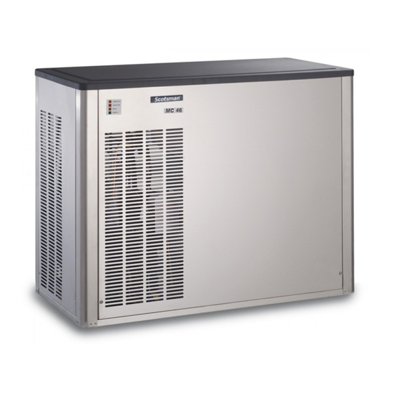
- Page 5 Page 4 Page 4 SPECIFICATIONS ACCESSORIES KSC 11: Cube stacking kit DIMENSIONS: HEIGHT 874 mm. WIDTH 1074 mm. DEPTH 534 mm. WEIGHT 185 Kgs. MC 46 - MACHINE SPECIFICATIONS Model Cond. unit Finish Comp. HP Water req. - lt/24 HR MC 46 AS 6 Stainless steel MC 46 WS 6...
-
Page 6: General Information And Installation
Model and Serial Number necessary to use an auxiliary bin such as the Bin taken from the data plate. SB 550. Forward the completed self-addressed registration card to Frimont/Scotsman Europe factory. UNPACKING AND INSPECTION Modular Cuber C. LOCATION AND LEVELLING Call your authorized SCOTSMAN Distributor WARNING. -
Page 7: Stacking Installation
Page 6 Page 6 STACKING INSTALLATION Level the Storage Bin Assy in both the left to right and front to rear directions by means of A Stacking Kit KSC 11 is available as an accessory the adjustable legs. on request to allow the installation of two Modular Cubers one on top of the other. - Page 8 Page 7 Page 7...
-
Page 9: Electrical Connections
(1/4" pitch per foot). a solid earth wire. A vent at the unit drain connection is also required All SCOTSMAN ice machines are supplied from for proper sump drainage. the factory completely pre-wired and require only electrical power connections to the wire cord Water drain - Water cooled models provided at the rear of the unit. -
Page 10: Installation Practice
Page 9 Page 9 H. INSTALLATION PRACTICE 1. Hand shut-off valve 2. Water filter 3. Water supply line (flexible hose) 4. 3/4" gas male fitting 5. Power line 6. Main switch 7/9. Drain fitting 8/10. Vented drain line 11. Open trapped vented drain WARNING. -
Page 11: Operating Instructions
Page 10 Page 10 OPERATING INSTRUCTIONS Give power to the unit to start it up by NOTE. Ice maker pcb is equipped by jumper switching "ON" the power line main disconnect cleaning reminding setting (see pag. 20) switch. suitable to alert users after certain time of unit operation. -
Page 12: Operatiobnal Checks
Page 11 Page 11 NOTE . If in the 5 minutes length of the water NOTE. On air cooled models the condenser filling phase the machine sump reservoir temperature sensor, which is located within does not get filled with water up to the rim of the condenser fins, keep the head the overflow pipe, it is advisable to check: (condensing) pressure between 16 and 18... - Page 13 Page 12 Page 12 Check to see through the ice discharge The ice making process takes place thereby, opening that the self propeller spray bar is with the water sprayed into the molds that gets correctly rotating and that the water jets uniformely gradually refrigerated by the heat exchange with the refrigerant flowing into the evaporator reach the interior of the inverted mold cups and...
- Page 14 Page 13 Page 13 During the freezing process, when the evaporator After about 17-20 minutes from the beginning of the freezing cycle, in an hypothetic temperature falls below an established value, to ambient temperature of 21°C , the defrost cycle the evaporator temperature sensor supplies a takes place with the hot gas and the water inlet low voltage power signal to the electronic control...
- Page 15 Page 14 Page 14 Check the texture of ice cubes just released. NOTE. The ICE LEVEL CONTROL They have to be in the right shape with a small (INFRARED SYSTEM) is independent of the depression of about 5-6 mm in their crown. temperature however, the reliability of its If not, wait for the completion of the second cycle detection can be affected by external light...
-
Page 16: Freezing Cycle
When the temperature of the evaporator How it works serpentine drops to a pre-set value, the evaporator In the SCOTSMAN Modular Cubers the water sensor probe changes its electrical resistance used to make the ice is kept constantly in allowing a low voltage current (12 volts) to flow to circulation by an electric water pump which primes the P.C. - Page 17 Page 16 Page 16...
-
Page 18: Harvest Cycle
Page 17 Page 17 The electrical components in operation during At the start of the freezing cycle the refrigerant the freezing cycle are: suction or lo-pressure lowers rapidly to 2.5 bars- 35 psig then it declines gradually - in relation with COMPRESSOR the growing of the ice thickness - to reach, at the ÷... -
Page 19: Control Sequence
Page 18 Page 18 Meanwhile, the refrigerant as hot gas, discharged TIMED FREEZE from the compressor, flows through the hot gas valve directly into the evaporator serpentine by- passing the condenser. Electrical components (Loads) . ON OFF The hot gas circulating into the serpentine of the •... -
Page 20: Component Description
Page 19 Page 19 The activation of the electronic timer (-15°C - Freeze Cycle 5°F) is monitored by the lighting up of the RED LED placed in the front of the P.C. BOARD. Average Discharge This lighting up occures usually in the mid period Pressure A/C: 16÷18 bars (225÷250 psig) of the freezing cycle and signals the switching... - Page 21 Page 20 Page 20 P.C. BOARD (Data processor) leads of the sensor probes and input and output The P.C. BOARD, fitted in its plastic box located terminals for the leads of the ice maker electrical in the front of the unit, consists of two separated wires.
- Page 22 Page 21 Page 21 PUSH BUTTON OPERATION REASON WHY STATUS DURING WATER FILLING PHASE • Push for more then 2” but less then 5” the ON STEADY UNIT UNDER POWER machine enters in Cleaning Mode • Push for more then 5” the machine by-pass the Water Filling Phase ON STEADY FREEZING CYCLE...
- Page 23 Page 22 Page 22 WATER SPRAY SYSTEM size of the cubes (Large or Medium) as per the following setting: Through its nozzles, the water pumped, is sprayed ON : PROGRAM A in each individual cup to be frozen into ice. OFF : PROGRAM B It consists of one spray tube wheve are located OFF OFF : PROGRAM C...
- Page 24 Page 23 Page 23 During the defrost cycle the hot gas valve coil is CONTACTOR activated so to attract the hot gas valve piston in order to give way to the hot gas discharged from Placed outside of the control box it is controlled the compressor to flow directly into the evaporator by the P.C.
-
Page 25: Adjustment, Removal And Replacement Procedures
Page 24 Page 24 ADJUSTMENT, REMOVAL AND REPLACEMENT PROCEDURES ADJUSTMENT OF THE CUBE SIZE CAUTION. Before performing actual adjustment of the cube size, check other possible causes for cube size problems, refer to the Service Diagnosis Section for problem review and analysis. Do not perform any adjustment till the icemaking system has progressed SMALL... -
Page 26: Wiring Diagram
Page 25 Page 25 WIRING DIAGRAM MC-46 A-W 230/50/1... - Page 27 Page 26 Page 26 WIRING DIAGRAM MC-46 A-W 230/60/1...
- Page 28 Page 27 Page 27 WIRING DIAGRAM MC-46 A-W 220/50-60/3 - 400/50/3 + N...
-
Page 29: Service Diagnosis
Shortage of water See remedies for shortage of water Dirty water supply Use water softner or water filter Accumulated impurities Use SCOTSMAN Ice Machine cleaner Shortage of water Water spilling out through curtain Check or replace curtain Water solenoid valve not opening... - Page 30 Page 29 Page 29 SERVICE DIAGNOSIS SYMPTON POSSIBLE CAUSE SUGGESTED CORRECTION Irregular cubes size & some Some jets plugged Remove spray bar & jet bearing cloudy and clean them Shortage of water See shortage of water Unit not level Level as required Spray bar not rotating Remove spray bar &...
-
Page 31: Maintenance And Cleaning Instructions
Perform adjustment of DIP SWITCH keys Clean the water system, evaporators, bin as required. and spray bar/s using a solution of SCOTSMAN Ice Machine Cleaner. Check the ice level control sensor to test Refer to procedure C cleaning instructions and shut-off. -
Page 32: Cleaning Instructions Of Water System
Cleaning Mode (Fig.7) cleaning solution by diluting in a plastic container two or three liters of warm water (45°-50°C) with a 0,2-0,3 liters of SCOTSMAN Ice Machine Cleaner. WARNING. The SCOTSMAN Ice Machine Cleaner contains Phosphoric and Hydroxyacetic acids. - Page 33 Page 32 Page 32 14. Flush out the rinsing solution from the sump With the system in Cleaning mode the reservoirs water pump is the only component in operation to circulate the cleaning solution in the entire 15. Place again the evaporator cover and the water system unit service panels.
- Page 34 Page 33 Page 33 Sanitation 22. At completion of the freezing and harvest cycle make sure of proper texture and clearness of the ice cubes and that, they do not have any acid taste. NOTE. Sanitation of the water system is recommended to be done once a month.