
Related Manuals for Electrolux T3900


Summary of Contents for Electrolux T3900
- Page 1 SERVICE MANUAL T3900/T31200 TD100/TD135 487 03 29 41.01 Dryer type T3900/TD100 up to serial number: 20900/0000490 Dryer type T31200/TD135 up to serial number: 21200/0001034...
-
Page 3: Table Of Contents
Safety instructions Overview Technical data Description of principal components Periodic maintenance Service instructions Error codes (See Selecta Control service manual) Controls. Troubleshooting Machine units and components Overheating thermostat - thermostat sensor Door switch and filter drawer switch Motor Heating system Drum with bearing Cabinet, Sliding Door: Adjusting doors, replacing wire Tilting function Gas system... - Page 5 Service 1. Safety instructions manual Content Safety instructions ........487 03 29 41...
-
Page 7: Safety Instructions
Service 1. Safety instructions manual Safety instructions This machine is only intended for drying water-washed garments. Clothes that have been cleaned with chemicals/flammable liquids, must NOT be dried in the machine. Remove clothes from the tumble dryer as soon as they are dry. This prevents them from becoming creased, and reduces the risk of spontaneous ignition. -
Page 9: Technical Data
Content Technical data, type T3900 ....... . Technical data, type T31200 ....... -
Page 11: Technical Data, Type T3900
Service 2. Technical data manual Technical data - type T3900 Heating Steam Electric 900 litres 900 litres 900 litres Drum volume: Basic: Standard door 440 kg 440 kg 440 kg Weight net: Basic: Sliding Door 494 kg 494 kg 494 kg... -
Page 12: Technical Data, Type T31200
Service 2. Technical data manual Technical data - type T31200 Heating Steam Electric 1200 litres 1200 litres 1200 litres Drum volume: Basic: Standard door 470 kg 470 kg 470 kg Weight net: Basic: Sliding Door 524 kg 524 kg 524 kg Heating unit 46 kg 50 kg... -
Page 13: Technical Data, Type Td100
Service 2. Technical data manual Technical data - type TD100 Heating Steam Electric (900 litres) 32 cu.ft 32 cu.ft 32 cu.ft Drum volume: Basic: Standard door (440 kg) 970 lb 970 lb 970 lb Weight net: Basic: Sliding Door (494 kg) 1087 lb 1087 lb 1087 lb... -
Page 14: Technical Data, Type Td135
Service 2. Technical data manual Technical data - type TD135 Heating Steam Electric Drum volume: (1200 litres) 42.4 cu.ft 42.4 cu.ft 42.4 cu.ft Basic: Standard door (470 kg) 1036 lb 1036 lb 1036 lb Weight net: Basic: Sliding Door (524 kg) 1153 lb 1153 lb 1153 lb... - Page 15 Service 3. Description of principal components manual Content Description ......... . . Sliding Door and Tilt .
-
Page 17: Description
This service manual deals with two types of dryers: • 900 litres T3900 / TD100 • 1200 litres T31200 / TD135. Dryer types T3900 / TD100 and T31200 / TD135 are available as electric heated, gas heated or steam heated. Both types with ordinary vent into the air. -
Page 18: Sliding Door And Tilt
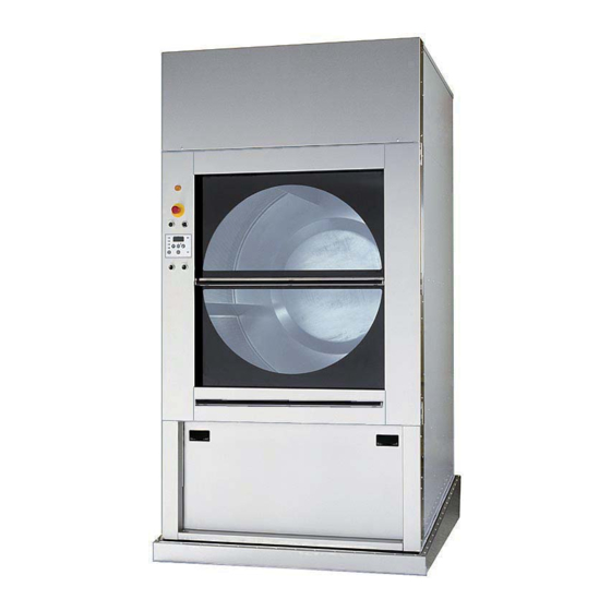
Service manual 3. Description of principal components Sliding Door and Tilt Operating panel Heating unit Indicator lamp Emergency stop Operating control panel Options- Sliding Door and tilt see the following page Loading door Drum Filter door / filter Tilt 487 03 29 41... -
Page 19: Operation Control Box/Panel
Service 3. Description of principal components manual Options Sliding Door and tilt buttons and symbols Indicator lamp for end of drying cycle ROTATION Knob for adjusting the Drum rotation while rotation speed of the emptying the dryer drum Operation control panel 487 19 24 03.02 Tilting the dryer. -
Page 20: Description Of Principal Components
Service manual 3. Description of principal components Sliding Door - Tilt 7° With tilt the dryer can tip forwards at 7°, fig. 1. Rotation of the drum The drum can be rotated with or without tilt and with the door open or closed. Gas reset button Fig.2 Open the control panel. -
Page 21: Motor
Service 3. Description of principal components manual Drum The drum is rear suspended in a bearing where the bearing housing is mounted in a cross beam mounted on the inner back plate. The drum is either made of stainless or galvanized steel. - Page 23 Service 11. Maintenance manual Contents Function check ..................11.3 Maintenance: Exhaust duct ................11.4 Nonreturn flap in evacuation pipe ..........11.4 Fan .................... 11.4 Door gasket ................11.4 Lint filter ..................11.5 Maintenance - Internal wearing parts: Cleaning around the drum ............11.6 Tightening belt ................
-
Page 25: Function Check
Service 11. Maintenance manual Function check Check that the drum is empty and the loading door is closed. Checking the micro switches Start the dryer. Check if the micro switches are working properly: • The dryer must stop if the loading door is opened. -
Page 26: Exhaust Duct
Service 11. Maintenance manual Maintenance Exhaust duct Check that the exhaust duct on the back of the dryer has not become blocked with lint or other debris (after three months, then every three to six months, as required). Nonreturn flap in evacuation pipe If the evacuation pipe has a nonreturn flap (2 dryers on a shared evacuation pipe), it must be cleaned at least once quarterly . -
Page 27: Lint Filter
Service 11. Maintenance manual Maintenance Lint filter Make a daily lint check. When maintaining the lint filter on a daily basis it does not have to be removed. Monthly, steam heated dryer Cleaning the filter in front of steam calorifer. 1. -
Page 28: Drum With Bearing
Service 11. Maintenance manual Maintenance - Internal wearing parts Maintenance should be conducted to an extent related to operation frequency and the conditions on the premises, or at least once a year. Remove all accumulated lint Cleaning around the drum 1. -
Page 29: Cleaning Around The Drum
11. Maintenance manual Maintenance Cleaning around the drum From serial no.: T3900/TD100 0401/000358 T31200/TD135 0401/000114 As from 1 January 2004 the design has been changed so that it is possible to clean around the support rollers without having to dismantle the front of the dryer. - Page 30 Service 11. Maintenance manual Cleaning around the drum. (continued from the previous page) 3. Service cover plates B, fig. 3. 4. Undo the 8 screws in each service cover plate (the screws must not be completely unscrewed), fig. 4. 5. Dismantle service cover plates B, fig. 5. 6.
-
Page 31: Tightening Belt
Service 11. Maintenance manual Tightening belt 1. Remove back plate. 2. Check that the spring is tightened as shown B Spring length A should be 45 mm ±1 mm, fig. 2. 3.Loosen the 4 bolts C holding the motor and mount the belt between the motor pulley and the idler 4. -
Page 32: The Area Surrounding The Dryer
Service 11. Maintenance manual The area surrounding the dryer Fresh-air intake to the room Check that the fresh-air intake to the room and the exhaust ducts/pipes from the room are not clogged by lint/dust or blocked in any other way. Dryer area Check that the dryer area is clear and free from combustible materials, gasoline and other... - Page 33 Service 21. Controls manual Contents Control locations: User module circuit board Standard door ..... 21.3 User module circuit board Sliding Door ..... . . 21.4 Control unit with main circuit board .
- Page 34 487 03 29 41...
- Page 35 Service 21. Controls manual Control locations Tumble dryer with standard loading door User module circuit board Fig. 1 The user module is placed in the operating box. The user module contains a circuit board with display, indicator lamps, a connector for the user keypad, and electronics to communicate commands to the main circuit board via a serial interface.
- Page 36 Service 21. Controls manual Warning! High voltage behind the screen Control locations Tumble dryer with Sliding Door Fig. 1 The user module is placed behind the panel. The user module circuit board contains display, indicator lamps, a connector for the user keypad, and electronics to communicate commands to the main circuit board via a serial interface.
-
Page 37: Control Unit With Main Circuit Board
Service 21. Controls manual Control unit with main circuit board Dryer with standard loading door Fig. 1 Control unit is placed behind the rear panel. Behind the back plate: Control unit with main circuit board and supply disconnector Internal control fuses, on electric heated dryers only Supply disconnector... - Page 38 Service 21. Controls manual Control unit with main circuit board Dryer with sliding door, tilt and frequency control Dryers with sliding doors can be controlled with up to 8 extra relays that govern tilt, drum rotation speed and frequency converter. KL KA KB KC KD KE KQ1 KQ Relays 110V AC: Indicator light / tilt (two-poles)
-
Page 39: Sliding Door Troubleshooting
Service 21. Controls manual Sliding Door Troubleshooting - Tilt If the tilt function does not work: 1. The input cable P to the control box K should give a reading of approximately 110V at 60 Hz or 220V at 50 Hz. •... - Page 40 Service 21. Controls manual Sliding Door Troubleshooting: No light on display D No light on display Power ON/ OFF Check S Make sure emergency stop main control is not switched off switch is ON or is loose Check line fuses Check F4 fuse on Process...
-
Page 41: Replacement Of Main Circuit Board
Service 21. Controls manual Replacement of main circuit board The main circuit board (Selecta Control) is not serviceable. It must be replaced if it fails. The main circuit board can be ordered as a spare part. The spare part consists of: Circuit board with fuses in anti-static packing and instructions. -
Page 42: Programming
Service 21. Controls manual Programming Sliding Door To enter the programming mode on the User Module: 1. Fig. 1 a Standard Door: Open the operating box. Fig. 1 b Sliding Door: Open the operating panel. 2. Fig. 1 Move the mode switch on the board into the position indicated by the arrow. - Page 43 Service 27. Sensors and overheating thermostats manual Contents Overview, inlet air:..........27.3 Overheating thermostat .
-
Page 45: Overview, Inlet Air
Service 27. Sensors and overheating thermostats manual Overview, Inlet air Positioning of sensors and overheating thermostats for inlet air. Fig. 1a+1b. Gas and Electric heating types have 1 overheating thermostat and thermistor element on the side of the heating calorifer. Fig. -
Page 46: Overheating Thermostat
Service 27. Sensors and overheating thermostats manual Inlet air - Overheating thermostat Function The inlet overheating thermostat opens automatically in the event of overheating, and shuts off the dryer. The thermostat opens and has to be reset manually. Resetting Electric heated dryers, fig. 1a+1b The overheating thermostats (2 pcs) are located behind the front shutter of the dryer, - one on side of the heating unit 1a and one just above the heating elements 1b. -
Page 47: Thermistor Element (Ntc Sensor)
Service 27. Sensors and overheating thermostats manual Inlet air - Thermistor element (NTC sensor) Function The thermistor element measures the temperature of the heated air entering the drum. The resistance of this device is normally 80 to 100 kOhms at 20°C and drops as the temperature increases. -
Page 48: Overview, Outlet Air
Service 27. Sensors and overheating thermostats manual Overview, Outlet air Positioning of sensors and overheating thermostats for outlet air. Fig. 1. Overheating thermostat and thermistor element, on electric, steam and gas heated dryers. On the following pages replacement and manual resetting are described. 487 03 29 41... -
Page 49: Overheating Thermostat
Service 27. Sensors and overheating thermostats manual Outlet air - Overheating thermostat Electric, gas and steam heated dryers Function The outlet air overheating thermostat is located on the outlet pipe at the back of the dryer. The overheating thermostat ensures that the dryer does not overheat during program operation. -
Page 50: Thermistor Element (Ntc Sensor)
Service 27. Sensors and overheating thermostats manual Outlet air - Thermistor element (NTC sensor) Function The sensor measures the temperature in the outlet air and the signal is returned to the main circuit board. The main circuit board turns the heating unit off when the outlet air thermistor indicates that the required temperature has been reached. -
Page 51: Vacuum Shutter And Switch
Service 27. Sensors and overheating thermostats manual Vacuum shutter and switch Active on electric and gas heated dryers only Function The vacuum switch ensures the necessary airflow in the dryer. Adjustment The switch must click when the distance from the vacuum shutter plate to the body of the dryer is approx. - Page 52 487 03 29 41...
- Page 53 Service manual 29. Door switch and filter switch Contents Standard door Loading door switch ........29.3 Testing door lock on loading door .
-
Page 55: Standard Door
Service manual 29. Door switch and filter switch Loading door switch Standard door A switch is mounted at the loading door hinge. The switch ensures that the dryer stops automatically if the loading door is opened during operation. If the dryer does not stop when the loading door is opened, the switch needs replacing. - Page 56 Service manual 29. Door switch and filter switch Testing door switch Standard door 1. Connect the power supply to the dryer. 2. Start the dryer. 3. Fig. 1 Check that the fan, drum rotation and heat all stop when the door is opened max.
-
Page 57: Testing Door Lock On Loading Door
Service manual 29. Door switch and filter switch Testing door lock on loading door Standard door It must be possible to open the door lock on the loading door from the inside with a force not exceeding 70N (7.138Kp). The door must be strained with a force corresponding to the above 70N (7.138Kp). -
Page 58: Lint Filter Switch
Service manual 29. Door switch and filter switch Lint filter switch, Standard door Function The lint filter switch ensures that the dryer will not operate when the filter door is open. If the dryer does not operate with the lint filter door closed and locked, the lint filter switch might need replacing. -
Page 59: Sliding Door
Service manual 29. Door switch and filter switch Loading door switch Sliding Door Two switches are installed at the loading door. Both switches are located in a box behind the control panel. The switches are connected in series, which ensures that the dryer stops automatically if the loading door or the panel is opened during operation. -
Page 60: Testing Door Switch On Loading Door
Service manual 29. Door switch and filter switch Testing door switch Sliding Door 1. Connect the power supply to the dryer. 2. Start the dryer. 3. Check that the blower, drum and burner stop when the door or panel is opened, fig. 1. If the loading door or panel can be opened without the dryer stopping, the switch(es) must be checked for defects (disconnect power,... -
Page 61: Lint Filter Switch
Service manual 29. Door switch and filter switch Lint filter switch, Sliding Door Function The lint filter switch ensures that the dryer will not operate when the filter door is open. If the dryer does not operate with the lint filter door closed and locked, the lint filter switch might need replacing. - Page 63 Service 30. Motor manual Contents Motor and transmission, general........30.3 Electric heating with internal fuses .
-
Page 65: Motor And Transmission, General
Service 30. Motor manual Motor and transmission, general Fan module. Fig. 1, A, Transmission module. Fig. 1, B. The dryer has two motors, one for the fan and one for the drum. Both motor types are protected by thermal overload relays C, fig. 2. If a motor overheats, the thermal overload relay is switched off and the control displays an error code. - Page 66 Service 30. Motor manual Internal fuses on electric Electric heating heated dryers Internal control On electric heated dryers the internal control is protected by internal fuses A located in fuse retainers B on the supply disconnector, fig. 1. Fuse sizes are in the table below, fig.
-
Page 67: Dismounting Fan Module
Service 30. Motor manual Dismounting fan module 1. Disconnect the power supply to the dryer. 2. Remove the back plate. 3. Fig. 1 Remove the 2 screws A from the bottom of the dryer. Loosen the 4 screws B. 4. Fig. 1. Disconnect the motor plug C. 5. -
Page 68: Replacements On Fan Module
Service 30. Motor manual Replacements on fan module Fig. 1 It is now possible to change the following: • Motor (a) • Fan wheel (b) Dismounting fan wheel / motor 1. Fig. 2. Unscrew screw A with washer. 2. Fig. 3. Pull the fan wheel off the motor ..shaft using a wheel dresser. -
Page 69: After Replacement
Service 30. Motor manual After replacements on fan module Finishing replacement 1. Assemble the dryer. 2. Connect the power supply to the dryer. Function check Check the dryer, see section 11: Function check 487 03 29 41... -
Page 70: Dismounting Transmission Module
Service 30. Motor manual Dismounting transmission module 1. Disconnect the power supply to the dryer. 2. Remove the back plate. 3. Fig. 1 Loosen the spring A by unscrewing screws B. 4. Disconnect the motor plug D, fig. 2. See next page. 487 03 29 41 487 03 29 41 487 03 29 41... - Page 71 Service 30. Motor manual Dismounting transmission module 5.Fig. 3 Remove screw E (the whole motor bridge then hangs from the belts C). 6. Dismount locking plate G in order to remove the motor bridge shaft F, fig. 4. 7.Lift the belts C off the pulleys and the whole transmission module with motor bridge can now be removed.
-
Page 72: Finishing Replacement
Service 30. Motor manual After replacement on transmission module Finishing replacement 1. Assemble the dryer (Tightening belts, see section 11: Function check). 2. Connect the power supply to the dryer. Function check Check the dryer, see section 11: Function check 487 03 29 41 487 03 29 41 487 03 29 41... - Page 73 Service 40. Heating system manual Contents Gas heated dryers: Description ..........40.3 Overheating thermostats .
-
Page 75: Gas Heated Dryers
Service 40. Heating system manual Gas heated dryers Description The gas burners (2 pcs) are located in the gas heating unit on the top of the dryer behind back plate A, fig. 1. The air is drawn through the louvres on the back plate and into the heating unit. -
Page 76: Gas Error
Service 40. Heating system manual Gas error Should a gas error occur error code E 14 will be displayed, fig. 1. In general gas errors occur due to supply shortage either if there is a gas failure or the gas pressure is too low. -
Page 77: Resetting Gas Error
5 times the size of the air outlet opening. To read more about the exhaust system see the installation manual for T31200 /T3900, TD135/ TD100. Resetting gas error (E 14) When resetting gas error E-14 the dryer must operate on a program with heat and the heat indicator must be on. - Page 78 Service 40. Heating system manual Replacing/adjusting gas burner/gas valve/ ignition electrode/flame sensor 1. Disconnect power to the dryer. 2. Dismount the top back plate A, fig. 1. 3. Remove the 6 screws B in order to dismount the 2 gas burners with valves and the control box , fig.
-
Page 79: Steam Heated Dryers
Service 40. Heating system manual Steam heated dryers Inlet Description Steam The steam calorifer A is located in the steam Return heating unit at the top of the dryer behind back plate A, fig. 1. The air is drawn through the louvres on the back plate and into the heating unit. -
Page 80: Replacing Actuator
Service 40. Heating system manual Replacing actuator Troubleshooting: • Voltage of screw terminals B must be 18V AC, fig. 1. • Damper must be adjusted correctly, wide open or shut. Dismounting actuator 1. Disconnect the power to the dryer. P10-6 P10-11 P10-5 2. - Page 81 Service 40. Heating system manual Replacing actuator continued Damper closed 7. See closed and open damper, fig. 4 and Actuator 8. Mount the wires in screw terminals B. Too long drying time The actuator on a steam calorifer pulls via a shaft a damper which opens/closes the air inlet to the drum.
-
Page 82: Electric Heated Dryers
Service 40. Heating system manual Electric heated dryers Description The electric heating unit is located on the top of the dryer behind back plate A, fig. 1. The air is drawn through the louvres on the back plate and into the heating unit. The heated air passes through the garments and the drum vents. -
Page 83: Electric Heating Unit Types
Service 40. Heating system manual Electric heating unit types Dryer type Voltage Heating Number of effect elements T3900/TD100 230 - 240V 50/60Hz 48 kW T3900/TD100 400 - 415V 50Hz 48 kW T3900/TD100 400 - 480V 60Hz 48 kW T3900/TD100/T31200/TD135 400 - 415V 50Hz... - Page 84 Service 40. Heating system manual Replacing electric heating element 1. Disconnect the power to the dryer. 2. Open front shutter, fig. 1. 3. Remove screws A from both sides of the heating unit, fig.2. 4. Remove the 2 bars B and the heating elements are now loose, fig.
- Page 85 Service manual 42. Drum with bearing Content Replacing supporting rollers, bearing or drum ....42.3 Replacing supporting rollers on dryers from 01.01.2004 ..42.10 Removing Sliding Door equipment .
- Page 87 42. Drum with bearing Replacing supporting rollers, bearings or drum To serial no.: T3900/TD100 0312/000357 T31200/TD135 0312/000113. The drum is rear suspended in a bearing where the bearing housing is mounted in a cross beam mounted on the inner back plate.
- Page 88 Service manual 42. Drum with bearing Replacing supporting rollers, bearing or drum (continued from the previous page) d) Open front shutter. e) Dismount service cover plates F, fig 4. Service cover plate for emergency stop socket, fig 5. f) Tip a screw driver under the loop G in order to dismount the emergency stop with wires.
- Page 89 Service manual 42. Drum with bearing Replacing supporting rollers, bearing or drum Continued on the following page h) Dismount 4 screws H at the bottom of the front plate, fig 8. i) Dismount 4 screws I at the top of the front plate, fig 9.
- Page 90 Service manual 42. Drum with bearing Replacing supporting rollers, bearing or drum (continued from the previous page) 3. Dismount back plate and remove the 2 V-belts J, fig 11. 4. Remove screws K in order to dismount the pulley. Mount one screw in hole L. The clamping sleeve is loosened when hole L is being used, fig 12.
- Page 91 Service manual 42. Drum with bearing Replacing supporting rollers, bearing or drum (continued from the previous page) 6. Pull the drum out carefully using a crane, a fork truck or another equipment, fig. 14. 7. Replacing bearing: a) Dismount defective bearing. b) Mount new bearing and mount the 4 nuts O without tightening them, fig.
- Page 92 Service manual 42. Drum with bearing Remount bearing and drum (continued from the previous page) 9. Remount in the opposite order. 10. Place drum carefully. Use Antifret paste or similar quality to lubricate the bearing surface. Note! After mounting the drum tighten the 4 nuts O in the bearing disc using 40 Nm.
- Page 93 Service manual 42. Drum with bearing 16. Mount front plate with door in the opposite order as the dismounting (see “Dismounting front plate” earlier in this section). Note! When mounting the emergency stop socket the loop G must face upwards, fig 21. 17.
-
Page 94: Service Cover Plates B, Fig
Service manual 42. Drum with bearing Replacing supporting rollers. From serial no.: T3900/TD100 0401/000358 T31200/TD135 0401/000114 As from 1 January 2004 the design has been altered so that support rollers can be replaced without having to dismantle the front of the dryer. -
Page 95: Connect The Power Supply
Service manual 42. Drum with bearing 6. Open the door, lift the drum and insert a wedge C between the front and the drum so that the support rollers are relieved of the pressure of the drum, fig. 5. 7. Dismount screw P with washer and bush and supporting rollers can be Dismounted/replaced. - Page 96 Service manual 42. Drum with bearing Sliding Door Replacing drum When removing / replacing the drum in a dryer with Sliding Door, all extra equipment for the Sliding Door must be dismantled. 1. Side screens in the filter compartment. 2. Left or right panel with microswitch. 3.
- Page 97 Service manual 42. Drum with bearing (continued from the previous page) Removing Sliding Door equipment: Recommended for removing the drum. • Disconnect the power to the dryer 1. Removing side screens P in filter compartment: 2. On the side panel with the door switch, remove rivets using a chisel or a drill.
- Page 98 Service manual 42. Drum with bearing Removing Sliding Door equipment: (continued from the previous page) 4. Carefully lower the doors onto the rubber buffers R. Take care! They weigh 24 kg. Dismantle the 2 cross members D by unscrewing the 3 screws E on either side and pull the members towards the clock: 5.
- Page 99 Service manual 42. Drum with bearing Removing Sliding Door equipment: (continued from the previous page) 6. Unscrew screw S in the bottom side panel. Unscrew the 3 screws in the top panel H. • Ties holding cables and wiring are untied or cut off, and the cable holders K are bent out so that the cable can be released.
- Page 100 Service manual 42. Drum with bearing Removing Sliding Door equipment: (continued from the previous page) 7. The top glass door is lifted up in the slide rails and secured to the front with lock grip pliers or clamps. 8. The bottom door can then be edged out of the slide rails by pressing gently to the right or left.
- Page 101 Service manual 42. Drum with bearing Removing Sliding Door equipment: (continued from the previous page) 9. Remove the top rivet in the side panel. The panel is then swung out at the top and secured with string as illustrated. 10. The slide rail Q is dismantled. Continued on the following page 487 03 29 41...
- Page 102 Service manual 42. Drum with bearing Removing Sliding Door equipment: (continued from the previous page) 11.The support rail T is dismantled. The front U is dismantled 12. After this, the procedures for dismantling and installing the drum are exactly the same as on a dryer with standard door, as described earlier in this section.
- Page 103 Service manual 43. Cabinet Content Sliding Door. Adjusting of sliding doors ..... 43.3 Sliding Door. Adjusting of wire rope, ..... . . 43.4 Sliding Door.
- Page 104 487 03 29 41...
- Page 105 Service manual 43. Cabinet Sliding Door. Adjustment of sliding doors It is important that the 2 sliding doors are parallel in order for the doors to close tightly, fig. 1. 1. Disconnect the power supply to the dryer. 2. Adjust a board to 555 mm for fixation of doors. •...
- Page 106 Service manual 43. Cabinet Sliding Door. (continued from the previous page) Adjusting of the wire rope 1. Check that the wire is tighten: • Loosen all 6 wire clamps A. • 2,5 kg wire traction must result in a motion of 100 mm as shown in figure 3.
- Page 107 Service manual 43. Cabinet Sliding Door. (continued from the previous page) Replacing of wire rope 1. Disconnect the power supply to the dryer. 2. Adjust a board to 555 mm for fixation of doors. • Place it between handle and girder B. 3.
- Page 108 Service manual 43. Cabinet Sliding Door Door gasket Check that the loading door gasket is clean and in good condition. Use a suitable cleaner. Do not use solvents that may damage sensitive plastics or painted finish. Check that felt packing A is intact and in good condition.
- Page 109 Service manual 43. Cabinet Sliding Door Locking plate and gas cylinder 1. The 2 sliding doors are kept closed by a locking plate A that engages in a guide bearing B when the 2 sliding doors are closed. The locking plate is held in position by a gas cylinder C that is installed on the reverse of the member, fig.
- Page 110 Service manual 43. Cabinet Sliding Door (continued from the previous page) Locking plate and gas cylinder 1. The cross member D is removed by pulling it towards the clock, fig. 1. 2. Gas cylinder C or locking plate A can now be replaced, fig.
- Page 111 Service manual 43. Cabinet Lifting capacity Dryer with tilting function must be min. 1 ton. If the tilting function fails in tilted position If the actuator fails while the dryer is in tilted position and the dryer is still to be used until the repairs have been carried out, it is necessary to get the dryer back in upright position.
- Page 112 Service manual 43. Cabinet Righting the dryer (continued) 3. Fig. 3 Position the lifting tackle. It is important to position the lifting tackle below the back bearer C so the centre of the lifting tackle supports the bearer. Before starting to lift the dryer ensure that the support under the lifting tackle is stable.
- Page 113 Service- manual 47. Gas System Contents Gas valve ..........47.3 Measuring, nozzle pressure .
-
Page 115: Gas Valve
Service- manual 47. Gas System Gas valve - Natural gas and LPG Pos. 1. Nozzle The nozzle orifice size must be correct for the installation altitude (US only) and the type of gas being used. Refer to the installation manual to determine proper orifice size. -
Page 116: Measuring, Nozzle Pressure
Service- manual 47. Gas System Measuring tap, nozzle pressure (pos. 2) 1. With the dryer off, loosen the gas pressure tap (pos. 2) one-quarter of a turn and connect a manometer to the tap. 2. Remove the ignition cable from the ignition electrode and position it so the end of the cable is at least 2 inches from any metal surface and away from any area into which you must reach to carry out this... -
Page 117: Measuring, Supply Pressure
Service- manual 47. Gas System Measuring tap, supply pressure (pos. 6) NOTE that the gas supply MUST be turned off before loosening tap pos. 6 (SUPPLY) or gas will escape. Refer to the installation manual for the proper supply pressure for the type of gas being used. -
Page 118: Test Run
Service- manual 47. Gas System Test run Test all joints for leaks. Before operating the dryer with a flame, check the supply and nozzle pressures as described earlier in this section. Check that the gas is burning evenly and with a bluish flame. - Page 119 Service manual 51. RMC (Residual moisture control) Contents RMC, general ......... . 51.3 Replacing the collector graphite .
- Page 121 Service manual 51. RMC (Residual moisture control) RMC, general The purpose of RMC is to be able to stop the dryer when a pre-selected moisture level has been reached in the clothes. Also see section 11, Dryer with RMC Replacing the collector graphite If the dryer stops almost straight away without the clothes being dry this is because the measuring system has been disconnected without a signal being sent to the control,...