Advertisement
Quick Links
Advertisement

Related Manuals for Olivetti ECR 8200


Summary of Contents for Olivetti ECR 8200
- Page 1 Cash Register ECR 8200 / 8220 SWEDEN SERVICE MANUAL Code Y110930 - 6 Service Manual...
- Page 2 PUBLICATION ISSUED BY: Olivetti S.p.A. 10015 Ivrea (Italy) Gruppo Telecom Italia Via Jervis, 77- 10015 Ivrea (ITALY) www.olivetti.com Copyright© 2009, Olive All rights reserved ATTENZIONE Pericolo d'esplosione se la batteria non viene sostituita in modo corretto. Sostituire solo con un tipo uguale o equivalente raccomandato dal costruttore.
- Page 3 PREFACE This Service Manual is addressed to the field engineers who will install and service the cash register. it also provides product maintenance guidelines. SUMMARY This manual Is divided into five chapters. The first two chapters describe the operating, functional checks and maintenance procedures. Chapter 3 describes the disassembly and reassembly procedures, Chapter 4 gives troubleshooting/repair information while Chapter 5 describes the electronic circuitry.
- Page 4 CONTENTS MAJOR FEATURES………………………………………………………………………………………... ECR 8200SV / 8220SV CASH REGISTER COMPONENTS…………………………………………… CASH REGISTER SPECIFICATIONS…………………………………………………………………… SAFETY PRECAUTIONS………………………………………………………………………………………………… MAINTAININING THE CASH REGISTER……………………………………………………………………………… UNPACKING AND SETTING UP THE CASH REGISTER…………………………………………….. STANDARD ACCESSORIES…………………………………………………………………………………………… THE KEYPAD FOR ECR 8200SV / 8220SV…………………………………………………………….. KEYPAD FUNCTIONS…………………………………………………………………………………………………… OPERATORE AND CUSTMER DISPLAY……………………………………………………………….. SWITCHING THE OPERATOR DISPLAY ON…………………………………………………………………………...
- Page 5 6. ASSEMBLY INSTRUCTION ......................6-1. TOP CASE UNIT ............................6-2. Display unit ASSY............................6-3. Bottom case unit ASSY ..........................7. CIRCUIT DIAGRAM ........................8. EXPLODED DIAGRAM ........................ Service Manual...
- Page 6 MAJOR FEATURES • 99 departments that can be grouped into up to 10 merchandise categories; • Up to 3,000 Price Look-Ups (PLU) with the possibility of associating a department and tax status to each; • 15 clerk numbers to monitor the sales of individual employees with programmable Clerk security system;...
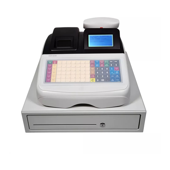
- Page 7 1.1 EXTERNAL COMPONENTS ECR 8200 SWEDEN External Components With reference to figure: 1. Customer display 2. Operator display 3. Keypad 4. Cash drawer and box 5. Cash drawer lock and slot 6. Item deposit drawer 7. Power cord 8. Storage Device (SD) – under printer compartement cover 9.
- Page 8 CleanCash(R) Box - Fiscal Control Unit The ECR 8200 cash register meets the requirements of Swedish legislation2007:592 which requires any business carrying out cash transactions in Sweden to use a certified cash register as of January 1st 2010. A certified cash register, as defined by the Swedish Tax Authorities, must have a Declaration of Conformity from the manufacturer and be connected to a certified fiscal control unit.
- Page 9 Electronic Funds Transfer Device An EFT device for validating credit card payments can be connected to either Serial port 1 or Serial port 2 on the cash register. For transactions paid by credit card, the customer is requested to enter their PIN number via the device. If validation is successful, two receipts are printed - one for the customer, the other for the business store.
- Page 10 CASH REGISTER SPECIFICATIONS Technical Characteristics Listed below are the technical characteristics of this cash register model. Type: Electronic cash register with clamshell thermal printer, 10 department groups, 99 departments, 15 clerks, up to 3,000 PLU settings. Max. 12,000-line Electronic Journal internal memory, expandable via memory storage device.
- Page 11 BCR Communication Parameters The BCR operates with either of these settings: Data length Parity Stop bit Baud rate PS700 default 9600 8 bits settings Metrologic MS5100 9600 7 bits Space Eclipse default settings Data Format: Bar code number (ASCII code) CR (0D<hex>) LF (0A<hex>) The ECR8220 can receive data scanned by the BCR in the data format above.
- Page 12 SAFETY PRECAUTIONS The power socket for this cash register must be located near the machine and must be easily Accessible. Do not use this cash register outdoors in the ram or near any liquid. MAINTAINING THE CASH REGISTER Provided below is information on how to maintain the cash register. Before cleaning the cash register, make sure it Is powered off and/or unplugged from the Note: wall outlet.
-
Page 13: Unpacking And Setting Up The Cash Register
UNPACKING AND SETTING UP THE CASH REGISTER STANDARD ACCESSORIES The cash register comes with the following items: • One black plastic journal winder spindle • One roll of standard paper tape • Three standard ‘AN’ size batteries for the battery back-up system •... - Page 14 THE KEYPAD FOR ECR 8200SV The figure below shows the keypad layout KEYPAD FUNCTIONS The keys described here are those by default on the cash register keyboard, shown in figure 5. configured The symbol (*) indicates that the key is also used in caption programming. NOTE: The keys can be reconfigured using the Free Key Layout option in “Advanced Settings”, if required.
- Page 15 -(*) Holds and then recalls a sales transaction so that a second transaction can be performed in the meantime. In caption programming, toggles between caps on/off to allow captions to be written in upper or lower case Ietters. (*) Transfers payment from one form of payment media to another after the sales transaction is finalized. (*)Pop-up Iist (5) allowing FC or TAKE-OUT sales operations to be performed.
- Page 16 18. -(*) Temporarily overrides a price that was assigned to a PLU number. During caption programming, when pressed before a character, sets the character as double width. 19. Pop-up list (4) allowing Paid Out (P0) or Received on Account (RA) transactions. As the P0 key register any money taken out of the cash drawer that is not part of a sale.
-
Page 17: Keypad Functions
THE KEYPAD FOR ECR 8220SV The figure below shows the keypad layout KEYPAD FUNCTIONS The keys described here are those by default on the cash register keyboard, shown in figure 5. configured The symbol (*) indicates that the key is also used in caption programming. NOTE: The keys can be reconfigured using the Free Key Layout option in “Advanced Settings”, if required. - Page 18 , enter the PLU code. Temporarily overrides a price that was assigned to a PLU number Price look-up function. Registers the preset price of an individual item to the appropriate department. When programming PLUs, to display a given PLU, enter its number then press this key. Enters the number of guests at a determinate table.
- Page 19 options and form In Programming mode, these keys can be used to move through the menu fields in the direction indicated on the key. When the menu item required is highlighted, press to select it. When navigating forms, if line numbers are present on the left, jump to the line you want by entering its number followed by either arrow key.
- Page 20 Clears an entry made from the numeric keypad or with before finalizing a transaction with a Department or function key. Also used to clear error conditions. In Off mode, activates the menu for resetting the cash register. When operated outside of a sales transaction, displays setup information: the current date and time, clerk number, Electronic Journal status and number of free EJ lines.
-
Page 21: Clearing An Error
These functions respectively can be used to select PLU codes in the ranges 1- 35, 201-235 and 301 – 305. The PLU codes you want to use must previously have been programmed. To enter a PLU codeassociated with a PLU Page, first press the PLU Page key, then press the key for the PLU code. Note: The PLUranges associated with the PLU Pages can be modified. - Page 22 OPERATOR AND CUSTOMER DISPLAYS The operator LCD display has a Menu system providing access to all cash register functions. You can raise and tilt the display to obtain the most comfortable viewing position. The pop-up, single-line, customer display can be raised and swivelled to obtain the most favorable position for customer viewing. When sales transaction data is not displayed, scrolling messages can be programmed to appear according to the cash register state (idle, off and so on).
- Page 23 PROGRAMMING MODE – Operator Display REGISTRATION MODE ( 2 ) Training mode ( 4 ) Hold mode - A transaction has been temporarily put on hold. ( 4 ) RecalI mode - A transaction on Hold has been recalled for completion. EJ nearly –...
- Page 24 REGISTRATION MODE lndicates amounts entered and sales totals, max. 8-digits (no.) (right -- side CD). Indicates that a Take-out tax rate is applied to the transaction. ( 4 ) Indicates that a Business Receipt has been requested. ( 2 ) PLU Page 2 ( 2 ) PLU Page 3...
- Page 25 PRINTER COMPARTMENT The printer compartment Is on the top Ieft-hand side of the cash register. It houses the thermal paper roll, journal winder spindle, back-up batteries and the thermal printer. This cash register uses standard 21/4” (57 mm) thermal paper. LOADING THERMAL PAPER FOR ECR 8200SV / ECR 8220SV MODELS Proceed as follows to Ioad the cash register with paper.
- Page 26 6. Lower the clamshell mechanism and secure it in place by pushing it all the way down until it clicks into pace. 7. Replace journal winder with wheel to right of compartment. 8. Pass the edge of the customer receipt through the receipt window on the compartment cover.
- Page 27 Set the menu RECEIPT MODE switch to JOURNAL, press the [Feed] key and manually feed the paper into the slot until the paper catches and advances approximately six to ten inches above the print mechanism. Note: I the paper does not feed properly, check the alignment of the paper in the slot and/or for the straight edge on the end on the paper roll.
- Page 28 1-3. KEYBOARD <ECR8200/SWEDEN> The keyboard consists of Stroke 42 keys with key caps (except numeric keys). Numeric keys Department keys and letters for Amount tender key programming Service Manual...
- Page 29 <ECR8220/SWEDEN> The keyboard consists of Flat 90 keys. PLU keys and letters for programming Numeric keys Amount tender Service Manual...
- Page 30 1-4. DRAWER The drawer type is DSCA, 4 Bill / 8 Coin with D/DRAWER. D/Drawer 4 Bill tray 8Coin tray Service Manual...
- Page 31 1-5. PRINTER The printer is SII LTPC-235, that is a line thermal printer developed for ECR use. 58mm 1 Station Thermal Printer. 1-6. INTERFACE RJ45 x 3 for Fiscal Box, Barcode Reader, PC, and EFT. RJ45 x 3 for Fiscal Box, SD Memory Barcode Reader, card slot...
- Page 32 1-7 SYSTEM BLOCK DIAGRAM Printer Rear Display Display Motor Control 10digits 16segment VFD Control LTPC235 Main CPU Front Display M30842MC 160 x 80 dots LCD Key scans Print Control Return Keyboard Wind Motor Buzzer 9.83 MHz Drawer Main Clock X’TAL Sol.
- Page 33 2. TROUBLE SHOOTING GUIDANCE In the event following abnormal symptom happened, refer to the solution corresponding to its symptom. Symptom Check point / Detailed symptom Page No Power. Check the Power supply circuit. - - - Try STEP 1&2 P.11 If Power supply circuit is OK, check RESET circuit.
- Page 34 3. CIRCUITRY 3-1 POWER SUPPLY CIRCUIT +VDRW +VDRW is generated using the AC input across pins 3 of CN12. This AC voltage is rectified by D15, a 1SR154 diode. The resulting DC voltage is about +24V. This voltage is used by the drawer solenoid and the buzzer.
- Page 35 POWER SUPPLY CIRCUIT continued VDRW VDRW 1SR154-400 R102 EC18 R199 470uF_50V EAM-2967 2SA1036K VPRN VPRN (+7.6V) 2SD1415A R136 R169 4.7K 2.2K EC11 R140 100uF_16V DTC143EKA HVPSW 0.1uF RD9.1EB2 TR-5 19370 1.6A VCC3 VCC3 R131 EC31 EC12 R186 100uF_ 0_1W(6432size) R177 Vin1 Vin1 TR-5 19370 1.6A...
- Page 36 3-2. TRANSFORMER WIRING DIAGRAM Primary Fuse CT-89E AC250V T500 mAL AC13V / 2A AC24V Input Voltage AC26.7V AC230V 50Hz AC4.8V Trouble shooting - Check the Continuity at Primary FUSE. If it’s OPEN. - - - Replace Fuse. After replacing FUSE but it opens again.- - - Check Power Supply circuit. (P.9, 10) - Check the Thermal Fuse.
- Page 37 3-3. M30842MC MICROCOMPUTER Refer to the specification (attached). Service Manual...
- Page 38 Port Assignment for ECR8200/8220 SWEDEN (M30842MC) Service Manual...
- Page 39 Service Manual...
- Page 40 3-4. RESET CIRCUIT The reset circuit prevents the CPU from starting to operate before the system is fully powered-up and initialized. Then 29m sec. after power is applied, reset goes high and the CPU can begin functioning. When power is first applied to the circuit, the VBB begins charging C141 a capacitor. Output of Reset IC(U10) is low-resistance at VBB-Line is less than 3.0 Volts.
- Page 41 3-5. POWER FAIL CIRCUIT Power fail generated by a circuit using the PF DTC voltage. When power is on and the system is operating normally, the power fall signal stays at a higher voltage than 1.21V. The CPU watches power failure signals all the time. When power is on, PF -5pin at High level. When power down and CPU(U1)27pin voltage goes down lower than PF detection voltage(=1.21V), low-power-supply detector circuit of the CPU works and execute PF.
- Page 42 Trouble shooting - Start up the Diagnostic software and check whether winding motor is properly working or not. - - -See 4. DIAGNOSTIC SOFTWARE CHECK - If Winding motor does not work, start up Diagnostic software again and check the following voltage when the test report is printing on a receipt. Note) When a printer is not working, the power supply of the winding motor should be OFF status / 0V.
- Page 43 3-7. DISPLAY CIRCUIT VCC5 0(3216) *C114 EC10 1000uF_16V 0.1uF 0(3216) CN11 VCC3 0.1uF LC_CD# LC_RD# 0.1uF LC_RST# LC_WR# LC_D0 LC_D1 LCD Module LC_D2 LC_D3 LC_D4 LC_D5 LC_D6 LC_D7 LC_CE# LC_LEDA SN74LV245APWR C03-20AG1 10 x 2 (MALE) 0.1uF 10x2 Box-Header(P=2.54mm) VCC3 0.1uF LCD_RST# LCD_CS#...
- Page 44 VCC5 VCC5 VCC5 -Vpw C142 1000pF 0(3216) C143 1000pF R139 CS0# R_VFD -VPW B8B-PH-K-S C129 *0.1uF EC17 *100uF_50V 10uF_16V 0(3216) VCC5 0.1uF nDATA nDATA HCLK HCLK HLATCH# HLATCH# VFD_CS0# VFD_CS0# STB2# STB2# STB1# STB1# VFD_TXD VFD_TXD VFD_CLK VFD_CLK TC74VHCT244FT Trouble shooting - Check the power supply of Display tube.
- Page 45 3-8. DISPLAY INFORMATION Front Display LCD (160 x 80 dots) Part No.: GY1608A8SKY6T Refer to the specification (attached). Rear Display VFD (16 segments) Part No.: 10LY-01G Segment j k b e r p n . (Union Jack) Character size : 14 mm (H) x 4.9 mm (W) Service Manual...
- Page 46 3-9. KEYBOARD CIRCUIT Keyboard Scan lines are the CPU ports, these CPU ports are P120-126 and P130-137. Keyboard Return lines are the CPU ports, these CPU ports are P140-145. It is consist of matrix of Scan line (11) × Return line (5). <8200/SWEDEN>...
- Page 47 <8220/SWEDEN> It is consist of matrix of Scan line (15) × Return line (6). KEY MATRIX RETURN0 RETURN1 RETURN2 RETURN3 RETURN4 KEY SCAN RETURN5 SCAN1 SCAN2 SCAN3 SCAN4 Connector10 SCAN5 SCAN6 SCAN7 SCAN8 SCAN9 SCAN10 SCAN11 SCAN12 SCAN13 SCAN14 SCAN15 Connector11 RETURN5 RETURN4...
- Page 48 3-10. DRAWER CIRCUIT The solenoid for a drawer is activated using the signal P110 from the CPU. This signal is normally Low, and goes High to cause the drawer to run. When P110 is High, Q2 is on. Current flow through the transistor cause the collector to be held Low, near grand potential. VDRW 1S R154 -400 B3 P-SHF-1A A...
- Page 49 3-11. BUZZER CIRCUIT The buzzer circuit uses as its input signal P74 from the CPU. This normally Low signal and goes High on 2 conditions. First on an error tone, P74 goes Clocked until the error condition is cleared. For a key beep tone, P74 goes High and then returns to its Low state. This pulse is of extremely short duration.
- Page 50 3-12. BATTERY CIRCUIT VBB voltage is used by CPU, external RAM and FROM. It is supplied by dry battery at the time of back-up. Battery specification Type : AA x 3pcs Voltage: 4.5V CAUTION; RISK OF EXPLOSION IF BATTERY IS REPLACED BY AN INCORRECT TYPE. DISPOSE OF USED BATTERIES ACCORDING TO THE INSTRUCTIONS.
- Page 51 Service Manual...
- Page 52 3-13. EXTERNAL MEMORY 3-13-1. SRAM (BS62LV4006SCP-70) 512K bytes S-RAM used as an external RAM for PLU and Electric Journal and etc. P00 through P07 are multiplex bus that consists of data bus (D0-D7). P20 through P27 are multiplex bus that consists of data bus (A0-A7). P30 through P37 are multiplex bus that consists of data bus (A8-A15).
- Page 53 S-RAM PIN Configuration Refer to the specification. (attached data sheet) Service Manual...
- Page 54 3-13-2. FROM (S29AL004D70TFI010) *May be changed later. 512K bytes FROM is used as programming. P00 through P07 are multiplex bus that consists of data bus (D0-D7). P20 through P27 are multiplex bus that consists of data bus (A0-A7). P30 through P37 are multiplex bus that consists of data bus (A8-A15). P40 is multiplex bus that consists of data bus (A16).
- Page 55 FROM PIN Configuration Refer to the specification. (attached data sheet) *To be changed later. (To be Announced) Service Manual...
- Page 56 Service Manual...
- Page 57 3-14. PRINTER CIRCUIT Thermal Head The thermal head of the printer consists of heat elements, and head drivers to drive the heat elements. Serial printing data input from the DAT IN pin is transferred to the shift register synchronously with the CLK signal, then stored in the latch register with the timing of the LATCH signal.
- Page 58 Motor and Thermal Head drive timing Figure 3-14-2. 2-Division Printing Timing Chart Service Manual...
- Page 59 PRINTER CIRCUIT VPRN R121 SHVP 15K_F R132 5.1K_F *470pF VCC5 VCC5 0.1uF nDATA R122 DAT_IN VCC5 nDATA HCLK R123 HCLK 1000uF_16V HLATCH# R124 LATCH# HLATCH# VFD_CS0# VFD_CS0# STB2# R125 P_DST2# STB2# STB1# R126 P_DST1# STB1# VFD_TXD VFD_TXD VFD_CLK VCC5 VFD_CLK 0.1uF R133 TC74VHCT244FT...
- Page 60 3-15. INTERFACE CIRCUIT RJ45 I/F COM A : IF SEL, TXD1, RTS#1, B_CTS1# and B_RXD1# are UART communication parts from the CPU. U17(MAX3232CPWR) is RS232C transceiver. COM A is used for PC or Barcode or EFT. COM B : TXD2, RTS2#, RXD2 and CTS2# are UART communication parts from the CPU. U7(MAX3232CPWR) is RS232C transceiver.
- Page 61 Trouble shooting - COM A, B or C does not work when power ON. Check the voltage (AC +5.0V) at point (1) on page 11. If it outputs properly - - - Replace the Harness ass’y. If it doesn’t output properly - - - Replace the Main board. - Cannot write or read the data for SD card Check the voltage (DC +3.0V) at point (A).
- Page 62 4. DIAGNOSTIC SOFTWARE 4-1. DIAGNOSTIC CHECK & FINISHED GOODS CHECK Diagnostic Software will check whether the machine works properly or not. It is already built in the machine and is always ready to boot this software by the following instructions. It is also useful to check after repairing the machine.
- Page 63 Service Manual...
- Page 64 Service Manual...
- Page 65 Service Manual...
- Page 66 <ECR8220 SWEDEN> Service Manual...
- Page 67 Service Manual...
- Page 68 Service Manual...
- Page 69 It means OK when no error occurs through the checkup. Service Manual...
- Page 70 FINISHED GOODS CHECK LIST <ECR8200 SWEDEN> Service Manual...
- Page 71 Service Manual...
- Page 72 Service Manual...
- Page 73 Service Manual...
- Page 74 <ECR8220 SWEDEN> Service Manual...
- Page 75 Service Manual...
- Page 76 Service Manual...
- Page 77 Service Manual...
- Page 78 4-2. SOFTWARE VERSION CHECK Through the diagnostic check, it shows the software version in the beginning of the check. However, it is possible to check only the software version without diagnostic check. SOFTWARE VERSION CHECK 1) Input [960801] at the system initialization. 2) VFD (Customer display) will show you the current software version.
- Page 79 Appendix : jig for RS232C PORT Testing jig = Loop back connector for barcode scanner <Connecting Diagram> RJ45 8 pin 1kΩ D-sub 9 pin 1kΩ Service Manual...
- Page 80 5. INSTALLING SOFTWARE 5-1. SOFTWARE LOADER install In order to install software, start up “M32CPU series ECR_LOADER”. The down load is available via the USB interface. Before doing the following procedure, the PC has to install the USB-COM driver referring to “6 USB driver install”. Please follow the instruction below in numeric order.
- Page 81 3) Check COM Port number. Note)If you use usb-com conversion, there might be shown “USB Serial Port (COMn)”. After you checked the COM Port number, please close the “device manager”. 4) Execute Up_Loader. You can find the icon as shown. Service Manual...
- Page 82 5) Set the COM Port number using [Com set] button. Set the COM Port number which you checked at 3). Click [OK]. ECR side 6) Unplug the power and remove the battery. 7) Connect the cable to PC. PC side 8) Click [OK].
- Page 83 9) Click [Boot] button. 10) Up_Loader is waiting for the ECR start-up. ECR side 11) Turn on the power with depressing [1] and [9] of ten key together. When the connection (to PC) is confirmed, it beeps twice. (“Pi Pi”) 12) If it doesn’t perform properly at this stage, ECR side might have started up the LOADER already.
- Page 84 PC side 13) When it’s connected to ECR, it shows [Boot OK]. Click [EEPROM Erase] button. 14) When it successfully done the deletion, it shows [OK]. Service Manual...
- Page 85 15) Click [UP LOAD] button. Select the file you wish to download. Click [Open]. 16) It shows a status for transmitting. Service Manual...
- Page 86 17) It shows [Up Load OK] 18) Click [Ver] button. Service Manual...
- Page 87 19) It shows the version which was transmitted. 20) Click [RUN] button. ECR will be started-up by the software loaded just now. Now that the machine has installed new software, it is required to check its functions are properly installed or not. Please go back to section 3, “DIAGNOSTIC SOFTWARE” to check the machine. Service Manual...
- Page 88 6. ASSEMBLY INSTRUCTION 6-1. TOP CASE UNIT <ECR8200 SWEDEN> (1) FIX KEY TOP SHEET TO KEY KEY CAP [1X1] RUNNER GATE POSITION CAP THEN FIX TO BASE TOP ON TOP SIDE KEY. KEY CAP [1X2] RUNNER GATE POSITION ON LEFT SIDE KEY TOP SHEET BASE TOP KEY (2) FIX K/B PWB UNIT TO KEY...
- Page 89 <ECR8220 SWEDEN> (1) FIX RUBBER SHEET TO KEY KEY FRAMEKEY FRAME WITH FLAT. IT MUST BE ON FITTING BOSSES POSITION. RUBBER (2) FIX K/B PWB UNIT TO KEY FRAME WITH FLAT. IT MUST BE ON FITTING BOSSES POSITION THEN FASTENING 12PCS SCREW.
- Page 90 <ECR8200/8220 SWEDEN> TTOP CASE 1] FIX 2PCS PAPER ROLLER TO TOP CASE. [AS SHOWN ON THE UPPER PICTURE ] 2] SLOT MOTOR SET PIECE TO PAPER ROLLER TOP CASE. [AS SHOWN ON THE BELOW PICTURE ] MOTOR SET PEACEECE (4) FIX 2PCS BATTERY CONTACT TOP CASE TO TOP CASE.
- Page 91 <ECR8200 SWEDEN> (5) FIX KEY FRAME TO TOP CASE PRESS UNTIL IS LOCKED. (6) FASTENING 6PCS SCREW, TOP CASE KEY FRAME TO TOP CASE. SCREW KEY TOP Service Manual...
- Page 92 <ECR8220 SWEDEN> (5) FIX KEY FRAME TO TOP CASE PRESS UNTIL IS LOCKED. (6) FASTENING 6PCS SCREW, KEY FRAME TO TOP CASE. TOP CASE SCREW KEY FRAME Service Manual...
- Page 93 <ECR8200/8220 SWEDEN> LCD COVER 1]APPEARANCE CHECK COVER. 2] FIX LCD COVER TO TOP CASE. [AS SHOWN ON PICTURE.] TOP CASE Service Manual...
- Page 94 (8) FIX LCD COVER TO TOP CASE BY FASTENING 4PCS SCREW. SCREW (9) FIX 2PCS PLATEN SPRING TO PLATEN ARM THEN FIX TO TOP PLATEN ARM CASE. PLATEN SPRING Service Manual...
- Page 95 (10) FIX LCD MODULE UNIT TO LCD MODULE UNIT TOP CASE. NOTE: The display unit is described in the next section (6-2). CABLE SLOT HERE Service Manual...
- Page 96 (11) 1] FIX R/DISPLAY UNIT TO TOP R/DISPLAY UNIT CASE. 2] CHECK AND CLEAN REMOTE FILTER AND DISPLAY TUBE BY USE METHANOL. 3] FIX REMOTE FILTER TO R/DISPLAY CASE. [AS SHOWN ON PICTURE.] REMOTE FILTER AMOU Service Manual...
- Page 97 (12) 1]CLIP FERRITE CLAMP TO HARNESS ASSY THEN TURN ONE ROUND TO FERRITE 30mm 2] CLIP HARNESS ASSY TO CORD CLAMP. [AS SHOWN ON FERRITE CLAMP PICTURE.] [1 TURN] CLIP HARNESS ASSY IN THIS CORD TOP CASE UNIT Service Manual...
- Page 98 6-2. Display unit ASSY (1) INSERT HARNESS ASSY LCD MODULE UNIT. LCD MIRROR NON-GLARE SURFACE (TAK SILAU) HARNESS ASSY LCD MODULE UNIT SOLDER LED (2) SOLDER HARNESS ASSY TO LCD MODULE UNIT. LCD MODULE UNIT Service Manual...
- Page 99 1] SLOT LCD MODULE HARNESS ASSY TO LCD REAR CASE. 2] FIX LCD MODULE TO LCD REAR CASE. LCD REAR CASE 3] FIX LCD FRONT CASE TO LCD REAR CASE AND PREES UNTIL IS LOCKED. LCD MODULE FRONT Service Manual...
- Page 100 (4) CLIP FERRITE CLAMP TO HARNESS ASSY AND TURN ONE ROUND TO FERRITE CLAMP. HARNESS ASSY FERRITE CLAMP [1 TURN] 30mm Service Manual...
- Page 101 6-3. Bottom case unit ASSY 1] APPEARANCE CHECK THE BOTTOM CASE BOTTOM CASE. 2] STICK CORD CLAMP TO BOTTOM CASE. [LOCATION AS SHOWN ON PICTURE.] TAB SIDE CORD CLAMP Service Manual...
- Page 102 1] SLOT HARNESS ASSY TO BOTTOM CASE. [FOLLOW THE HARNESS ASSY SLOT HERE PICTURE AS SHOWN ON FIGURE.] 2] TIE TOGETHER HARNESS ASSY WITH BOTTOM CASE BY USE INSULOCK TIE. SHOWN ON PICTURE.] HARNESS ASSY [CA24-903A] BOTTOM CASE INSULOCK TIE 130mm Service Manual...
- Page 103 (3) FIX TRANSFORMER UNIT TO DRAWER UNIT BY FASTENING 2PCS SCREW. AC CORD SLOT HERE SCREW Service Manual...
- Page 104 1] FIX AC CORD TO BOTTOM CASE. AC CORD PUT LIKE THIS 2] FIX INLET SET PIECE TO BOTTOM CASE BY FASTEN 2PCS SCREW. [AS SHOWN ON PICTURE] BOTTOM CASE INLET SET PIECE SCREW Service Manual...
- Page 105 BOTTOM 1] FIX FUSE HOLDER PWB TO PICTURE 1 CASE BOTTOM CASE BY FASTENING 1PC SCREW. [AS ON PICTURE 1.] 2] SLOT FUSE TO FUSE HOLDER. [AS ON PICTURE 2.] 3] FIX FUSE CAP TO FUSE HOLDER. [AS ON PICTURE 3.] SCREW FUSE PICTURE 2...
- Page 106 1] INSERT DRAWER CONNECTOR AND TRANSFORMER CONNECTOR TO MAIN PWB UNIT. [AS ON PICTURE ] MAIN PWB 2] INSERT USB JUMPER LEAD AND I/F/PLATE CABLE TO MAIN PWB. TRANSFORMER DRAWER HARNESS HARNESSINSER INSERT TO [CN12] T TO [CN5] I/F PWB CABLE [6pin] INSERT TO [CN10] I/F PWB CABLE [5pin] I/F PWB CABLE [5pin]...
- Page 107 (9) INSERT DISPLAY HARNESS, BATTERY BOX HARNESS AND PRINTER PWB JUMPER LEAD TO MAIN PWB. [LOCATION AS SHOWN ON PICTURE.] FIRST PIN PRINTER PWB JUMPER PRINTER PWB LEAD JUMPER LEAD [13pin] INSERT TO [CN7] [9pin] INSERT TO [CN6] FRONT DISPLAY HARNESS INSERT TO [CN9] BATTERY BOX...
- Page 108 (10) INSERT LCD MODULE HARNESS, SD CARD HARNESS AND K/B JUMPER LEAD TO MAIN PWB. [LOCATION AS SHOWN ON PICTURE.] FRONT DISPLAY HARNESS INSER BATTERY BOX HARNESS T TO [CN13] SD CARD CABLE INSERT TO [CN2] FIRST PIN K/B JUMPER LEAD INSERT TO [CN1] [10pin] K/B JUMPER LEAD...
- Page 109 <ECR8200 SWEDEN> (11) FIX SEMI SET TO BOTTOM CASE SEMI SET Service Manual...
- Page 110 <ECR8220 SWEDEN> (11) FIX SEMI SET TO BOTTOM CASE SEMI SET (11) PICTURE 1 1] FIX FLAT RUBBER TO TOP CASE. [AS PICTURE 1] 2] FIX 2PCS FLAT KEY SHEET AT FLAT RUBBER FLAT RUBBER. [AS PICTURE 2] 3] FIX SILICON RUBBER TO TOP CASE.
- Page 111 <ECR8200/8220 SWEDEN> (12) FASTEN 2PCS SCREW, TOP CASE TO BOTTOM CASE. SCREW (13) FIX KEY FRAME TO TOP CASE PRESS UNTIL IS LOCKED. DEPOSIT Service Manual...
- Page 112 (14) COPLETE AND FUNCTION BATTERY TEST. WINDING REEL ASSY UNIT Service Manual...
- Page 113 7. CIRCUIT DIAGRAM IF_SEL IF_SEL VFD_TXD VFD_TXD VFD_CLK VFD_CLK VFD_CS0# VFD_CS0# D[0..7] D[0..7] R145 *10K R_HDUP R_HDUP R146 *10K R_PEND R_PEND R147 *10K + EC4 R_SHTH 10uF_16V R_SHTH R148 *10K SHVP SHVP D15/A-1 0.1uF *0.01uF 10uF_16V 10uF_16V 0.1uF RXD1 RXD1 TXD1 TXD1 CTS1#...
- Page 114 VCC5 VCC5 VCC5 -Vpw C142 1000pF 0(3216) C143 1000pF R139 CS0# R_VFD -VPW B8B-PH-K-S C129 *0.1uF EC17 *100uF_50V 10uF_16V 0(3216) VPRN R121 SHVP 15K_F R132 VDRW 5.1K_F *470pF VCC5 VCC5 1SR154-400 Drawer 0.1uF B3P-SHF-1AA nDATA R122 DAT_IN VCC5 nDATA HCLK R123 HCLK R105...
- Page 115 VCC3 VCC3 VMEM HAT1089C-EL-E KEY RTN0# KEY RTN1# KEY RTN2# 100k KEY RTN3# 100uF_16V KEY RTN4# KEY RTN5# KSCAN0# KEY BOARD1 KSCAN1# KSCAN2# KR[0..5] KR[0..5] KSCAN3# 52147-1010 VMEM VMEM VSD_EN VCC3 0.1uF SD_CS# SD_DO KSCAN4# SD_CK SD CARD I/F KSCAN5# KSCAN6# SD_DI KSCAN7#...
- Page 116 VCC5 0(3216) *C114 VCC3 EC10 + EC5 100uF_16V 1000uF_16V 0.1uF 0(3216) CN11 VCC3 0.1uF LC_CD# D[0..7] LC_RD# D[0..7] 0.1uF LC_RST# LC_WR# LC_D0 LC_D1 LCD Module LC_D2 LC_D3 LC_D4 LC_D5 LC_D6 LC_D7 LC_CE# LC_LEDA SN74LV245APWR C03-20AG1 10 x 2 (MALE) 0.1uF 10x2 Box-Header(P=2.54mm) VCC3 0.1uF...
- Page 117 VDRW VDRW 1SR154-400 R102 Vin1 VCC5 VCC3 EC18 R199 470uF_50V C134 R170 R172 4.7K_F 2SA1036K EAM-2967 *3.9K_F VCC3 VPRN 0.1uF VPRN (+7.6V) 2SD1415A R106 4.7K R171 C133 R136 R169 4.7K 2.2K 1.5K_F 0.1uF M51957BFP R173 EC11 R140 C135 *47K *1000pF 100uF_16V Power Fai l DTC143EKA...
- Page 118 P2.0mm*10pin KEY RTN0 KEY RTN1 KEY RTN2 KEY RTN3 KEY RTN4 KEY SCN0 KEY SCN1 KEY SCN2 KEY SCN3 KEY SCN4 KEY SCN5 KEY SCN6 KEY SCN7 KEY SCN8 KEY SCN9 KEY SCN10 P2.0mm*11pin KEY RTN4 KEY RTN3 KEY RTN2 KEY RTN1 KEY RTN0 KEY LAYOUT...
- Page 119 RETURN0 RETURN1 RETURN2 RETURN3 RETURN4 KEY SCAN RETURN5 SCAN1 SCAN2 SCAN3 SCAN4 Connector10 SCAN5 SCAN6 SCAN7 SCAN8 SCAN9 SCAN10 SCAN11 SCAN12 SCAN13 SCAN14 SCAN15 Connector11 RETURN5 RETURN4 RETURN3 KEY RETURN RETURN2 RETURN1 RETURN0 TITLE. DRAWING No. ECR8220/ 8220 SWEDEN EBC-1020 FLAT Keyboard DESINR.
- Page 120 B8B-PH-K-S Main Board 100k 1N4148 RESET# + EC1 *S-80845ANY 1uF/50V 0.1uF 10uF/16V 100kx6 0.1uF 22pF 1000pF 1000pF 1000pF SEG0 SOUT SEG1 SCLK SEG2 SEG3 -Vpw SEG4 DIG0 SEG5 DIG1 SEG6 DIG2 SEG7 DIG3 SEG8 DIG4 SEG9 PT6355 10-LY-01G * Mark not used. TITLE.
- Page 121 8. EXPLODED DIAGRAM <ECR8200/SWEDEN> Service Manual...
- Page 122 <ECR8220/SWEDEN> - 97 - Service Manual...