Table of Contents
Advertisement
Quick Links
Advertisement
Table of Contents

Related Manuals for Acer PREDATOR G5900


Summary of Contents for Acer PREDATOR G5900
- Page 1 Acer Predator G5900 Service Guide PRINTED IN TAIWAN...
-
Page 2: Revision History
Revision History Please refer to the table below for the updates made on this service guide. Date Chapter Updates... - Page 3 Copyright Copyright © 2010 by Acer Incorporated. All rights reserved. No part of this publication may be reproduced, transmitted, transcribed, stored in a retrieval system, or translated into any language or computer language, in any form or by any means, electronic, mechanical, magnetic, optical, chemical, manual or otherwise, without...
- Page 4 Any Acer Incorporated software described in this manual is sold or licensed "as is". Should the programs prove defective following their purchase, the buyer (and not Acer Incorporated, its distributor, or its dealer) assumes the entire cost of all necessary servicing, repair, and any incidental or consequential damages resulting from any defect in the software.
- Page 5 Conventions The following conventions are used in this manual: SCREEN MESSAGES NOTE WARNING CAUTION IMPORTANT Denotes actual messages that appear on screen. Gives additional information related to the current topic. Alerts you to any physical risk or system damage that might result from doing or not doing specific actions.
-
Page 6: Fru Information
Service Guide. For ACER-AUTHORIZED SERVICE PROVIDERS, your Acer office may have a DIFFERENT part number code to those given in the FRU list of this printed Service Guide. You MUST use the list provided by your regional Acer office to order FRU parts for repair and service of customer machines. -
Page 7: Table Of Contents
Table of Contents System Tour Features Block Diagram System Components Front Panel Rear Panel Hardware Specifications and Configurations Power Management Function(ACPI support function) System Utilities CMOS Setup Utility Entering CMOS setup Navigating Through the Setup Utility Setup Utility Menus System Disassembly Disassembly Requirements Pre-disassembly Procedure Removing the Side Panel... - Page 8 FRU (Field Replaceable Unit) List Predator G5900 Exploded Diagram Predator G5900 FRU List Inter RIAD SOP ® Inter Matrix Storage Technology Check(For Dos) Inter RAID SOP(Windows for WIN7) viii...
-
Page 9: System Tour
System Tour Features Below is a brief summary of the computer’s many feature: NOTE: The features listed in this section is for your reference only. The exact configuration of the system depends on the model purchased. Operating System Microsofte Windows 7 Home Premium •... -
Page 10: Graphics Card
Graphics Card One PCI-E x 16 graphics card. • Supported cards are identified on FRU list. • Onboard LAN REALTEK RTL8111E Giga LAN(ASF suport) • Audio Realtek ALC662-VC. • 5.1 Channel High Definition and Stereo Audio. • USB ports Supports 14 USB ports. •... -
Page 11: System Bios
1 * Front Audio Pannel H5X2 header • 1 * Front Panel IO H7X2 Header for Acer pin define • 1 * H1X4 CPU with SAMRT FAN controller • 1 * H1X3 System with SAMRT FAN controller • 1 * H1X4 SPDIFOUT Header for Acer pin define •... -
Page 12: Block Diagram
Block Diagram Chapter 1... -
Page 13: System Components
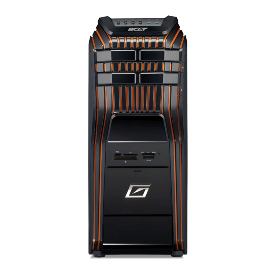
System Components This section is a virtual tour of the system’s interior and exterior components. Front Panel Component Power button USB 2.0 ports Master optical drive crab Slave optical drive crab XD(XD-Picture) slot Micro SD slot CF I/II (CompactFlash Type I/II) slot Chapter 1 Component Removable HDD bay door... -
Page 14: Rear Panel
Rear Panel Component Power connector PS2 keyboard port USB 2.0 ports Line-out jack Microphone/speaker-out/line-in jack Expansion slot(graphics card and Mode card etc.) Line-in jack RJ45 LAN connector System Fan PS2 mouse port Line-out jack USB 2.0 ports Power switch Chapter 1... -
Page 15: Hardware Specifications And Configurations
Intel H57 USB controller Intel H57 SATA controller Intel H57 Super I/O controller ITE 8721F-BX Chapter 1 Specification AMI Kernel with Acer skin P01-A0 SPI ROM SMBIOS 2.6/PCI2.3/PCIE1.1/PCIE2.0/USB2.0 Support BBS spec 1st priority:HDD 2nd priority:CD&DVD 3th priority:Removable device 4th priority:LAN Description Press while the system is booting to enter BIOS Setup Utility. -
Page 16: Memory Combinations
Memory Combinations Slot Memory Slot 1 1MB,2GB,4GB Slot 2 1MB,2GB,4GB Slot 3 1MB,2GB,4GB Slot 4 1MB,2GB,4GB Maximum System Memory Supported System Memory Item Memory slot number Support Memory size per socket Support memory type Support memory interface Support memory voltage Support memory module package Support to parity check feature Support to error correction code (ECC) feature No... -
Page 17: Sata Interface
SATA Interface Item SATA controller Number of SATA channel Support mode USB Port Item Universal HCI USB Class USB Connectors Quantity Environmental Requirements Item Specification Temperature Operating +5°C ~ +35°C Non-operating -20 ~ +60°C (Storage package) Humidity Operating 15% to 80% RH Non-operating 10% to 90% RH Vibration... -
Page 18: Power Management Function(Acpi Support Function)
Power Management Function(ACPI support function) Device Standby Mode Independent power management timer for hard disk drive devices(0-15 minutes,time step=1minute). • Hard Disk drive goes into Standby mode(for ATA standard interface). • Disable V-sync to control the VESA DPMS monitor. • Resume method:device activated (keyboard for DOS, keyboard &mouse for Windows. -
Page 19: System Utilities
System Utilities CMOS Setup Utility CMOS setup is a hardware configuration program built into the system ROM, called the complementary metal- oxide semiconductor (CMOS) Setup Utility. Since most systems are already properly configured and optimized, there is no need to run this utility. You will need to run this utility under the following conditions. When changing the system configuration settings •... -
Page 20: Entering Cmos Setup
Entering CMOS setup Turn on the server and the monitor. If the server is already turned on, close all open applications, then restart the server. During POST, press Delete. If you fail to press Delete before POST is completed, you will need to restart the server. The Setup Main menu will be displayed showing the Setup’s menu bar. -
Page 21: Setup Utility Menus
Setup Utility Menus The Setup Main menu includes the following main setup categories. Parameter Description Product Information This page shows the relevant information of the main board Standard CMOS Features This setup page includes all the items in standard compatible BIOS Advanced Chipset Features This setup page includes all the items of Award special enhanced features Advanced Chipset Features... -
Page 22: Product Information
Product Information The Product Information menu displays basic information about the system. These entries are for your reference only and are not user-configurable. Parameter Description Processor Type Type of CPU installed on the system. Processor Speed Speed of the CPU installed on the system. System Memory Total size of system memory installed on the system. -
Page 23: Standard Cmos Features
Standard CMOS Features Parameter Description System Date Set the date following the weekday-month-day-year format. System Time Set the system time following the hour-minute-second format. AHCI Port 1~6 This motherboard supports six SATA channels, each channel allows one SATA device to be installed. Use these items to configure each device on the SATA channel. -
Page 24: Advanced Bios Feature
Advanced BIOS Feature Quick Boot Allows you to decrease the time it takes to boot the computer by shortening or skipping certain standard booting process. Quiet Boot When enabled, the BIOS splash screen displays during startup. When disabled, the diagnostic screen displays during startup. 1st/2nd/3rd/4th Boot Device Specifies the boot order from the available devices. -
Page 25: Advanced Chipset Features
Advanced Chipset Features Intel EIST This item allows users to enable or disable the EIST (Enhanced Intel SpeedStep technology). Intel Turbo Boost This item allows users to enable or disable the Intel Turbo Boost. Intel XD Bit This item allows users to enable or disable the Intel XD Bit. Intel VT Hardware Virtualization Technology enables processor feature for running multiplesimultaneous Virtual Machines allowing specialized software... -
Page 26: Integrated Peripherals
Integrated Peripherals Parameter Description Onboard SATA Controller Enables or disables the onboard SATA controller. Onboard SATA Mode Select an operating mode for the onboard SATA. Onboard USB Controller Enables or disables the onboard USB controller. Legacy USB Support Enables or disables support for legacy USB devices. USB Storage Emulation If Auto, USB device equal or less than 2GB will be emulated as Floppy and remaining as harddrive. -
Page 27: Power Management Setup
Power Management Setup Parameter Description ACPI Suspend Mode Select an ACPI state. Deep Power Off Mode Select the Deep power off Mode Power On by RTC Alarm Enables or Disables to wake up the system by RTC Alarm Function Power On by PCIE Devices Enables or disables to wake up the system from a power saving mode through an event on PCI Express device. -
Page 28: Pc Health Status
PC Health Status Parameter Description Smart Fan Enables or disables the smart system fan control function. Option Enabled Disabled Chapter 2... - Page 29 Frequency/Voltage Control Press Enter: Parameter Description Clock to All DIMM/PCI/PCIE When this item is disabled, BIOS will enable the clock signal of free DIMM/PCI slots. Spread Spectrum Enables or disables the reduction of the mainboard’s EMI. Note: Remember to disable the Spread Spectrum feature if you are overclocking.
-
Page 30: Bios Security Features
BIOS Security Features Parameter Description Supervisor Password Indicates the status of the supervisor password. User Password Indicates the status of the user password. Change Supervisor Supervisor password prevents unauthorized access to the BIOS Setup Utility. Password Press Enter to change the Supervisor password. Setting a supervisor password Use the up/down arrow keys to select Change Supervisor Password menu then press Enter. -
Page 31: Load Default Settings
Load Default Settings The Load Default Settings menu allows you to load the default settings for all BIOS setup parameters. Setup defaults are quite demanding in terms of resources consumption. If you are using low-speed memory chips or other kinds of low-performance components and you choose to load these settings, the system might not function properly. - Page 32 Save & Exit Setup The Save & Exit Setup menu allows you to save changes made and close the Setup Utility. Chapter 2...
-
Page 33: Exit Without Saving
Exit Without Saving The Exit Without Saving menu allows you to discard changes made and close the Setup Utility. Chapter 2... -
Page 34: System Disassembly
System Disassembly This chapter contains step-by-step procedures on how to disassemble the desktop computer for maintenance and troubleshooting. Disassembly Requirements To disassemble the computer, you need the following tools: Wrist grounding strap and conductive mat for preventing electrostatic discharge • Flat-blade screwdriver •... -
Page 35: Pre-Disassembly Procedure
Pre-disassembly Procedure Before proceeding with the disassembly procedure, perform the steps listed below: Turn off the system and all the peripherals connected to it. Unplug the power cord from the power outlets. Unplug the power cord from the system. Unplug all peripheral cables from the system. Place the system unit on a flat, stable surface. -
Page 36: Removing The Side Panel
Removing the Side Panel Remove the two screws located on the rear edge of the side panel. Slide the side panel toward the back of the chassis until the tabs on the cover disengage with the slots on the chassis. Lift the side panel away from the server and put it aside for reinstallation later. -
Page 37: Removing The Front Bezel
Removing the Front Bezel Release the front bezel retention tabs from the chassis interior. Pull the bezel away from the chassis. Chapter 3... -
Page 38: Removing The Heat Sink Fan Assembly
Removing the Heat Sink Fan Assembly WARNING:The heat sink becomes very hot when the system is on. NEVER touch the heat sink with any metal or with your hands. Disconnect the fan cable from the mainboard. Use a long-nosed screwdriver to loosen the four screws on the heat sink, in the order as shown below. Chapter 3... - Page 39 Lift the heat sink fan assembly away from the mainboard. Chapter 3...
-
Page 40: Removing The Processor
Removing the Processor IMPORTANT:Before removing a processor from the mainboard, make sure to create a backup file of all important data. WARNING:The processor becomes very hot when the system is on. Allow it to cool off first before handling. Release the load lever. Lift the load lever and load plate to the fully open, upright position (1) and (2). -
Page 41: Removing The Vga Card
Removing the VGA Card Remove the screw from the chassis. Open the PCI-Door as below. Remove the two screws that secures the card to the chassis. Chapter 3... - Page 42 Gently pull the card to remove it from the mainboard. Chapter 3...
-
Page 43: Removing The Wireless Lan Card
Removing the Wireless LAN Card Remove the screw that secures the card to the chassis. Gently pull the card to remove it from the mainboard. Chapter 3... -
Page 44: Removing The Memory Modules
Removing the Memory Modules IMPORTANT:Before removing any DIMM from the memory board, make sure to create a backup file of all important data. Press the holding clips on both sides of the DIMM slot outward to release the DIMM (1). Gently pull the DIMM upward to pull it away from the chassis (2). -
Page 45: Removing The System Fan
Removing the System Fan Disconnector the power cable from the motherboard. Release the four screws fastening the system fan. Remove the system Fan from the chassis. Chapter 3... -
Page 46: Removing The Daughter Board
Removing the Daughter Board Disconnect the daughter board cable from the motherboard, and then take out the cable from the cable retention clip. Remove the screw that secures the chassis to the daughter board. Take out the daughter board. Chapter 3... - Page 47 Remove the two screws that secure the USB board to the bracket. Pull the USB board out of the bracket. Chapter 3...
-
Page 48: Removing Other Side Panel
Removing Other Side Panel Remove the two screws located on the rear edge of the side panel. Slide the side panel toward the back of the chassis until the tabs on the cover disengage with the slots on the chassis. Lift the side panel away from the server and put it aside for reinstallation later. -
Page 49: Removing The Hard Disk Drive
Removing the Hard Disk Drive Disconnect the data and power cables from the rear of the optical drive and the mainboard. Disconnect the other end of the data cable from the mainboard. Remove the HDD bracket Remove the screw that secures the HDD bracket to the ODD bracket. Chapter 3... - Page 50 Lift the bracket up and turn it over. Place the bracket on a clean, static-free work surface. Remove the HDD module Remove the four screws secure the HDD module to the HDD bracket. Slide the HDD out of the bracket. Chapter 3...
-
Page 51: Removing The Removable Hard Disk Drive
Removing the Removable Hard Disk Drive Disconnect the removable HDD cable. Disconnect the removable HDD date cable from the motherboard. Use a knife to cut off the PE belt then disconnector the cable. Disconnector the power cable of the removable HDD. Chapter 3... - Page 52 Remove the four screws. Pull the two removable HDD cables. Remove the removable HDD module. Gently push the drive block key rightward,then open the door. Chapter 3...
- Page 53 Slide the removable HDD tray out of the removable HDD bracket. Use a hand to open out the removable HDD tray until the hook of HDD bracket away from the HDD screw bore. then use other hand to take out the HDD module. Chapter 3...
-
Page 54: Removing The Optical Drive
Removing the Optical Drive Disconnect the data and power cable from the rear of the optical drive. Disconnect the other end of the data cable from the mainboard. Remove the four screws from the optical drive. Chapter 3... - Page 55 Remove the four screws from the optical drive on the other side. Pull the drive out of the drive. Remove the slave optical drive with the same way. Chapter 3...
-
Page 56: Removing The Power Supply
Removing the Power Supply Disconnect the 4-pin and 24-pin power supply cables from the mainboard. Remove the four screws that secures the power supply to the rear panel. Lift the power supply module out of the chassis. Chapter 3... -
Page 57: Removing The Motherboard
Removing the Motherboard Disconnect the front audio,card reader,front USB,front panel cable from the motherboard. Take out the front audio cable from the cable clip and disassemble the cable clip. Open cable clip then take out these cables. at the same time disassemble the cable clip. Chapter 3... - Page 58 Remove the eight screws that secure the mainboard to the chassis. Note: Circuit boards >10 cm² has been highlighted with the yellow rectangle as above image shows. Please detach the Circuit boards and follow local regulations for disposal. Lift the board from the chassis. Chapter 3...
- Page 59 Remove the RTC battery. Note :RTC battery has been highlighted with the yellow circle as above image shows.Please detach the RTC battery and follow local regulations for disposal. Punching in IO Shield then you can remove it. Chapter 3...
-
Page 60: Removing The Card Reader
Removing the Card Reader Remove the three screws that secure the bracket to the chassis. Pull the card reader bracket out of the chassis. Use a long-nosed screwdriver to remove the two screws. Chapter 3... - Page 61 Pull the card reader board out of the bracket. Chapter 3...
-
Page 62: Removing The Top Cover
Removing the Top Cover Open the cable clip,then take out the Power switch/Front I/O /Audio cable. Gently release the top bezel retention tabs from the chassis interior. Pull the top cover away from the chassis. Chapter 3... -
Page 63: Removing The Power Switch And Led Cable Assembly
Removing the Power Switch and LED Cable Assembly Release the two locking tabs and take out the front panel cable. Release the two locking tabs (1) and gently take out the power switch and LED cable assemble(2). Release the HDD and LAN LED. Release the locking tabs (1) and gently pull the HDD LED cable out (2). - Page 64 Separate the power switch and LED cable assemble from the top cover. Release the locking tabs (1) and gently pull out the power LED cable (2). Gently pull out the other power LED cable with the same way. Grasp the power switch and LED cable bracket,and Release the two locking tabs (1), pull power switch cable out of the bracket (2).
-
Page 65: Removing The Front I/O And Usb Board
Removing the Front I/O and USB Board Remove the two screws that secure the bracket to the chassis. Lift the bracket out of the chassis. Chapter 3... - Page 66 Use a long-nosed screwdriver to remove the two screws. Grasp the bracket then gently Pull the USB board out of the bracket.
-
Page 67: System Troubleshooting
This chapter provides instructions on how to troubleshoot system hardware problems. Hardware Diagnostic Procedure IMPORTANT:The diagnostic tests described in this chapter are only intended to test Acer products. Non-Acer products, prototype cards, or modified options can give false errors and invalid system responses. -
Page 68: System Check Procedures
Verify that components are properly seated. Verify that all cable connectors inside the system are firmly and correctly attached to their appropriate connectors. Verify that all components are Acer-qualified and supported. 10. Replace the system covers. 11. Power on the system. -
Page 69: Beep Codes
Beep Codes Beep codes are used by the BIOS to indicate a serious or fatal error to the end user. Beep codes are used when an error occurs before the system video has been initialized. Beep codes will be generated by the system board speaker, commonly referred to as the PC speaker. -
Page 70: Checkpoints
Checkpoints A checkpoint is either a byte or word value output to I/O port 80h.The BIOS outputs checkpoints throughout bootblock and Power-On Self Test (POST) to indicate the task the system is currently executing. Checkpoint sare very useful in aiding software developers or technicians in debugging problems that occur during the pre- boot process. - Page 71 Checkpoint Restore CPUID value back into register. Give control to BIOS POST (ExecutePOSTKernel). See POST Code Checkpoints section of document for more information. System is waking from ACPI S3 state. E1-E8 EC- OEM memory detection/configuration error. This range is reserved for chipset vendors & system manufacturers.
-
Page 72: Bootblock Recovery Code Checkpoints
Bootblock Recovery Code Checkpoints The Bootblock recovery code gets control when the BIOS determines that a BIOS recovery needs to occur because the user has forced the update or the BIOS checksum is corrupt. The following table describes the type of checkpoints that may occur during the Bootblock recovery portion of the BIOS. NOTE: Checkpoints may differ between different platforms based on system configuration. -
Page 73: Bios Recovery
BIOS Recovery This function only effects when the BIOS BootBlock section is healthy. Allow to execute recovery function media: FDD / USB storage / ODD. The recovery media to support Boot function is unnecessary. Recovery step as follow: 4-1. Copy the latest BIOS ROM file to the root directory of recovery media. 4-2. -
Page 74: Jumper And Connector Information
Chapter 5 Jumper and Connector Information M/B Placement Chapter 5... - Page 75 Label CPU Socket LGA1156 socket for Intel® Lynnfield/Havendale/ Clarkdale processors CPU_FAN CPU cooling fan connector DIMM1~4 240-pin DDR3 SDRAM slots ATX1 Standard 24-pin ATX power connector SPI_DEBUG SPI debug header SATA1~6 Serial ATA connectors F_PANEL Front panel switch/LED header F_USB3~4 Front panel USB headers CLR_CMOS Clear CMOS jumper...
-
Page 76: Jumper Setting
Jumper Setting The section explains how to set jumper for correct configuration of the mainboard. Setting Jumper Use the motherboard jumpers to set system configuration options. Jumpers with more Than one pin are numbered. When setting the jumpers, ensure that the jumper caps are Placed on the correct pins. The illustrations show a 2-pin jumper.When the jumper cap is placed on bothpins, the jumper is SHORT. - Page 77 Jumper Settings Jumper Type Descriptio CLR_CMOS 3-pin CLEAR CMOS ME_DISABLE 3-pin ME_DISABLE Setting (default) 1-2: NORMAL 2-3: CLEAR Before clearing theCMOS, make sure toturn the system off. 1-2: NORMAL 2-3: ME_DISABLE Chapter 5...
-
Page 78: Connecting Optional Devices
Connecting Optional Devices Refer to the following for information on connecting the motherboard’s optionaldevices: SATA1~6: Serial ATA connectors These connectors are used to support the new Serial ATA devices for the highest datatransfer rates (3.0 Gb/s), simpler disk drive cabling and easier PC assembly. It elimi-nates limitations of the current Parallel ATA interface. - Page 79 F_USB1~4: Front Panel USB headers The motherboard has four USB ports installed on the rear edge I/O port array.Additionally, some computer cases have USB ports at the front of the case. If youhave this kind of case, use auxiliary USB connector to connect the front-mountedports to the motherboard.
-
Page 80: Connecting Case Components
Connecting Case Components After you have installed the motherboard into a case, you can begin connecting themotherboard components. Refer to the following: Connect the CPU cooling fan cable to CPU_FAN. Connect the standard power supply connector to ATX1. Connect the case switches and indicator LEDs to the F_PANEL. Connect the system cooling fan connector to SYS_FAN. -
Page 81: Front Panel Header
Signal Name Ground Ground PWRGD +5VSB +12V +12V +3.3V SYS_FAN1: System Cooling FAN Power Connector Signal Name +12V Sense ATX12V1: ATX 12V Power Connector Front Panel Header The front panel header (F_PANEL) provides a standard set of switch and LEDheaders commonly found on ATX or micro-ATX cases. -
Page 82: Fru (Field Replaceable Unit) List
To scrap or to return the defective parts, follow the local government ordinance or regulations on • how to dispose it properly, or follow the rules set by your regional Acer office on how to return it. This document will be updated as more information about the FRU list becomes available. -
Page 83: Predator G5900 Exploded Diagram
Predator G5900 Exploded Diagram NOTE: This section will be updated when more information becomes available. Chapter 6... - Page 84 ITEM NAME 1-RIGHT-SIDE-X1 2-TOP-COVER CHASSIS-HANDLE 2-TOP-COVER07 1-TOP-PLATE SCREW_M632-6 G5-ASSY-FRONT-IO-BD- NEW1_ASM(TOP IO) 1-ODD-BKT-X4 1-FBB-PLATE-0611 16IN5-WITH-1394-X1_ASM(MCR) HT-361-HDD-CARRIER 2-FRONT-COVER GJ-HDD-BKT-NEW Chapter 6 Q’TY ITEM 1-HDD-BKT-X2 THUMB-SCREW-2 HDD-RUBBER CUS-LV2122K 1-LETF-SIDE-X1 35FNF_AOO 2-PCI-SHIELD CABLE-CLIP PCI-DOOR-01 ACER_JOPLIN_RUBBER-BACK-FOOT 1-MB-BKT-X4 ATX-POWER-AA 1-BACK-X4 NAME Q’TY...
-
Page 85: Predator G5900 Fru List
Predator G5900 FRU List Category Main board MB Kit aSampras_G EIH57MK for G5 Intel H57 Realtek RTL8111E Giga LAN ATX W/O 1394 V1.0 LF w/o onboard VGA Mainboard aSampras_G EIH57M for G5 Intel H57 Realtek RTL8111E Giga LAN ATX W/O 1394 V1.0... - Page 86 Category CPU Intel Core i7 875K LGA 2.93G 8M 1333 1156 95W B-1 Quad Core CPU Intel Core i7 870 LGA 2.93G 8M 1333 1156 95W B-1 Quad Core CPU Intel Core i7 860 LGA 2.8G 8M 1333 1156 95W B-1 Quad Core CPU Intel Core i5 750 LGA 2.66G 8M 1333 1156 95W B-1 CPU Intel Core i5 680 LGA 3.6G 4M 1333 1156...
- Page 87 Category "HDD HGST 3.5"" 7200rpm 640GB HDS721064CLA332 (Jupiter) SATA II 32MB LF F/ W:3EA" "HDD HGST 3.5"" 7200rpm 1000GB HDS721010CLA332 (Jupiter) SATA II 32MB LF F/ W:3EA" "HDD HGST 3.5"" 5700rpm 1000GB HCS5C1010CLA382 ( Cool Spin Jupiter) SATA II 8MB LF F/W:3EA" "HDD SEAGATE 3.5""...
- Page 88 Category ODD TOSHIBA DVD-ROM HH DL 16X TS-H353C LF Black Bezel SATA (HF+Win7) ODD HLDS Super-Multi DRIVE HH DL 16X GH60N LF+HF Black Bezel SATA HF+Win7 ODD PLDS Super-Multi DRIVE HH DL 16X DH- 16ABSH LF Black Bezel (HF+Win7) SATA ODD TOSHIBA Super-Multi DRIVE HH DL 16X TS-H653G LF Black Bezel SATA (HF+Win7) ODD PLDS BD ROM HH DL 4X DH-4O3S LF...
- Page 89 Category LITE-ON PS-6451-5AE 500W Active PFC 100- 127/220-240V FSP750-80APG 750W Active PFC (A01004) 100- 127V/220-240V PSU FSP FSP750-80APG 750W Active PFC (A01002) 100-240V Wireless LAN WN7600R, WLAN PCI-Ex1 card 802.11 b/g/n 1T x 2R, Ralink 1T x 2R, RT2790+RT2720 WN7601R, Ralink RT3090, 802.11b/g/n 1x1 WLAN PCI-E x1 card Mouse Lite-on USB SM-9020B with black color...
-
Page 90: Intel Raid Sop
Intel RAID SOP 1.INTEL® MATRIX STORAGE TECHNOLOGY CHECK(DOS) 1-1: Create SATA RAID 0 Step 1:Shut down the EUT, unplug the power cable,connect two SATA HDDS to EUT , check the EUT all devices are connect/plug ok. Step 2:Press "PWR-BTTN" to power on the EUT,Load BIOS default setting . Step 3:At "Integrated_Peripherals"... - Page 91 Step 7:Select "RAID0(Stripe)" at "RAID Level". Picture3 Step 8:You can select the "Strip Size" and define RAID capacity in "Capactity". Picture4 Chapter 7...
- Page 92 Step 9:Press "Create Volume" to create RAID0,it will pop the warning message that all data will be lost,"press "Y" to confirm it. Step 10:It will back to create RAID interface,then press "ESC" or select 4 to exit and install OS. 1-2: Create SATA RAID 1 Step 1:Shut down the EUT, unplug the power cable,connect two SATA HDDS to EUT , check the EUT all devices are connect/plug ok.
- Page 93 Step 8:You can select the "Strip Size" and define RAID capacity in "Capactity". Step 9:Press "Create Volume" to create RAID1,it will pop the warning message that all data will be lost,"press "Y" to confirm it. Step 10:It will back to create RAID interface,then press "ESC" or select 4 to exit and install OS. 1-3: Create SATA RAID 5 Step 1:Shut down the EUT, unplug the power cable,connect three SATA HDDS to EUT , check the EUT all devices are connect/plug ok.
- Page 94 Step 7:Select "RAID0(Stripe)" at "RAID Level". Step 8:Select two HDDs in "Disk" by space key. Picture8 Step 9:Press "Enter" to finish HDD selection and it will back to RAID creation interface. Step 10:Repeat RAID1 creation step and exit,then install OS. Chapter 7...
- Page 95 Intel RAID SOP (Windows for WIN7) 2.Intel(R) Matrix Storage Console 2-1:Create a“RAID Ready” System into" RAID 0" with two Hard Drives by‘Create RAID Volume from Existing HDD Drive ’. Step 1:Install Win7 OS with one SATA HDD. Step 2:Shut down the system,then add one Serial ATA hard drive in the system. Step 3:Boot to OS desktop, open the Intel®...
- Page 96 Step 5:Click "Next" at create a RAID volume window. Picture3 Step 6:Key the name in "Volume Name" and select "RAID 0" in RAID Level. Picture4 Step 7:Select minimum HDD as "Source Hard Drive". Picture5 Chapter 7...
- Page 97 Picture6 Step 8:Select Menber Hard Drive(s). Picture7 Chapter 7...
- Page 98 Step 9:Specify Volume Size then press "next". Step 10:Press "next" to finish setup and start create RAID0. Step 11:It may takes half and hours to create RAID0.After create completely,it will ask to reboot to finish create RAID0. 2-2:Create a“RAID Ready” System into" RAID 1" with two Hard Drives by‘Create RAID Volume from Existing HDD Drive ’.
- Page 99 Step 6:Key the name in "Volume Name" and select "RAID 1" in RAID Level. Step 7:Select minimum HDD as "Source Hard Drive". Step 8:Select Menber Hard Drive(s). Step 9:Specify Volume Size then press "next". Step 10:Press "next" to finish setup and start create RAID1. Step 11:It may takes half and hours to create RAID1.After create completely,it will ask to reboot to finish create RAID1.
- Page 100 Step 6:Key the name in "Volume Name" and select "RAID 5" in RAID Level. Picture11 Step 7:Select minimum HDD as "Source Hard Drive". Picture12 Chapter 7...
- Page 101 Step 8:At least select two HDD as Menber Hard Drive(s). Step 9:Specify Volume Size then press "next". Step 10:Press "next" to finish setup and start create RAID5. Step 11:It may takes half and hours to create RAID5.After create completely,it will ask to reboot to finish create RAID5.
- Page 102 Step 7:Select two HDDs as "Source Hard Drive". Step 8:At least select two HDD as Menber Hard Drive(s). Step 9:Specify Volume Size then press "next". Step 10:Press "next" to finish setup and start create RAID 10. Step 11:It may takes half and hours to create RAID 10.After create completely,it will ask to reboot to finish create RAID10.
- Page 103 Step 5:Click "Next" at create a RAID volume window. Step 6:Key the name in "Volume Name" and select "RAID 0" in RAID Level. Step 7:At least select two HDDs as "Volume Location". Picture17 Step 8:Specify Volume Size then press "next". Picture18 Step 9:Press "next"...
- Page 104 2-6:Create a“RAID Ready” System into" RAID 1" with two Hard Drives by ‘Create RAID Volume ’. Step 1:Install WIN7 OS with one SATA HDD. Step 2:Shut down the system,then add another two serial ATA hard drives in the system. Step 3:Boot to OS desktop, open the Intel® Matrix Storage Console. Step 4:Click on the by‘Create RAID Volume’...