Table of Contents
Advertisement
Quick Links
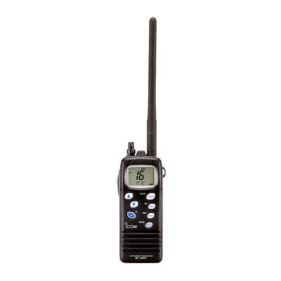
INSTRUCTION MANUAL
VHF MARINE TRANSCEIVER
iM1V
This device complies with Part 15 of the FCC rules. Operation is sub-
ject to the following two conditions: (1) This device may not cause
harmful interference, and (2) this device must accept any interference
received, including interference that may cause undesired operation.
Advertisement
Table of Contents

Related Manuals for Icom IC-M1V


Summary of Contents for Icom IC-M1V
-
Page 1: Instruction Manual
INSTRUCTION MANUAL VHF MARINE TRANSCEIVER iM1V This device complies with Part 15 of the FCC rules. Operation is sub- ject to the following two conditions: (1) This device may not cause harmful interference, and (2) this device must accept any interference received, including interference that may cause undesired operation. -
Page 2: Foreword
FOREWORD CAUTIONS Thank you for purchasing this Icom product. The IC-M1V R WARNING! NEVER connect the transceiver to an AC is designed and built with Icom’s superi- MARINE TRANSCEIVER outlet. This may pose a fire hazard or result in an electric or technology and craftsmanship. -
Page 3: In Case Of Emergency
For U.S.A. only tance required. CAUTION: Changes or modifications to this device, not ex- pressly approved by Icom Inc., could void your authority to 6. Any other information which might facil- operate this device under FCC regulations. itate the rescue. -
Page 4: Table Of Contents
TABLE OF CONTENTS Scan types ..............11 FOREWORD ............... i IMPORTANT ................ i Setting tag channels ..........12 EXPLICIT DEFINITIONS ............. i Starting a scan ............12 CAUTIONS ..............i, ii 6 SET MODE .............. 13–14 IN CASE OF EMERGENCY ..........ii SET mode programming ........... -
Page 5: Operating Rules
OPERATING RULES × PRIORITIES (2) OPERATOR’S LICENSE A Restricted Radiotelephone Operator Permit is the license q Read all rules and regulations pertaining to priorities an most often held by small vessel radio operators when a radio keep an up-to-date copy handy. Safety and distress calls is not required for safety purposes. -
Page 6: Panel Description
PANEL DESCRIPTION q ANTENNA CONNECTOR Panel description Connects the supplied antenna. (p. 00) w PTT SWITCH [PTT] Transmits during push and hold; receives during release. (p. 00) e MONITOR SWITCH [MONI] Opens the squelch and monitors the operating channel while being pushed. While turning power ON, enters the SET mode and pro- ceeds the SET mode contents when pushed. -
Page 7: Panel Description
PANEL DESCRIPTION t CHANNEL UP/DOWN SWITCHES [Y Y ]/[Z Z ] !0 DUALWATCH/TRI-WATCH SWITCH [DW•TRI] (p. 00) Push either switch to change the operating channel. (p. Starts dualwatch when pushed momentarily. Starts tri-watch when pushed for 2 sec. Push either switch to change the setting during set Stops dualwatch/tri-watch when either is activated. -
Page 8: Function Display
PANEL DESCRIPTION Function display q BUSY INDICATOR (p. 00) Appears while receiving a signal or while the squelch opens. w TRANSMIT INDICATOR (p. 00) Appears while transmitting. e CHANNEL GROUP INDICATORS (p. 00) Appears “USA” when U.S.A.; “INT” when international; CALL LOW “CAN”... - Page 9 PANEL DESCRIPTION u BATTERY INDICATOR !3 WEATHER CHANNEL/WEATHER ALERT INDICATOR Indicates remaining battery power. • “WX” appears when weather channel group is selected. • “ALT” appears while the weather alert function is acti- Indication vated; blinks when alert tone is received. Charging Exhausts !4 LOW POWER INDICATOR (p.
- Page 10 SUPPLIED ACCESSORY AND ATTACHMENT × Supplied accessories × Flexible antenna attachment The following accessories are supplied: Qty. Insert the supplied antenna into the antenna connector and screw q Flexible antenna (FA-S57V) .........1 down the antenna as shown in w Battery pack (BP-215) ..........1 the diagram at right.
-
Page 11: Basic Operation
BASIC OPERATION Channel selection × Channel 16 × Channel 9 (Call channels) Channel 16 is the distress channel. It is used for establishing Channel 9 is the pleasure call channel. Each regular channel initial contact with another station and for emergency com- group has separate call channels. -
Page 12: Basic Operation
Administration) broadcasts. q Push [CH/WX] to select a regular channel. The IC-M1V can detect a weather alert tone on the selected • If a weather channel appears, push [CH/WX] again. weather channel while receiving the channel, during standby w Push [Y]/[Z] to select a channel. -
Page 13: Receiving And Transmitting
BASIC OPERATION Receiving and transmitting IMPORTANT: To maximize the readability of your trans- mitted signal (voice), pause a few sec. after pushing [PTT], CAUTION: hold the microphone 10 to 15 cm (4 to 6 inches) from your Transmitting without an antenna may dam- mouth and speak at a normal voice level. -
Page 14: Optional Voice Scrambler Operation
BASIC OPERATION Lock function Optional voice scrambler operation This function electronically locks all keys and switches to pre- vent accidental frequency changes and function access. × Activating the scrambler Push [H/L•LOCK] for 2 sec. to turn the lock function ON The optional voice scrambler provides private communica- and OFF. - Page 15 BASIC OPERATION Call channel programming r Push [Y]/[Z] to select the desired The call channel key is used to select channel 9, however, TAG CALL you can program your most often-used channels in each channel. channel group for quick recall. q Push [CH/WX•U/I/C] for 2 sec.
-
Page 16: Scan Operation
SCAN OPERATIONS Scan types Scanning is an efficient way to locate signals quickly over a Set the tag channels (scanned channel) before scanning. wide frequency range. The transceiver has priority scan and Clear the tag channels which inconveniently stop scanning, normal scan. -
Page 17: Scan Operation
SCAN OPERATION Setting tag channels Starting a scan For more efficient scanning, add desired channels as tag Set scan type, weather alert function, scan resume timer and channels or clear tag channels for unwanted channels. auto scan function in advance using SET mode. (p. 14) Channels set as non-tag channels will be skipped during q Select the desired channel group (USA, CAN, INT) by scanning. - Page 18 DUAL WATCH/TRI-WATCH Description Operation q Select the desired operating channel. Dualwatch monitors channel 16 while you are receiving an- w Push [DW•TRI] momentarily to start dualwatch; push other channel; tri-watch monitors channel 16 and the call channel while receiving another channel. [DW•TRI] for 2 sec.
- Page 19 About the channel comment Channel comment programming q Push [Y]/[Z] to select a channel to The IC-M1V has a capability to assign up to 10-characters channel comment for each operating channel, includes program. • Push [CH/WX•U/I/C] for 2 sec. to select weather channel.
-
Page 20: Set Mode
SET MODE SET mode programming SET mode items q Turn power OFF. SET mode is used to change the condi- × Beep tone “BEEP” w While pushing [MONI], turn power tions of 10 transceiver functions: beep You can select silent operation by turn- tone function, weather alert function, ON and continue pushing [MONI] ing beep tones OFF or you can have... - Page 21 SET MODE × Weather alert function × Scan type selection × Scan resume timer “WX ALERT” “SCAN TYPE” “SCAN TIMER” An NOAA broadcast station transmits The transceiver has 2 scan types: nor- The scan resume timer can be selected an weather alert tone before an impor- mal scan and priority scan.
- Page 22 SET MODE × Auto scan function × Automatic backlighting × Power save function “AUTO SCAN” “BACKLIGHT” “POWER SAVE” While in standby, this function automat- This function is convenient for nighttime The power saver function reduces cur- ically starts the desired scan (normal or operation.
- Page 23 SET MODE × Self check function × Scrambler unit selection × Scrambler code “SELF CHECK” “SCRAM UNIT” “SCRAM CODE” The self check function checks trans- There are 128 codes (00 to 127) avail- This item appears only when voice ceiver conditions by itself and informs able with UT-98 or 32 codes (00 to 31) scrambler unit is installed.
-
Page 24: Battery Charging
BATTERY CHARGING Battery cautions Battery charging NEVER incinerate used battery packs. Internal battery gas Prior to using the transceiver for the first time, the battery may cause an explosion. pack must be fully charged for optimum life and operation. NEVER immerse the battery pack in water. If the battery pack CAUTION: To avoid damage to the transceiver, turn it OFF becomes wet, be sure to wipe it dry BEFORE attaching it to while charging. - Page 25 BATTERY CHARGER × Attaching the AD-95 to a desktop × Charging q Connect the AC adapter (BC-122) or optional cable (CP- as shown below. 17L or OPC-515L) w Insert the battery pack only or with the transceiver into the charger. Eyelet: •...
- Page 26 SPEAKER-MICROPHONE Speaker-microphone Attachment descriptions Insert the connector of the speaker-microphone into the [SP MIC] connector on the transceiver and rotates (screws) IMPORTANT: KEEP the [SP MIC] jack cover attached the connector cover as shown in the diagram below. (transceiver) when speaker-microphone is not in use. Water will not coming into the transceiver even the cover is not attached, however, the terminals (pins) become rusty when the connector has wet.
-
Page 27: Troubleshooting
TROUBLESHOOTING PROBLEM POSSIBLE CAUSE SOLUTION REF. No power comes ON. • The battery is exhausted. • Recharge the battery pack. p. 15 • Bad connection to the battery pack. • Check the connection to the transceiver. p. 2 No sound comes from •... -
Page 28: Channel List
CHANNEL LIST Channel Number Frequency (MHz) Channel comment Channel Number Frequency (MHz) Channel comment USA INT CAN Transmit Receive USA INT CAN Transmit Receive 156.050 160.650 TELEPHONE 19A 156.950 156.950 COMMERCIAL 156.050 156.050 VTS 157.000 161.600 PORT OPR 156.100 160.700 TELEPHONE 157.000 157.000 PORT OPR 156.100 156.100 157.050 161.650 INTL... - Page 29 CHANNEL LIST CHANNEL NAME KEY 64A 156.225 156.225 COMMERCIAL Channel Number Frequency (MHz) Channel comment TELEPHONE Channel Number Frequency (MHz) Channel comment USA INT CAN Transmit Receive public correspondence USA INT CAN Transmit Receive 157.175 161.775 CCG PLEASURE 156.275 160.875 INTL 83A 157.175 157.175 CCG pleasure boat use 65A 65A 65A 156.275 156.275 PORT OPR...
-
Page 30: Specifications And Options
200 mA max. *Tx:Rx:Stand-by=5:5:90 Power saved ?? mA typ. • CP-17L CIGARETTE LIGHTER CABLE • Power supply requirement : Icom battery pack, BP-215 Connects to a ship’s or vehicle’s cigarette lighter socket for use (12 V) • Frequency stability : ±10 ppm (–20°C to +60°C;... - Page 31 INDEX...
- Page 32 Count on us! A-5373H-1US Printed in Japan 6-9-16 Kamihigashi, Hirano-ku, Osaka 547-0002 Japan © 1999 Icom Inc.