Table of Contents
Advertisement
Quick Links
Advertisement
Chapters
Table of Contents

Related Manuals for Dürkopp Adler 667


Summary of Contents for Dürkopp Adler 667
- Page 1 Operating Instructions...
- Page 2 All Rights Reserved. Property of Dürkopp Adler and copyright protected. Any use of this content, or part thereof, is subject to prior writ- ten approval by Dürkopp Adler. Copyright © Dürkopp Adler - 2011...
-
Page 3: Table Of Contents
3.2.2 Function of supplementary thread tension in relation to the sewing foot lift and the Speedomat for subclass 667-180312 and 667-180332......................10 Opening the thread tension ......................... 11 Turning the supplementary thread tension on and off for subclasses 667-180312 and 667-180332 ..11 Adjusting the thread regulator ........................12 Winding on the hook thread ........................13 Changing the hook-thread bobbin ...................... -
Page 5: General Safety
General safety This instruction manual is intended to help familiarize the user with the machine and to enable correct utilisation. The instruction manual contains important information on how to operate the machine safely, correctly and economically. Observation of the instructions eliminates danger, reduces costs for repair and downtime, and increases the reliability and service life of the machine. -
Page 6: General Safety Precautions
General safety precautions Non-observance of the following safety precautions can result in bodily injury or damage to the machine. 1. The machine should only be commissioned after reading the associated operating manual and it should only be operated by persons who have received the corresponding training. -
Page 7: Product Description
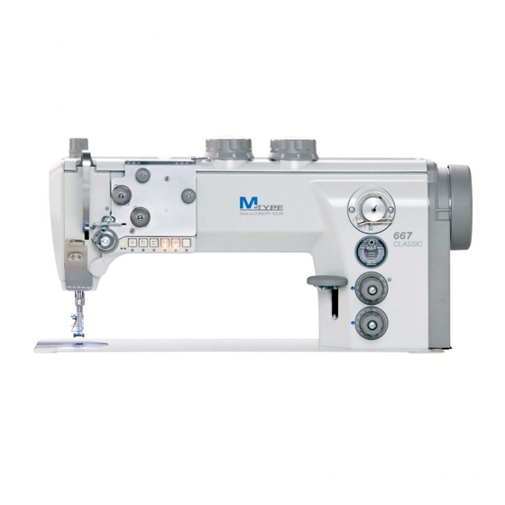
Product description 2.1 Product description The Dürkopp Adler 667 is a special sewing machine for first-class single- needle decorative seams in light to medium-heavy material. It is a single-needle flatbed double-backstitch machine with lower conveyor, needle transport and alternating upper foot conveyor. - Page 8 2.3.1 Technical data for subclasses Subclasses Type of stitch Backstitch 301 Looper type horizontal, XL large, bobbin Ø 26 mm Looper type horizontal, XL oversized, bobbin Ø 32 mm Electromagnetic thread trimmer Electropneumatic seam bartacking and sewing foot lift Switchable thread tension 2 stitch lengths, can be switched electropneumatically 2 stroke heights with knee switch, can be switched elec- tropneumatically...
-
Page 9: Optional Equipment
2.4 Optional equipment For the sewing machine 667 the following optional equipment is available: Subclasses Order no. Optional equipment 9780 000108 WE-8 maintenance unit for optional pneumatic equipment 0797 003031 Pneumatic connection pack. For connecting stands to the main- tenance unit... -
Page 11: Operation
Operation 3.1 Threading the needle thread Caution: Risk of injury! Switch off the main switch! The needle thread should only be threaded when the sewing machine is switched off. Fig. 1 Fig. 2 – Place the thread reel on the thread stand and guide the needle thread through the unwinder arm. -
Page 12: Adjusting The Needle-Thread Tension
3.2 Adjusting the needle-thread tension Fig. 3 Fig. 4 Fig. a: Correct thread interlacing in the centre of the mate- rial Fig. b: Needle-thread tension too strong hook-thread tension too weak Fig. c: Needle-thread tension too strong hook-thread tension too weak... -
Page 13: Function Of The Main Thread Tension And The Supplementary Thread Tension In Relation To The Sewing Foot Lift For Subclass 667-180312 And 667-180322
3.2.1 Function of the main thread tension and the supplementary thread tension in rela- tion to the sewing foot lift for subclass 667-180312 and 667-180322 Button 1 (see chapter 3.15) on the machine's keypad can be used to activate or deactivate the supplementary thread tension at any time. Parameter F-299 must be set to "1"... -
Page 14: Function Of Supplementary Thread Tension In Relation To The Sewing Foot Lift And The Speedomat For Subclass 667-180312 And 667-180332
3.2.2 Function of supplementary thread tension in relation to the sewing foot lift and the Speedomat for subclass 667-180312 and 667-180332 Button 1 (see chapter 3.15) on the machine's keypad can be used to activate or deactivate the supplementary thread tension at any time. Parameter F-255 must be set to "7"... -
Page 15: Opening The Thread Tension
Subclasses 667-180112, 667-180132, 667-180312, 667-180332 The thread tension is automatically opened when trimming the thread. 3.4 Turning the supplementary thread tension on and off for subclasses 667-180312 and 667-180332 Fig. 5 The supplementary tension can be switched on and off with lever 1. -
Page 16: Adjusting The Thread Regulator
3.5 Adjusting the thread regulator Fig. 6 Caution: Risk of injury! Switch off the main switch. The thread regulator may only be adjusted with the sewing machine switched off. The thread regulator 1 controls the quantity of needle thread required for stitch formation. -
Page 17: Winding On The Hook Thread
3.6 Winding on the hook thread Fig. 7 Fig. 8 – Put the thread reel on the thread stand and lead the hook thread through the unwinder arm. – Pull the thread through guide 5, tensioner 3 and guide 4. –... -
Page 18: Changing The Hook-Thread Bobbin
3.7 Changing the hook-thread bobbin Fig. 9 Caution: Risk of injury! Switch off the main switch. The hook-thread bobbin may only be changed with the machine switched off. Remove the empty bobbin. – Set the needle bar at an elevated position. –... -
Page 19: Setting The Hook Thread Tension
3.8 Setting the hook thread tension Fig. 10 Caution: Risk of injury! Switch off the main switch. The hook-thread tension may only be adjusted with the sewing machine switched off. Brake spring The brake spring 1 is responsible for preventing a bobbin overrun when the machine stops and when the hook thread is being cut. -
Page 20: Changing The Needle
3.9 Changing the needle Fig. 11 Fig. 12 Caution: Risk of injury! Switch off the main switch. The needle may only be changed with the sewing machine switched off. – Turn the handwheel until the needle bar 1 reaches its highest posi- tion. -
Page 21: Lifting The Sewing Foot
Subclass 667-180010, 667-180030 – The sewing foot can be lifted mechanically by actuating the knee lever 1. Subclass 667-180112, 667-180312, 667-180312, 667-180322 – The sewing foot can be lifted electropneumatically by actuating the pedal 2. Mechanical sewing foot lift (knee lever) –... -
Page 22: Locking The Sewing Feet In An Elevated Position
3.11 Locking the sewing feet in an elevated position Fig. 14 Fig. 15 – Swivel the lever 1 downwards. The sewing feet are locked in an elevated position. – Swivel the lever 1 upwards. The sewing feet are unlocked. – Lift the sewing feet pneumatically or by using the knee lever. The lever 1 then swivels back to its starting position. -
Page 23: Sewing-Foot Stroke
3.13 Sewing-foot stroke Fig. 16 Fig. 17 Depending on the subclass, the 667 special sewing machine is equipped with two adjusting knobs as standard for adjusting the sewing-foot stroke. Use the left adjusting knob 2 to select the standard sewing-foot stroke between 1 and 9 mm. - Page 24 Fig. 18 Subclass Stitch range Sewing-foot stroke max. stitch count [mm] Adjusting knob position [rpm] 667-180010 0 - 6 1 - 3 3000 667-180030 2500 667-180112 2100 667-180132 6 - 9...
-
Page 25: Adjusting The Stitch Length
Fig. 19 Fig. 20 Depending on the subclass, the 667 special sewing machines are equipped with two adjusting knobs. These allow two different stitch lengths to be used when sewing, which can be selected by using button 4 (see chapter 3.15). -
Page 26: Key Pad On The Machine Arm
3.15 Key pad on the machine arm Button Function Supplementary thread tension Illuminated button: Supplementary thread tension is activated. Non-illuminated button: Supplementary thread tension is not activated. 2nd stitch length Illuminated button: large stitch length (upper adjusting knob) is active Non-illuminated button: small stitch length (lower adjusting knob) is active Invoke or suppress the start/final bartack. - Page 27 Fig. 21 Button 7 can be assigned a function by using the screws 6 located underneath the switches. – Select a function. For example: 6 = sew backwards manually. – Press in the screw underneath button 5 and turn 90° clockwise (the slot is vertical).This function can now be activated by using button 5 and button 7.
-
Page 28: Sewing With Machines Using The Efka Dc1550/Da321G Positioning Drive
3.16 Sewing with machines using the Efka DC1550/DA321G positioning drive The DA321G control unit contains all of the required operating elements for switching functions and setting parameters. It is possible to operate without an operating panel, however the seam programming function can no longer be used. The V810 and V820 operating panels can also be connected to the control unit and are available as optional equipment. - Page 29 Fig. 24 Fig. 25 Sewing operation, sewing Operation / Explanation action Prior to sewing – Pedal in rest position.The sewing machine is at a stop.Needle up. Starting position Sewing foot down. – Depress pedal halfway. The sewing foot raises. – Position the material. Position material at seam –...
- Page 30 Fig. 26 Sewing operation, sewing Operation / Explanation action – Press button 3. 2nd stitch length during sewing (maximum stitch length) – Press button 2. Increase the thread tension during the sewing process – Fully depress and hold the pedal.The final bartack is sewn (if acti- At the seam end vated).The threads are cut (if activated)*.The machine stops in the Remove the material...
-
Page 31: Maintenance
Maintenance 4.1 Cleaning and inspection Caution: Risk of injury! Switch off the main switch. The maintenance of the sewing machine must only be done when the machine is switched off. Maintenance work must be carried out no less frequently than the specified intervals (see "operating hours"... - Page 32 Fig. 29 Fig. 30 Maintenance work Operating Explanation to be conducted hours Direct drive – Clean motor fan filter 1 of sewing dust. – Clean motor fan filter 1 – Reinsert the basket and filter. (e.g. with a compressed air gun) Pneumatic system The water level should not rise as far as filter insert 2.
-
Page 33: Oil Lubrication
4.2 Oil lubrication Fig. 31 Fig. 32 Caution: Risk of injury! Oil can cause skin rashes. Avoid prolonged contact with your skin. Wash thoroughly after contact. CAUTION! The handling and disposal of mineral oils is subject to legal regulations. Transfer used oil to an authorised collection point. Protect the environment. - Page 35 Contents Page: Part 2: Installation Instructions Class 667 Scope of delivery ............................General information and transport packaging..................Assembling the stand and table plate....................... Assembling stand MG 55-3 .......................... Completing the table plate for the MG 55-3 stand with direct drive ............
- Page 36 Abb. 1...
-
Page 37: Scope Of Delivery
Scope of delivery The items supplied depend on your order Before setting up the machine please check to make sure all of the required parts are present. This description refers to the special sewing machine whose individual components are delivered directly and completely from Dürkopp Adler –... -
Page 38: Assembling The Stand And Table Plate
Assembling the stand and table plate 3.1 Assembling stand MG 55-3 Fig. 2 – Assemble the stand in accordance with the illustration. – Fasten the pedal 2 to the stand brace 1. – Affix the stand brace 1 to the stand. –... -
Page 39: Completing The Table Plate For The Mg 55-3 Stand With Direct Drive
3.2 Completing the table plate for the MG 55-3 stand with direct drive Fig. 3 – Turn over the table plate 8. – Screw on the cable channel 1. – Screw on the motor control unit 2. – Screw on the power supply unit 3 (optional equipment). –... -
Page 40: Fastening The Table Plate To The Stand
3.4 Fastening the table plate to the stand Fig. 4 – Fasten stand 7 to table plate 2 by using wood screws (6x30). Pre-drill the holes for the wood screws. – Observe the centre mark for the stand (siehe Kapitel 3.2). –... -
Page 41: Adjusting The Working Height
3.5 Adjusting the working height Fig. 5 – The working height is adjustable between 750 and 900 mm (measured to the upper edge of the table plate). – Undo screws 1 on the stand braces. – Adjust the table plate horizontally to the required working height.To prevent tilting, pull out / push in the table plate by the same distance on both sides. -
Page 42: Fitting The Machine Head
3.6 Fitting the machine head Fig. 6 – Fit the machine head 1 into the opening in the table plate. -
Page 43: Attaching The Knee Lever
3.7 Attaching the knee lever Fig. 7 Fig. 8 The knee lever 1 mechanically raises the sewing foot. – Attach the knee lever 1. – Loosen the screws on the joint 4. – Adjust the knee lever so that it can be conveniently operated with the right knee. -
Page 44: Mounting The Control Panel
3.8 Mounting the control panel Fig. 9 Fig. 10 – The machine arm is provided with two threaded holes for attaching the control panel. – Secure the external control panel 3 to the arm by using the mounting bracket 2 and two screws. –... -
Page 45: Fitting The Sewing Light And Sewing Light Bracket (Optional Equipment)
3.9 Fitting the sewing light and sewing light bracket (optional equipment) Fig. 11 Fig. 12 The sewing light 2 is mounted on the arm cover 1. – Unscrew the arm cover 1. – Use a 4.5 mm Ø bit to drill the mounting holes 4. –... -
Page 46: Electrical Connection
Electrical connection 4.1 General Caution! All work on the electrical equipment of this special sewing machine may only be carried out by qualified electricians or other appropriately trained persons. The mains plug must be removed during any work on the electric equipment! 4.2 Establishing equipotential bonding 4.2.1 Machine head... -
Page 47: Knee Switch
4.2.2 Knee switch Fig. 15 Fig. 16 – Secure the large eyelet on the earthing cable 1 to the knee switch by using screw 2. – Screw the earthing cable 1 to the control box by using screw 3. -
Page 48: Connecting The Da321G Control Unit
– Insert the lead from the control panel (if present) into socket B776. 4.4 Connecting the knee switch – Insert the knee switch cable 3 into the KN19 socket on the front. – Use the clips 4 to secure the cable 3 in place (667-180312 and 667- 180332 only). -
Page 49: Attaching And Connecting The Sewing Light Transformer (Optional Equipment)
4.5 Attaching and connecting the sewing light transformer (optional equipment) Fig. 19 Caution! The sewing light transformer is directly connected to the mains supply. It is therefore live even when the main switch is switched off. The mains plug must be removed before conducting any work on the sewing light transformer, e.g. -
Page 50: Connecting The Sewing Light Transformer To The Da321G Control Unit
4.5.1 Connecting the sewing light transformer to the DA321G control unit Fig. 20 Fig. 21 – Loosen the 4 screws on the front plate of the control unit. – Remove the front plate. – Push the cable from the back through the cable duct 1 into the control unit. -
Page 51: Connecting The Sewing Light To The Transformer
4.5.2 Connecting the sewing light to the transformer Fig. 22 Fig. 23 – Insert the sewing light's supply cable into machine arm 1. – Pass the connecting cable downwards through the opening in the table plate 2. – Reassemble the valve cap. –... -
Page 52: Setting Machine-Specific Parameters
4.6 Setting machine-specific parameters 4.6.1 General information The functions of the sewing-drive control are determined by the program and the parameter settings. 4.6.2 Autoselect The control unit detects which machine series is connected by measuring the Autoselect resistance in the machine. Autoselect selects control functions and the pre-set parameter values. -
Page 53: Pneumatic Connection
Pneumatic connection Fig. 24 Fig. 25 Fig. 26 Caution! The pneumatic units will only operate properly at a supply pressure of 8 to 10 bar. The special sewing machine’s operating pressure is 6 bar. Pneumatic-connection pack A pneumatic-connection pack for stands with compressed-air maintenance units is available under the Order No. -
Page 54: Lubrication
Lubrication Fig. 27 Fig. 28 Caution: Risk of injury! Oil can cause skin rashes. Avoid prolonged contact with your skin. Wash thoroughly after contact. CAUTION! The handling and disposal of mineral oils is subject to legal regulations. Dispose of used oil at an authorised collection point. Protect the environment. -
Page 55: Sewing Test
Sewing test A sewing test should be carried out when setting-up is complete. – Plug the mains cable into the socket. Caution: Risk of injury! Switch off the main switch. The needle and hook threads may only be threaded with the sewing machine switched off. - Page 58 DÜRKOPP ADLER AG Potsdamer Str. 190 33719 Bielefeld Germany Phone: +49 (0) 521 925 00 E-Mail: service@duerkopp-adler.com www.duerkopp-adler.com...