Table of Contents
Advertisement
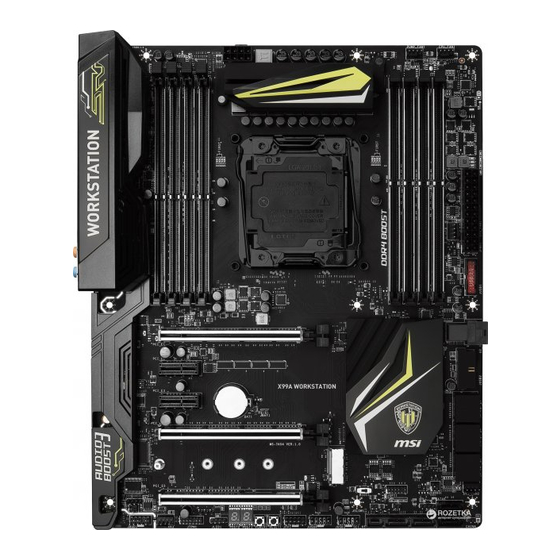
Unpacking
Thank you for buying the MSI
X99A WORKSTATION
motherboard. Check to make sure
®
your motherboard box contains the following items. If something is missing, contact
your dealer as soon as possible.
Drivers & Utilities
Motherboard User
Disc
Guide
Motherboard
I/O Shield
SATA Cable x8
SLI Bridge
RGB LED Extension
Connector x3
Cable x1
SATA Cable Labels
* These pictures are for reference only and may vary without notice.
** The packing contents may vary according to the country you purchased.
1
Unpacking
Advertisement
Table of Contents

Related Manuals for MSI X99A WORKSTATION


Summary of Contents for MSI X99A WORKSTATION
-
Page 1: Unpacking
Unpacking Thank you for buying the MSI X99A WORKSTATION motherboard. Check to make sure ® your motherboard box contains the following items. If something is missing, contact your dealer as soon as possible. Drivers & Utilities Motherboard User Disc Guide... -
Page 2: Safety Information
Safety Information The components included in this package are prone to damage from electrostatic discharge (ESD). Please adhere to the following instructions to ensure successful computer assembly. Ensure that all components are securely connected. Loose connections may cause the computer to not recognize a component or fail to start. Hold the motherboard by the edges to avoid touching sensitive components. -
Page 3: Quick Start
Quick Start Preparing Tools and Components Intel LGA 2011-3 CPU ® CPU Fan Thermal Paste DDR4 Memory Power Supply Unit Chassis SATA Hard Disk Drive Graphics Card SATA DVD Drive A Package of Screws Phillips Screwdriver Quick Start... -
Page 4: Installing A Processor
Installing a Processor Quick Start... -
Page 5: Installing Ddr4 Memory
Installing DDR4 memory Quick Start... -
Page 6: Connecting The Front Panel Header
Connecting the Front Panel Header HDD LED + Power LED + HDD LED - Power LED - Reset Switch Power Switch Reset Switch Power Switch JFP1 Reserved No Pin JFP1 HDD LED - HDD LED HDD LED + POWER LED - POWER LED POWER LED + Quick Start... -
Page 7: Installing The Motherboard
Installing the Motherboard Quick Start... -
Page 8: Installing Sata Drives
Installing SATA Drives Quick Start... -
Page 9: Installing A Graphics Card
Installing a Graphics Card Quick Start... -
Page 10: Connecting Peripheral Devices
Connecting Peripheral Devices Quick Start... -
Page 11: Connecting The Power Connectors
Connecting the Power Connectors JPWR1 JPWR2 Quick Start... -
Page 12: Power On
Power On Quick Start... -
Page 13: Table Of Contents
Contents Unpacking ......................1 Safety Information ....................2 Quick Start ......................3 Preparing Tools and Components ................3 Installing a Processor ..................... 4 Installing DDR4 memory ..................5 Connecting the Front Panel Header ............... 6 Installing the Motherboard ..................7 Installing SATA Drives..................... - Page 14 BIOS1: Multi-BIOS Switch ..................43 POWER1, RESET1: Power Button, Reset Button ..........44 JBAT1: Clear CMOS (Reset BIOS) Jumper ............44 JSLOW1: Slow Mode Booting Jumper ..............45 LED Status Indicators ..................46 LED Status Table....................46 Debug Code LED ....................47 BIOS Setup ......................
-
Page 15: Specifications
Specifications Supports New Intel Core™ i7 Processor Extreme Edition ® for LGA2011-3 Socket Supports Intel Turbo Boost Max Technology 3.0* ® * This function will be supported depend on the CPU. Chipset Intel X99 Chipset ® 8x DDR4 memory slots, support up to 128GB Supports DDR4 3333(OC)/ 3200(OC)/ 3000(OC)/ 2933(OC)/ ƒ... - Page 16 Continued from previous page Intel X99 Chipset ® 10x SATA 6Gb/s ports (2 ports from SATAe port) SATA1~6 support RAID 0, RAID 1, RAID 5 and RAID 10 ƒ SATA7~10 only support IDE mode and AHCI mode ƒ 1x M.2 slot (Key M) For 40-lanes CPU, it supports up to PCIe 3.0 x4 and SATA ƒ...
- Page 17 Continued from previous page 1x 24-pin ATX main power connector 1x 8-pin ATX 12V power connector 10x SATA 6Gb/s connectors 1x SATA Express connector 1x M.2 slot 1x U.2 port 2x USB 2.0 connectors (supports additional 4 USB 2.0 ports) 2x USB 3.1 Gen1 connectors (supports additional 4 USB 3.1 Gen1 ports) 1x 4-pin CPU fan connector...
- Page 18 Intel Extreme Tuning Utility ® Norton Internet Security Solution ™ Google Chrome ,Google Toolbar, Google Drive ™ CPU-Z MSI GAMING DDR4 BOOST Support Quad-Channel DDR4 Memory Support ƒ Isolated DDR4 Circuit Design ƒ DDR4 XMP Ready ƒ Steel Armor Ready ƒ...
- Page 19 EMI Protection ˜ Humidity Protection ˜ MSI Exclusive Circuit Protection ˜ Features High Temperature Protection ˜ VGA Armor Slot ˜ COMMAND CENTER System Monitor ƒ Smart Fan Control ƒ RAMDISK LIVE UPDATE 6 M-CLOUD CPU-Z MSI GAMING SUPER CHARGER Specifications...
- Page 20 Block Diagram 4 Channel DDR4 Memory Processor PCI Express Bus PCIe x1 slot PCIe x1 slot 1x U.2 1x M.2 4x USB 3.1 Gen1 DMI 2.0 8x USB 2.0 1x SATA Express Switch ASMEDIA X99 PCH ASM1074 4x USB 3.1 Gen1 10x SATA 6Gb/s ASMEDIA PCI Express Bus...
-
Page 21: Rear I/O Panel
Rear I/O Panel Audio Ports USB 3.1 Gen2 PS/2 USB 3.1 Gen2 Type-C USB 2.0 USB 3.1 Gen1 USB 2.0 Clear CMOS USB 3.1 Gen1 Optical S/PDIF-Out Clear CMOS button - Power off your computer. Press and hold the Clear CMOS button for about 5-10 seconds to reset BIOS to default values. -
Page 22: Realtek Hd Audio Manager
Realtek HD Audio Manager After installing the Realtek HD Audio driver, the Realtek HD Audio Manager icon will appear in the system tray. Double click on the icon to launch. Device Selection Advanced Settings Jack Status Application Enhancement Main Volume Connector Strings Profiles... - Page 23 Audio jacks to headphone and microphone diagram Audio jacks to stereo speakers diagram AUDIO INPUT Audio jacks to 7.1-channel speakers diagram AUDIO INPUT Rear Front Side Center/ Subwoofer Rear I/O Panel...
-
Page 24: Overview Of Components
Overview of Components DIMM1 DIMM2 JPWR2 DIMM3 PUMPFAN1 DIMM4 CPUFAN1 CPU Socket DIMM8 DIMM7 DIMM6 DIMM5 SYSFAN1 EZ Debug LED JPWR1 JUSB1 BIOS1 JBAT1 JCI1 PCI_E1 U2_1 PCI_E2 JUSB2 JFP2 PCI_E3 SATA1_2 PCI_E4 SATA3_4 M2_1 SATA7_8 SYSFAN2 PCI_E5 SATA9 SATA10 SE1_65 JAUD1 JUSB3... -
Page 25: Component Contents
Component Contents Port Name Port Type Page BIOS1 Multi-BIOS Switch CPUFAN1,SYSFAN1~3,PUMPFAN1 Fan Connectors CPU Socket LGA2011-3 DIMM1~8 DIMM Slots JAUD1 Front Audio Connector JBAT1 Clear CMOS (Reset BIOS) Jumper JCI1 Chassis Intrusion Connector JFP1, JFP2 Front Panel Connectors JLED1 RGB LED connector JPWR1~2 Power Connectors JSLOW1... -
Page 26: Cpu Socket
Always unplug the power cord from the power outlet before installing or removing the CPU. Please retain the CPU protective cap after installing the processor. MSI will deal with Return Merchandise Authorization (RMA) requests if only the motherboard comes with the protective cap on the CPU socket. -
Page 27: Dimm Slots
DIMM Slots DIMM3 DIMM6 DIMM1 DIMM8 Channel A Channel B Channel D Channel C DIMM4 DIMM5 DIMM2 DIMM7 Memory module installation recommendation DIMM3 DIMM1 DIMM1 DIMM5 DIMM7 DIMM3 DIMM5 DIMM1 DIMM3 DIMM6 DIMM2 DIMM7 DIMM1 Overview of Components... - Page 28 DIMM4 DIMM5 DIMM3 DIMM6 DIMM2 DIMM7 DIMM1 DIMM8 Important Always insert a memory module in the DIMM1 slot first. To ensure system stability for Dual/ Triple/ Quad channel mode, memory modules must be of the same type, number and density. And for every channel, the odd number DIMM slot must to be installed first.
-
Page 29: Pci_E1~5: Pcie Expansion Slots
PCI_E1~5: PCIe Expansion Slots PCI_E1: PCIe 3.0 x16 PCI_E2: PCIe 2.0 x1 PCI_E3: PCIe 2.0 x1 PCI_E4: PCIe 3.0 x16 PCI_E5: PCIe 3.0 x8 Important For a single PCIe x16 expansion card installation with optimum performance, using the PCI_E1 slot is recommended. When adding or removing expansion cards, always turn off the power supply and unplug the power supply power cable from the power outlet. - Page 30 Multiple graphics cards installation recommendation x16*/ x8** x16*/ x8** * Only for the CPU with 40 PCIe lanes support. ** Only for the CPU with 28 PCIe lanes support. Overview of Components...
- Page 31 Installing SLI graphics cards For power supply recommendations for SLI configurations, please refer to the user guide of your graphics card to make sure you meet all the system requirements. To install SLI graphics cards: Turn off your computer and disconnect the power cord, install two graphics cards into the PCI_E1 and PCI_E4 slots.
-
Page 32: Sata1~10: Sata 6Gb/S Connectors
SATA1~10: SATA 6Gb/s Connectors These connectors are SATA 6Gb/s interface ports. Each connector can connect to one SATA device. SATA2 SATA1 SATA4 SATA3 SATA8 SATA7 SATA9 SATA6 SATA10 SATA5 SE1_65: SATAe Connector This connector is a SATAe (SATA Express) interface port. Each SATAe connector can be used with a single SATAe device or two legacy SATA devices. -
Page 33: M2_1: M.2 Slot (Key M)
M2_1: M.2 Slot (Key M) Important Intel RST only supports PCIe M.2 SSD with UEFI ROM, ® does not support Legacy ROM. The M.2 PCIe SSD can only operate up to PCIe 2.0 x2 speed on the motherboard with 28-lanes CPU. Installing M.2 module Remove the screw from the base screw. -
Page 34: U2_1: U.2 Connector
U2_1: U.2 Connector This connector is a U.2 interface port. Each connector can connect to one PCIe 3.0 x4 NVMe storage device. Installing U.2 SSD Connect the U.2 cable to the U.2 connector on the motherboard. Connect the U.2 cable to the U.2 SSD. Connect the U.2 cable to power adapter cable. - Page 35 M.2, SATAe & SATA combination table Available SATA/ SATAe connectors 40-lanes 28-lanes M2_1 SATA Empty PCIe SATA Empty PCIe * ─ ✓ ✓ ─ ✓ ─ SE1_65 ✓ ✓ ✓ ✓ ✓ ✓ SATA1 ✓ ✓ ✓ ✓ ✓ ✓ SATA2 ✓...
- Page 36 M.2 slots with examples of various combination possibilities For 40-lans CPU 1xM.2 PCIe + 10xSATA 1xM.2 PCIe + 1xSATAe + 8xSATA PCIe PCIe SATA9 SATA9 SATA6 SATA5 SATAe SATA10 SATA10 1xM.2 SATA + 8xSATA SATA SATA9 SATA10 For 28-lans CPU 1xM.2 SATA + 8xSATA 1xM.2 PCIe + 8xSATA SATA...
-
Page 37: Jpwr1~2: Power Connectors
JPWR1~2: Power Connectors These connectors allow you to connect an ATX power supply. JPWR2 Ground +12V Ground +12V Ground +12V Ground +12V +3.3V +3.3V +3.3V -12V Ground Ground PS-ON# Ground Ground Ground JPWR1 Ground Ground PWR OK 5VSB +12V +12V +3.3V Ground Important... -
Page 38: Jfp1, Jfp2: Front Panel Connectors
JFP1, JFP2: Front Panel Connectors These connectors connect to the switches and LEDs on the front panel. JFP1 HDD LED + Power LED + HDD LED - Power LED - Reset Switch Power Switch Reset Switch Power Switch Reserved No Pin Speaker - Buzzer + JFP2... -
Page 39: Jtpm1: Tpm Module Connector
However, when you boot the computer into Windows ® you will need to install the MSI SUPER CHARGER application to turn ON/OFF the ®... -
Page 40: Jusb3~4: Usb 2.0 Connectors
JUSB3~4: USB 2.0 Connectors These connectors allow you to connect USB 2.0 ports on the front panel. USB0- USB1- USB0+ USB1+ Ground Ground No Pin Important Note that the VCC and Ground pins must be connected correctly to avoid possible damage. -
Page 41: Cpufan1,Sysfan1~3,Pumpfan1: Fan Connectors
CPUFAN1,SYSFAN1~3,PUMPFAN1: Fan Connectors Fan connectors can be classified as PWM (Pulse Width Modulation) Mode and Voltage Mode. PWM Mode fan connectors provide constant 12V output and adjust fan speed with speed control signal. Voltage Mode fan connectors control fan speed by changing voltage. -
Page 42: Jaud1: Front Audio Connector
JAUD1: Front Audio Connector This connector allows you to connect audio jacks on the front panel. MIC L Ground MIC R Head Phone R MIC Detection SENSE_SEND No Pin Head Phone L Head Phone Detection JCI1: Chassis Intrusion Connector This connector allows you to connect the chassis intrusion switch cable. Normal Trigger the chassis intrusion event... -
Page 43: Bios1: Multi-Bios Switch
When BIOS updating fails or causes the computer non-bootable, you can recover the failed BIOS by the steps below. Before recovering, please download the latest BIOS file that matches your motherboard model from MSI website. And then save the BIOS file to the root of the USB flash drive. -
Page 44: Power1, Reset1: Power Button, Reset Button
POWER1, RESET1: Power Button, Reset Button The Power / Reset button allows you to power on / reset the computer. Reset button Power button JBAT1: Clear CMOS (Reset BIOS) Jumper There is CMOS memory onboard that is external powered from a battery located on the motherboard to save system configuration data. -
Page 45: Jslow1: Slow Mode Booting Jumper
JSLOW1: Slow Mode Booting Jumper This jumper is used for LN2 cooling solution, that provides the extreme overclocking conditions, to boot at a stable processor frequency and to prevent the system from crashing. Normal Enabled (default) (Please enable this jumper during BIOS POST.) Important Users will try extreme low temperature overclocking at their own risks. -
Page 46: Led Status Indicators
LED Status Indicators EZ Debug LED: DRAM BOOT XMP LED BIOS B LED BIOS A LED Debug Code LED LED Status Table LED Status Description Light CPU is not detected or fail DRAM Light Memory is not detected or fail EZ Debug LED Light GPU is not detect or fail... -
Page 47: Debug Code Led
Debug Code LED The Debug Code LED displays progress and error codes during and after POST. Refer to the Debug Code LED table for details. Hexadecimal Character Table Hexadecimal Debug Code 0 1 2 3 4 5 6 7 8 9 A B C D E F LED display Boot Phases Security (SEC) –... - Page 48 Post-Memory System Agent initialization PCH DXE Initialization (PCH module 38 - 3A 73 - 77 (System Agent module specific) specific) Post-Memory PCH initialization is started ACPI module initialization Post-Memory PCH initialization (PCH CSM initialization 3C - 3E module specific) 7A - 7F Reserved for future AMI DXE codes DXE IPL is started Boot Device Selection (BDS) phase is...
- Page 49 Configuration Reset (reset of NVRAM Recovery fi rmware image is found settings) Recovery fi rmware image is loaded B8 - BF Reserved for future AMI codes F5 - F7 Reserved for future AMI progress codes DXE Error Codes Recovery Error Codes CPU initialization error Recovery PPI is not available System Agent initialization error...
-
Page 50: Bios Setup
Press Delete key, when the Press DEL key to enter Setup Menu, F11 to enter Boot Menu message appears on the screen during the boot process. Use MSI FAST BOOT application. Click on GO2BIOS button and choose OK. The system will reboot and enter BIOS setup directly. -
Page 51: Resetting Bios
Updating BIOS Updating BIOS with M-FLASH Before updating: Please download the latest BIOS file that matches your motherboard model from MSI website. And then save the BIOS file into the USB flash drive. Updating BIOS: Press Del key to enter the BIOS Setup during POST. -
Page 52: Ez Mode
EZ Mode At EZ mode, it provides the basic system information and allows you to configure the basic setting. To configure the advanced BIOS settings, please enter the Advanced Mode by pressing the Setup Mode switch or F7 function key. XMP switch Setup Mode switch Screenshot... - Page 53 OC GENIE 4 switch - click on the center button to turn the OC GENIE function on or off. Important Please don’ t make any changes in OC menu and don’ t load defaults to keep the optimal performance and system stability after activating the OC GENIE function. Favorites - press any Favorites tab or the F3 key to enter Favorites menu.
-
Page 54: Advanced Mode
Advanced Mode Press Setup Mode switch or F7 function key can switch between EZ Mode and Advanced Mode in BIOS setup. XMP switch Setup Mode switch Screenshot Favorites Language System information OC GENIE 4 switch Boot device priority bar BIOS menu BIOS menu selection selection... -
Page 55: Settings
SETTINGS System Status System Date Sets the system date. Use tab key to switch between date elements. The format is <day> <month> <date> <year>. <day> Day of the week, from Sun to Sat, determined by BIOS. Read-only. <month> The month from Jan. through Dec. <date>... - Page 56 fAbove 4G Decoding [Disabled] Enables or disables 64-bit capable devices to be decoded in above 4G address space. It is only available if the system supports 64-bit PCI decoding. fPEG X - PCI_EX-Gen X [Auto] Sets PCI Express protocol of PCIe x16 slots for matching different installed devices. [Auto] This item will be configured automatically by BIOS.
- Page 57 fIpv4 PXE Support [Enabled] When Enabled, the system UEFI network stack will support Ipv4 protocol. This item will appear when Network Stack is enabled. [Enabled] Enables the Ipv4 PXE boot support. [Disabled] Disables the Ipv4 PXE boot support. fIpv6 PXE Support [Enabled] When Enabled, the system UEFI network stack will support Ipv6 protocol.
- Page 58 fEHCI Hand-off [Enabled] Enables or disables EHCI hand-off support for the operating system without EHCI hand-off feature. fLegacy USB Support [Enabled] Sets Legacy USB function support. [Auto] The system will automatically detect if any USB device is connected and enable the legacy USB support. [Enabled] Enable the USB support under legacy mode.
- Page 59 Fast Boot [Disabled] MSI Fast Boot is the fastest way to boot the system. It will disable more devices to speed up system boot time which is faster than the boot time of Fast Boot. [Enabled] Enables the MSI Fast Boot function to speed up booting time. And the following Fast Boot field will be disabled and fixed.
- Page 60 fResume By RTC Alarm [Disabled] Disables or enables the system wake up by RTC Alarm. [Enabled] Enables the system to boot up on a scheduled time/ date. [Disabled] Disables this function. fDate (of month) Alarm/ Time (hh:mm:ss) Alarm Sets RTC alarm date/ Time. If Resume By RTC Alarm is set to [Enabled], the system will automatically resume (boot up) on a specified date/hour/minute/second in these fields (using the + and - keys to select the date &...
-
Page 61: Boot
Intel ( R ) Ethernet Connection I218-(MAC Shows driver information and configuration of the ethernet controller parameter. Intel ( R ) Ethernet Connection I210-(MAC Shows driver information and configuration of the ethernet controller parameter. Boot Sets the sequence of system boot devices. Full Screen Logo Display [Enabled] Enables or disables to show the full screen logo while system POST. -
Page 62: Save & Exit
Password Check [Setup] Selects a condition that will request the password. [Setup] A password will be requested for entering the BIOS Setup. [Boot] A password will be requested for booting the system. Password Clear [Enabled] Enables or disables the clear CMOS behavior to clear a set password. [Enabled] The password will be erased after clear CMOS. - Page 63 Important Overclocking your PC manually is only recommended for advanced users. Overclocking is not guaranteed, and if done improperly, it could void your warranty or severely damage your hardware. If you are unfamiliar with overclocking, we advise you to use OC GENIE 4 function for easy overclocking.
- Page 64 CPU Ratio Mode [Dynamic Mode]* Selects the CPU Ratio operating mode. This item will appear when you set the CPU ratio manually. [Fixed Mode] Fixes the CPU ratio. [Dynamic Mode] CPU ratio will be changed dynamically according to the CPU loading.
- Page 65 CPU Base Clock Apply Mode [Auto]* Sets the applying mode for adjusted CPU base clock. [Auto] This setting will be configured automatically by BIOS. [Next Boot] CPU will run the adjusted CPU base clock at next boot. [Immediate] CPU runs the adjusted CPU base clock immediately. [During Boot] CPU will run the adjusted CPU base clock during boot.
- Page 66 Memory Fast Boot [Auto] Enables or disables the initiation and training for memory every booting. [Auto] The setting will be configured automatically by BIOS. [Enabled] System will completely keep the archives of first intiation and training for memory. So the memory will not be initialed and trained when booting to accelerate the system booting time.
- Page 67 fCPU VRM Over Temperature Protection [Enabled] Enables or disables the CPU VRM over-temperature protection. [Enabled] Sets the temperature limit on CPU VRM for over-temperature protection. The CPU frequency may be throttled when CPU temperature over the specified temperature. [Disabled] Disables this function. fDRAM CH_A/B, CH_C/D Phase Control [Auto] Controls PWM phase proportionally to the DRAM loading.
- Page 68 CPU Voltages control [Auto] These options allows you to set the voltages related to CPU. If set to Auto, BIOS will set these voltages automatically or you can set it manually. DRAM Voltages control [Auto] These options allows you to set the voltages related to memory. If set to Auto, BIOS will set these voltages automatically or you can set it manually.
- Page 69 fLimit CPUID Maximum [Disabled] Enables or disables the extended CPUID value. [Enabled] BIOS limits the maximum CPUID input value to circumvent boot problems with older operating system that do not support the processor with extended CPUID value. [Disabled] Use the actual maximum CPUID input value. fExecute Disable Bit [Enabled] Intel’...
- Page 70 fIntel C-State [Auto] Enables or disables the Intel C-state. C-state is a processor power management technology defined by ACPI. [Auto] This setting will be configured automatically by BIOS. [Enabled] Detects the idle state of system and reduce CPU power consumption accordingly.
- Page 71 fCPU Current Limit (A) [Auto] Sets maximum current limit of CPU package in Turbo Boost mode. When the current is over the specified value, the CPU will automatically reduce the core frequency for reducing the current. fCPU Over Temperature Protection [Auto] Sets the temperature limit on CPU for over-temperature protection.
-
Page 72: M-Flash
M-FLASH provides the way to update BIOS with a USB flash drive. Please down-load the latest BIOS file that matches your motherboard model from MSI website, save the BIOS file into your USB flash drive. And then follow the steps below to update BIOS. -
Page 73: Oc Profile
OC PROFILE Overclocking Profile 1/ 2/ 3/ 4/ 5/ 6 Overclocking Profile 1/ 2/ 3/ 4/ 5/ 6 management. Press <Enter> to enter the sub- menu. fSet Name for Overclocking Profile 1/ 2/ 3/ 4/ 5/ 6 Name the current overclocking profile. fSave Overclocking Profile 1/ 2/ 3/ 4/ 5/ 6 Save the current overclocking profile. -
Page 74: Hardware Monitor
HARDWARE MONITOR Current Temperature & Speed information Fan control field Setting Buttons Voltage display Current Temperature & Speed information Shows the current CPU temperature, system temperature and fans' speeds. Fan control field This motherboard provides a fan speed control feature call Smart Fan. Please check the Smart Fan Mode box to enable the Smart Fan. -
Page 75: Software Description
7/ 8.1/ 10. ® Installing Drivers Start up your computer in Windows 7/ 8.1/ 10. ® Insert MSI Driver Disc into your optical drive. ® The installer will automatically appear and it will find and list all necessary drivers. Click Install button. -
Page 76: Command Center
COMMAND CENTER COMMAND CENTER is an user-friendly software and exclusively developed by MSI, helping users to adjust system settings and monitor status under OS. With the help of COMMAND CENTER, making it possible to achieve easier and efficient monitoring process and adjustments than that under BIOS. In addition, the COMMAND CENTER can be a server for mobile remote control application. - Page 77 CPU Fan CPU Fan control panel provides Smart mode and Manual Mode. You can switch the control mode by clicking the Smart Mode and Manual Mode buttons on the top of the CPU Fan control panel. Manual Mode - allows you to manually control the CPU fan speed by percentage.
- Page 78 OC GENIE 4 OC GENIE 4 provides a specified CPU frequency for overclocking the CPU. Option Buttons - Advanced When click the Advanced button, The Voltage, Fan and DRAM icons will appear. Voltage - allows you to adjust advanced voltage values of CPU and chipset. Fan - allows you to control the system fans speed.
- Page 79 Find the IP address on the SoftAP Management Setting area, and enter the IP address on your MSI COMMAND CENTER APP to link your system. ® Press Refresh on the MSI COMMAND CENTER APP to verify that monitoring and ® OC functions are working properly.
-
Page 80: Live Update 6
LIVE UPDATE 6 LIVE UPDATE 6 is an application for the MSI system to scan and download the latest ® drivers, BIOS and utilities. With LIVE UPDATE 6, you don’ t need to search the drivers on websites, and don’ t need to know the models of motherboard and graphics cards. -
Page 81: Total Installer
Choose Automatic scan, system will automatically scan all the items and search for the latest update files. Or you can choose Manual scan and select the items you wish to scan. Click the Scan button at the bottom. It may take several moments to complete the process. -
Page 82: Shortcut Manager
Login Keys - provides hotkey login function. ƒ MSI Smart Keys - allows you to define hotkeys for MSI Smart Keys. ƒ Hotkey Editor - allows you to create, edit and delete hotkeys. Current Hotkeys - shows all existing hotkeys. - Page 83 Mouse Master Mouse Master provides mouse macro function. You can also use it to change DPI of your mouse. DPI Setting Defalut Button Delay Time Macro Hot Key DPI Hot Key Mouse Action Action List Test Area Clear Button Edit Buttons Load Button Save Button Delay Time - allows you to input delay time and click the Add button to insert a...
-
Page 84: Mystic Light
MYSTIC LIGHT MYSTIC LIGHT allows you to control LED lights on your motherboard and graphics cards. All LED - controls all LEDs on your motherboard and graphics cards. Each LED - separately controls each segment of LEDs on your motherboard. MB Audio - controls the Audio LED light. -
Page 85: M-Cloud
M-CLOUD M-CLOUD is an application of MSI network sharing. It allows you to turn your computer into Wi-Fi AP. It can also transfer files between your MSI computers. Soft AP ON/OFF History Server Information Users & Permissions Server Local Directory... - Page 86 Setting up Soft AP (optional) The Soft AP function is only available for the motherboard with the built-in WiFi module. You can share your network connection to your smartphones, tablets and laptops with the Soft AP function. Important You must have an active network connection and an installed Wi-Fi moudle to enable Soft AP.
- Page 87 Managing User Accounts This section describes how to create/ remove a user account and configure individual access permissions. Click the Users & Permissions button and the Users & Permissions Management window will pop up. Click Add Account button create a new user account. Fill in user’...
-
Page 88: Ramdisk
RAMDISK RAMDISK creates a virtual RAM drive using the available memory in your computer, the performance of the RAMDISK is faster than an SSD and hard drive. RAMDISK allows you to store any temporary information on it. Furthermore, using the RAMDISK will extend your SSD’... -
Page 89: Usb Speed Up
USB SPEED UP Enabling USB SPEED UP can speed up the date transfer rates of the USB storage devices. Setting On/ Off button Display Setting - enables or disables Run USB SPEED UP when windows starts. Default setting is enabled On/ Off button - switches the USB SPEED UP on or off. -
Page 90: Intel ® Extreme Tuning Utility
Intel Extreme Tuning Utility ® Intel Extreme Tuning Utility (Intel XTU) is a simple overclocking software for you to ® tune, test and monitor your system. Tuning Controls Views Settings Help System Navigation Table System System Monitors Graphs Views Settings Help Views - toggles to switche between Monitoring and Show All view. -
Page 91: Raid Configuration
RAID Configuration Below are the different types of a RAID. RAID 0 breaks the data into blocks which are written to separate hard drives. Spreading the hard drive I/O load across independent channels greatly improves I/O performance. RAID 1 provides data redundancy by mirroring data between the hard drives and provides enhanced read performance. - Page 92 Creating s RAID Volume Select option Create RAID Volume and press Enter key. The following screen appears. CREATE VOLUME MENU Name : Volume0 RAID Level : RAID1(Mirror) Disks : Select Disks Strip Size : N / A Capacity : XXX.X GB Sync : N / A Create Volume...
- Page 93 Removing a RAID Volume Here you can delete the RAID volume, but please be noted that all data on RAID drives will be lost. Important If your system currently boots to RAID and you delete the RAID volume in the IRST Option ROM, your system will become unbootable.
-
Page 94: Degraded Raid Array
Important You will lose all data on the RAID drives and any internal RAID structures when you perform this operation. Possible reasons to Reset Disks to Non-RAID could include issues such as incompatible RAID configurations or a failed volume or failed disk. Recovery Volume Options Select option Recovery Volume Options from the main menu screen and press Enter to change recovery volume mode. -
Page 95: Failed Hard Drive Member
Failed Hard Drive Member Power off. Replace the failed hard drive with a new one that is of equal or greater capacity. Reboot the system to IRST Option ROM by press Ctrl + I keys during the POST. Select the port of the destination disk for rebuilding, and then press Enter. MAIN MENU Recovery Volume Options Create RAID Volume... -
Page 96: Troubleshooting
Troubleshooting Lost BIOS password Before sending the motherboard for RMA repair, try to go over troubleshooting Clear the CMOS, but that will cause guide first to see if your got similar you to lose all customized settings in symptoms as mentioned below. the BIOS. -
Page 97: Regulatory Notices
MSI will comply with the product take back requirements at the end of life of MSI-branded products that are sold into the EU. You can return these products to local collection points.