Table of Contents
Advertisement
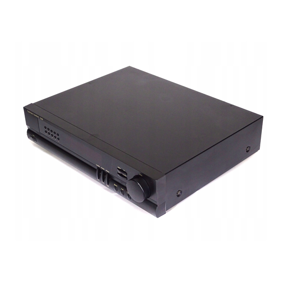
The Harman Kardon
Model TU-940
AM/FM STEREO DIGITAL RDS TUNER
TU 940 RDS
1
2
6
7
Power
LEAKAGE TEST....................................2
SPECIFICATIONS..................................3
CONTROL AND FUNCTIONS..................4
BLOCK DIAGRAM.................................7
DISASSEMBLY PROCEDURES...............8
CIRCUIT DESCRIPTION.......................13
ALIGNMENT PROCEDURES.................16
LOCAL DX
RDS PTY RT CT TA EON TUNED STEREO MONO TUNING P RESET
3
4
5
RF LEVEL STANDBY WIDE NARROW CLOCK TIMERON OFF SLEEPAUTOMEMORY SCAN
8
9
0
CONTENTS
Remote sensor
Auto/Man
RF Mode FM Mode
Band
IF Band
Display
Mode
GENERAL UNIT EXPLODED VIEW.........21
PRINTED CIRCUIT BOARDS.................22
ELECTRICAL PARTS LIST.....................24
IC FUNCTIONAL BLOCK DIAGRAM........32
PACKAGE..........................................33
WIRING DIAGRAM..............................35
SCHEMATIC DIAGRAMS......................36
harman/kardon
80 Crossways Park West, Woodbury, N.Y. 11797
Manual A
Tuning
Display
PTY
Direct
Character
Memory
Tune/Pst
Pst Scan
Parts and Service Office
Printed in Korea
Advertisement
Table of Contents

Related Manuals for Harman Kardon TU-940


Summary of Contents for Harman Kardon TU-940
-
Page 1: Table Of Contents
The Harman Kardon Model TU-940 Manual A AM/FM STEREO DIGITAL RDS TUNER TU 940 RDS Tuning Remote sensor Display LOCAL DX RDS PTY RT CT TA EON TUNED STEREO MONO TUNING P RESET Direct Character RF LEVEL STANDBY WIDE NARROW CLOCK TIMERON OFF SLEEPAUTOMEMORY SCAN... -
Page 2: Leakage Test
LEAKAGE TEST Before returning the unit to the user, perform the model WT 540A or use alternate method as follows: following safety checks: plug the power cord directly into a 230-volt AC 1. Inspect all lead dress to makes certain that leads receptacle ( do not use an isolation transformer for are not pinched or that hardware is not lodged this test.). -
Page 3: Specifications
SPECIFICATION FM SECTION AM SECTION Nominal Limit Nominal Limit Test Condition: 40 kHz DEV., 1kHz Frequency. Test Condition: 400 Hz, 30% Modulation Tuning Range/Step 87.5 MHz –108 MHz/50 kHz Tuning Range/Step Usable Sensitivity (-26dB S/N) 522 kHz – 1611 kHz/9 kHz [ 8.15 dBf [ 12.25 dBf Mono... -
Page 4: Control And Functions
CONTROL AND FUNCTIONS TU 940 RDS Tuning Remote sensor Display LOCAL DX RDS PTY RT CT TA EON TUNED STEREO MONO TUNING P RESET Direct Character RF LEVEL STANDBY WIDE NARROW CLOCK TIMERON OFF SLEEPAUTOMEMORY SCAN Auto/Man RF Mode FM Mode Power Pst Scan Memory... - Page 5 7. MEMORY Use to enter station into the preset memory or to start the Auto Preset Memory function. The memory indicator blinks when the button is pressed. See page 10 for instructions on using the memory system. 8. TUNE/P.SET Press to light PRESET indicator. When the indicator is lit, the TUNING knob can be used to step through the preset stations in ascending or descending order.
- Page 6 13. DIRECT Pressing this button will start the sequence for direct entry of a station’s frequency. After pressing the button simply press the proper Numeric Keys to tune the station. For more information see next page. 14. DISPLAY Press to display current frequency, station name or RDS information. Press again to move to the next item in the following order: If a non-RDS-station is tuned: Frequency, station name (if a name is entered manually).
-
Page 8: Disassembly Procedures
DISASSEMBLY PROCEDURES... -
Page 13: Circuit Description
CIRCUIT DESCRIPTION... - Page 15 Pin Functions Pin No. Configuration Symbol Description Grid signal output for FIP. 1¡- 7 FIP1¡- FIP7 G1¡- G7 +5V Power supply. 9¡- 14 P22¡- P27 N.C. Not used! E. UP Input to detect encoder UP signal. E. DOWN Input to detect encoder DOWN signal. RESET RESET Input to reset CPU.(At "L", it is active)
-
Page 16: Alignment Procedures
ALIGNMENT PROCEDURES 1. Equipment Required • AM Standard Signal Generator (AM SSG.) • Audio Generator • Oscilloscope • Distortion Meter • AC Voltmeter • DC Voltmeter • FM Standard Signal Generator(FM SSG.) • Frequency Counter • Stereo Modulator Note: Remove FM external antenna from terminal when aligning. 2. - Page 17 FM SECTION • Standard Setting of FM Stereo RF Signal Generator. STEREO STANDARD SIGNAL MONAURAL STANDARD SIGNAL Carrier frequency 98 MHz. 98 MHz. Modulation: Audio 1 kHz, 40 kHz deviation. 1 kHz, 40 kHz deviation. Pilot 19 kHz, 7.5 kHz deviation. FM Discriminator Adjustment (NULL and MONO Distortion) Procedure:...
- Page 18 FM Tuned Indication Lighting Level Adjustment Procedure: 1. Tune the set to 98MHz. Set FM SSG. output level to 20dBµ. 2. Adjust VR301 to the point that the “TUNED” indicator begins to illuminate. FM Signal Level Adjustment Procedure: 1. Tune the set to 98MHz. 2.
- Page 19 Procedure: FM Stereo signal VTVM generator output VTVM reading (dB) Connection channel L-CH. L-CH. ⓐ ⓑ R-CH L-CH. Adjust VR 102 minimum reading. R-CH R-CH ⓒ ⓓ L-CH. R-CH Adjust VR 102 for minimum reading. L-CH. Stereo separation: ⓐ - ⓑ R-CH Stereo separation: ⓒ...
- Page 20 AM Tracking Adjustment 1. Set to AM 603 kHz and adjust L 501 to maximize AUDIO output level. 2. Set to AM 1404 kHz and adjust CT 501 to maximize AUDIO output level. 3. Set to AM 999 kHz and adjust L 503 to maximize AUDIO output level. 4.
-
Page 21: General Unit Exploded View
EXPLODED VIEW... -
Page 23: Printed Circuit Boards
PRINTED CIRCUIT BOARD (MAIN) -
Page 24: Electrical Parts List
ELECTRICAL PARTS LIST Ref. No. PART NO. DESCRIPTION ASSEMBLY P.C BOARD MAIN FILTERS CF402 BTCE-00361-107 FILTER-CERAMIC SFE 10.7MM-A-TF21 CF403 BTCE-00361-107 FILTER-CERAMIC SFE 10.7MM-A-TF21 CF404 BTCE-00361-107 FILTER-CERAMIC SFE 10.7MM-A-TF21 CF405 BTCE-00361-107 FILTER-CERAMIC SFE 10.7MM-A-TF21 CF501 BTCE-00510-045 FILTER-CERAMIC LZU450C4N CF503 BTCE-00450-045 FILTER-CERAMIC AHCFM2-450AL CAPACITORS C101... - Page 25 Ref. No. PART NO. DESCRIPTION CAPACITORS C413 CCAT-F223Z-AAF CAPACITOR CERAMIC 0.022uF Z 25V F T C414 CCAT-F223Z-AAF CAPACITOR CERAMIC 0.022uF Z 25V F T C415 CCAT-J473Z-AAF CAPACITOR CERAMIC 0.047uF Z 50V F T C416 CFMT-N473J-GK0 CAPACITOR F/POLYESTR 0.047uF J 100V 8.9x13. T C417 CCAT-J101K-AAB CAPACITOR CERAMIC...
- Page 26 Ref. No. PART NO. DESCRIPTION DIODES D405 DDTS-00070-SO0 DIODE-SI 1SS133 (40V 0.11A) DO-40 T D406 DDTS-00070-SO0 DIODE-SI 1SS133 (40V 0.11A) DO-40 T D407 DDTS-00070-SO0 DIODE-SI 1SS133 (40V 0.11A) DO-40 T D408 DDTS-00070-SO0 DIODE-SI 1SS133 (40V 0.11A) DO-40 T D409 DDTR-00040-T10 DIODE-RECTIFIER 1N4004S(400V 1A 0.6mm) T D410...
- Page 27 Ref. No. PART NO. DESCRIPTION RESISTORS R206 RCFT-E223J-000 RESISTOR-CARBON FILM 22Kohm 1/5W 5% T R208 RCFT-E513J-000 RESISTOR-CARBON FILM 51Kohm 1/5W 5% T R209 RCFT-E513J-000 RESISTOR-CARBON FILM 51Kohm 1/5W 5% T R210 RCFT-E124J-000 RESISTOR-CARBON FILM 120Kohm 1/5W 5% T R211 RCFT-E124J-000 RESISTOR-CARBON FILM 120Kohm 1/5W 5% T R212...
- Page 28 Ref. No. PART NO. DESCRIPTION RESISTORS R433 RCFT-E331J-000 RESISTOR-CARBON FILM 330ohm 1/5W 5% T R434 RCFT-E182J-000 RESISTOR-CARBON FILM 1.8Kohm 1/5W 5% T R435 RCFT-E122J-000 RESISTOR-CARBON FILM 1.2Kohm 1/5W 5% T R436 RCFT-E331J-000 RESISTOR-CARBON FILM 330ohm 1/5W 5% T R437 RCFT-E103J-000 RESISTOR-CARBON FILM 10Kohm 1/5W 5% T R438...
- Page 29 Ref. No. PART NO. DESCRIPTION TRANSISTORS Q401 TRTC-0016G-SD0 TRANSISTOR N-H FREQ KTC3198-GR TO92 Q402 TRSK-0008Y-SD0 FET N-CHANNEL KTK192A-Y TO92M Q403 TRTC-0106Y-SD0 TRANSISTOR N-H FREQ KTC3195Y Q404 TRTC-0106Y-SD0 TRANSISTOR N-H FREQ KTC3195Y Q405 TRTC-0106Y-SD0 TRANSISTOR N-H FREQ KTC3195Y Q406 TRTC-0106Y-SD0 TRANSISTOR N-H FREQ KTC3195Y Q407 TRTC-0106Y-SD0...
- Page 30 Ref. No. PART NO. DESCRIPTION DIODES D910 DDTS-00070-SO0 DIODE-SI 1SS133 (40V 0.11A) DO-40 T LD901 DPLE-00280-RG0 DISPLAY-LED SAM5270 RED/GRN FL901 DPFL-00710-00T DISPLAY-FLUORSCENT CM1918D TUNER INTEGRATED CIRCUITS IC901 ICMP-03720-S20 IC UCOMPUTER UPD7804FGF-169-3B9 QFP80 IC902 ICOP-00210-SD0 IC RESET KIA7042P/F 4.2V TO-92 CONNECTORS CW902 KNCW-00240-4T9 CONNECTOR-WAFER...
- Page 31 Ref. No. PART NO. DESCRIPTION SWITCHS SW908 SWTA-00220-060 SWITCH-TACT SKHV10910(A) 12V 50mA SW909 SWTA-00220-060 SWITCH-TACT SKHV10910(A) 12V 50mA SW910 SWTA-00220-060 SWITCH-TACT SKHV10910(A) 12V 50mA SW911 SWTA-00220-060 SWITCH-TACT SKHV10910(A) 12V 50mA SW912 SWTA-00220-060 SWITCH-TACT SKHV10910(A) 12V 50mA SW913 SWTA-00220-060 SWITCH-TACT SKHV10910(A) 12V 50mA SW914 SWTA-00220-060 SWITCH-TACT...