Advertisement
● PC boards shown are viewed from parts side.
● Parts marked with * require longer delivery time.
● The parts with no reference number or no parts number in the
exploded views are not supplied.
● As regards the resistors and capacitors, refer to the circuit
diagrams contained in this manual.
●
Parts marked with this sign are safety critical
components. They must be replaced with identical
components - refer to the appropriate parts list and
ensure exact replacement.
● Parts of [] mark can be used only with the version designated.
● [US]:U.S.A.[C]:CANADA[SA]:SOUTH AMERICA
NOTES
SERVICE MANUAL
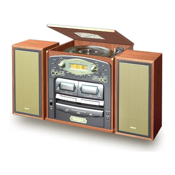
GF-600
Compact Hi-Fi Stereo System
CONTENTS
2 SPECIFICATIONS.......................................
3 ADJUSTMENT AND CHECKS.......................
3-1 AMPLIFIER SECTION................................
3-2 TUNER SECTION.....................................
3-3 CD PLAYER SECTION...............................
3-4 CASSETTE DECK SECTION......................
3-5 TURNTABLE SECTION..............................
4 EXPLODED VIEWS AND PARTS LIST............
5 PC BOARDS AND PARTS LIST.....................
6 WIRING DIAGRAM......................................
2
3
4
4
5
7
8
10
11
21
28
Advertisement
Table of Contents

Related Manuals for Teac GF-600


Summary of Contents for Teac GF-600
-
Page 1: Table Of Contents
SERVICE MANUAL GF-600 Compact Hi-Fi Stereo System NOTES CONTENTS 1 SAFETY INFORAMTION………………………… ● PC boards shown are viewed from parts side. 2 SPECIFICATIONS………………………………… ● Parts marked with * require longer delivery time. 3 ADJUSTMENT AND CHECKS………………….. ● The parts with no reference number or no parts number in the 3-1 AMPLIFIER SECTION……..…………………. -
Page 2: Safety Information
GF-600 1 SAFETY INFORMATION SAFETY INFORMATION This product has been designed and manufactured according to FDA regulations “title 21, CFR, chapter 1, subchapter J based on the Radiation Control for Health and Safety Act of 1986” and is classified as class 1 laser product. There is no hazardous invisible laser radiation during operation because invisible laser radiation emitted inside of this product is completely confined in the protective housings. -
Page 3: Specifications
GF-600 2 SPECIFICATIONS AMPLIFIER Section SPEAKER SYSTEM Section Output Power…………………...………………….……..15W+15W Type.…………………………….……………….2-way bass reflex Input Sensitivity………………..…………….………….…….220mV Impedance…………….……………………….……….…..6 ohms Frequency Response………………………...….…50 to 20,000 Hz GENERAL Power Requirements…..…120V, 60Hz (U.S.A./Canada model) TUNER Section (FM) 120V/230V AC, 50-60Hz (General export model) Frequency Range………………………..…...87.50 to 108.00 MHz Power Consumption………...……………..……..……..……50W... -
Page 4: Adjustment And Checks
GF-600 3 ADJUSTMENT AND CHECKS ● 0 dB is referenced to 1.0V. ● Load impedance: SPEAKERS: 6 ohm (40W or more) PHONES: 1k ohm (1/4W) ● Specified input level: -3dB (AUX) ● VOLUME position: VOL 20 ● Unless specified otherwise,measurements are made in PHONES jack... -
Page 5: Tuner Section
GF-600 TUNER SECTION SPEAKER AUX INPUT GF-600 MAIN PCB C304 C303 FIG 3-2 Adjustment locations 3-2-1 AM TUNER SIGNAL GENERATOR SETTING MEASURING ITEM GF-600 ADJUSTMENTS POINTS,RESULT Audio Modulation Frequency Output 1710kHz VT 8.0V 1.Voltage adjustment 530kHz Check VT 0.9V 2.IFT... - Page 6 GF-600 AM signal generator GF-600 PHON AC voltmeter 1k ohm AM Loop 1k ohm Antenna 60cm Fig.3-3 3-2-2 FM TUNER SIGNAL GENERATOR SETTING MEASURING ITEM GF-600 ADJUSTMENTS POINTS,RESULT Audio Modulation Frequency Output 108.0MHz VT 8.0V 1.Voltage adjustment 87.5MHz Check VT 2.4V 2.IFT...
-
Page 7: Cd Player Section
GF-600 CD PLAYER SECTION 3-3-1 ADJUSTMENT ● Set all of the adjustment volumes to the center position. ● Use an oscilloscope that has a bandwidth greater than 40MHz. ● Use MCD-111 test disc. A. EF balance adjustment 1. Connect the probe to P1 or J126(TE) and the probe ground to P2 or J154(VC). -
Page 8: Cassette Deck Section
GF-600 3-3-2 Audio performance DISC ITEM SPECIFICATIONS REMARKS TRACK No. FREQUENOY/LEVEL 1.Output level 1KHz/0dB 6 ±3dB 2.Harmonic 1KHz/0dB 0.5% or less distortion 3.Frequency Reference level: 100Hz,20KHz/0dB +1, -3dB response 1KHz 4.S/N ratio -∞dB 50dB or better CASSETTE DECK SECTION Before performing adjustments and checks clean and demagnetize the entire tape path. - Page 9 GF-600 3-4-2 PLAYBACK PERFORMANCE PLAYBACK MEASURING ITEM TEST TAPE ADJUSTMENTS REMARKS FREQUENCY POINTS,RESULT Maximum output MTT-25702 8KHz Azimuth screw 1.Head azimuth level at L/R-ch Fig.3-7 adjustment Phase:within 45° MTT-25702 250Hz Check (Fig.3-8) Reference output Dolby B type 2.Playback MTT-150C Check -4 ±3dB...
-
Page 10: Turntable Section
GF-600 SPEAKER AUX INPUT GF-600 MAIN PCB C304 C303 FIG 3-9 Adjustment locations 3-5 TURNTABLE SECTION CN501 CW503 CN502 SFRN502 SFRN501 SFRN503 FIG 3-10 TURNTABLE HP-4005 Adjustment Wow & Flutter ITEM Speed Adjustment point Number. < 0.35% NO.3 SFR502 3000Hz ±30Hz... - Page 12 GF-600 EXPLODED VIEW-1 REF. NO PARTS NO. DESCRIPTION REMARKS 1 – 1 010-G6000000 NAME PLATE 1 – 2 001-G6000000 FRONT PANEL 1 – 3 007-G6000100 CASS WINDOW(A) 1 – 4 005-G6000000 CASS DOOR(A) 1 – 5 005-28000001 CASS HOLDER 1 – 6...
- Page 14 GF-600 EXPLODED VIEW-2 REF. NO PARTS NO. DESCRIPTION REMARKS 2 – 1 FRONT PANEL ASS’Y 2 – 2 011-28000600 PANEL BKT 2 – 3 006-G6000000 CD DOOR 2 – 4 022-44022033 SCREW Ø4x22MM PWM BLK HD 2 – 5 022-92006033 SCREW Ø2x6MM CM BLK HD...
- Page 16 GF-600 EXPLODED VIEW-3 REF. NO PARTS NO. DESCRIPTION REMARKS 3 – 1 FRONT PANEL ASS’Y 3 – 2 016-G6000000 WOODEN CABINET ASS’Y 3 – 3 004-M9700000 SPEED SW. KNOB 3– 4 010-M9700000 SPEED SW. COVER 3 – 5 100-F1802030 PHONO SPEED SW. PCB ASS’Y 3 –...
- Page 18 GF-600 EXPLODED VIEW-4 REF. NO PARTS NO. DESCRIPTION REMARKS 4 – 1 020-10000200 E-RING ( 5.0M/M ) 4 – 2 037-10000000 RUBBER A 4 – 3 010-10000300 PLATTER 4 – 4 033-17001006 BELT Ø170 x 0.6 x 5MM 4 – 5...
- Page 20 GF-600 EXPLODED VIEW-5 REF. NO PARTS NO. DESCRIPTION REMARKS 5 – 1 TRAY ROULETTE 5 – 2 GEAR ROULETTE 5 – 3 SENSOR PCB ASS’Y 5 – 4 SHEET MOTOR 5 – 5 GEAR WORM 5 – 6 TRAY DISC 5 –...
-
Page 21: Pc Boards And Parts List
GF-600 7 PC BOARD AND PARTS LIST MAIN PCB ASSY MAIN PCB ASSY REF. NO PARTS NO. DESCRIPTION REF.NO PARTS NO. DESCRIPTION 100-G6002010 10W MAIN PCB ASSY L6,7 095-00100001 INDUCTOR 10UH 0.5W (AL0305-1OOK) 062-G6000010 MAIN PCB 078-08450351 FM BPF COIL Ø4.5MMx3.5TxØ0.8MM... - Page 23 GF-600 CD PCB ASSY CD PCB ASSY REF. NO PARTS NO. DESCRIPTION REF.NO PARTS NO. DESCRIPTION 100-29302060 CD PCB ASSY IC101,102 075-07291S11 IC:TA7291S 062-29300001 CD PCB IC103 075-02065F31 IC:TA2065F 018-0LT98000 HEAT SINK IC104 075-9284BF31 IC:TC9284BF IC105 075-02092N01 IC:TA2092N C103,124,126,138 072-11000162...
- Page 25 GF-600 FRONT PCB ASSY HEADPHONE/SENSOR PCB ASSY REF. NO PART NO. DESCRIPTION REF. NO PART NO. DESCRIPTION 100-G6002020 062-G6000030 FRONT CONTROL PCB ASS'Y HEADPHONE/SENSOR PCB 062-G6000020 FRONT CONTROL PCB 070-30220505 CERAMIC CAP 0.0022UF 50V Y5P K C2,4,5 070-30220505 CERAMIC CAP 0.002UF 50V Y5P K...
- Page 27 GF-600...
-
Page 28: Wiring Diagram
R-CH 1N4148 220/16 9014C C361 153M C303 2SA733 2200/25 1N4148 FUSE2 1N4148 2SC945 T2A/250V 1N4148 E HD 2SA733 2SC2001L 100K C364 GF-600 MAIN PCB C360 47/16 3.3/50 2SC3402 C362 102M 153M 100/25 153M GF-600 MAIN PCB BIAS OSC Q10 2SC945... - Page 29 IC102 TA7291S IC101 TA7291S R177 18K R151 220 R107 1K5 R105 CW101 C157 C167 C155 R106 CATH C105 EMIT C106 R111 R102 R110 R103 C103 EC 0.47/50 C104 C102 100/16 EC 0.68/50 C101 100/16 R158 GF-600 CD MAIN PCB 10PIN...
- Page 30 D023 D024 1N4148 1N4148 330P VOL-UP SW024 R021 470 SW026 HIGH SPEED-DUBBING SW VOLUME DOWN SW023 GF-600 FRONT CONTROL PCB CW01 CW05 CW03 CW06 CW02 R01 10K SW025 FROM MAIN PCB FROM MAIN PCB FROM MAIN PCB BBS SW FROM MAIN PCB...