Table of Contents
Advertisement
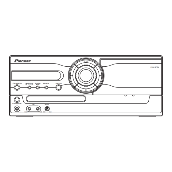
STEREO DVD CASETTE DECK RECEIVER
XV-GX3
THIS MANUAL IS APPLICABLE TO THE FOLLOWING MODEL(S) AND TYPE(S).
Model
Type
XV-GX3
DFLXJ
XV-GX3
DDXJ/RD
XV-GX3
DDXJ/RB
XV-GX3
MTXJ
For details, refer to "Important Check Points for good servicing".
PIONEER CORPORATION
PIONEER ELECTRONICS (USA) INC. P.O. Box 1760, Long Beach, CA 90801-1760, U.S.A.
PIONEER EUROPE NV Haven 1087, Keetberglaan 1, 9120 Melsele, Belgium
PIONEER ELECTRONICS ASIACENTRE PTE. LTD. 253 Alexandra Road, #04-01, Singapore 159936
PIONEER CORPORATION 2005
STANDBY/ON
P.BASS
OPEN/CLOSE
MAIN
Power Requirement
AC 110-120V/220-230V/240V
AC 110-127V/220-230V/240V
AC 110-120V/220-230V/240V
AC 220-230V
4-1, Meguro 1-chome, Meguro-ku, Tokyo 153-8654, Japan
REVERSE
REC/STOP
FUNCTION
MODE
MIC
MIC VOL
SUB
MIN
MAX
XV-GX3
Regional
restriction codes
(Region No.)
3
4
2
3
PUSH OPEN
ORDER NO.
RRV3262
The voltage can be
converted by the
Remarks
following method.
With the voltage selector
With the voltage selector
With the voltage selector
–––––
T-ZZS NOV. 2005 printed in Japan
Advertisement
Table of Contents

Related Manuals for Pioneer XV-GX3


Summary of Contents for Pioneer XV-GX3
- Page 1 PIONEER CORPORATION 4-1, Meguro 1-chome, Meguro-ku, Tokyo 153-8654, Japan PIONEER ELECTRONICS (USA) INC. P.O. Box 1760, Long Beach, CA 90801-1760, U.S.A. PIONEER EUROPE NV Haven 1087, Keetberglaan 1, 9120 Melsele, Belgium PIONEER ELECTRONICS ASIACENTRE PTE. LTD. 253 Alexandra Road, #04-01, Singapore 159936 PIONEER CORPORATION 2005 T-ZZS NOV.
-
Page 2: Safety Information
The interlock mechanism mentioned above becomes invalid in this mode. 2. When the cover is open, close viewing through the objective lens with the naked eye will cause exposure to the laser beam. ∗ : Refer to page 65. XV-GX3... - Page 3 To protect products from damages or failures during transit, the shipping mode should be set or the shipping screws should be installed before shipment. Please be sure to follow this method especially if it is specified in this manual. XV-GX3...
-
Page 4: Table Of Contents
7.1.7 METHOD FOR DIAGNOSING DEGRADATION OF THE LDs ON THE PICKUP ASSY ....72 7.1.8 DVD TROUBLE SHOOTING......................73 7.1.9 ID NUMBER AND ID DATA SETTING ....................76 7.1.10 DISASSEMBLY..........................79 7.2 PARTS..............................89 7.2.1 IC ............................... 89 8. PANEL FACILITIES ............................92 XV-GX3... -
Page 5: Specifications
(excluding DVD-Audio content). For more detailed • is a trademark of Fuji Photo Film Co. Ltd. information on the DualDisc specification, please refer to • is a trademark of DVD Format/Logo the disc manufacturer or disc retailer. Licensing Corporation XV-GX3... -
Page 6: Exploded Views And Parts List
For the applying amount of lubricants or glue, follow the instructions in this manual. (In the case of no amount instructions, apply as you think it appropriate.) 2.1 PACKING SECTION DDXJ/RD only DFLXJ only DFLXJ only MTXJ only Yellow Junction MTXJ only XV-GX3... - Page 7 Service Map (Thai) Not used Not used Not used XRY3005 Polyethylene Bag Not used Not used Not used AHG7031 Warranty Card (Thai) Not used Not used Not used XRY3004 Power Plug Adapter Not used Not used XKM3001 Not used XV-GX3...
-
Page 8: Exterior Section
2.2 EXTERIOR SECTION DFLXJ DDXJ/RB DDXJ/RD only Refer to "2.3 FRONT PANEL SECTION". 9 30 Fans Cleaning paper GED-008 Refer to "2.4 05 LOADER ASSY". XV-GX3... - Page 9 REK1025(T2A) REK1025(T2A) Not used > Fuse (FU1) REK1028(T4A) REK1028(T4A) REK1028(T4A) REK1025(T2A) VS Knob AAD7690 AAD7690 AAD7690 Not used Rear Panel ANC8357 ANC8370 ANC8369 ANC8368 Caution Label VRW2159 VRW1699 VRW1699 VRW1699 Fuse Card Not used Not used Not used AAX2357 XV-GX3...
-
Page 10: Front Panel Section
"2.2 EXTERIOR SECTION ". Refer to "2.2 EXTERIOR SECTION ". Refer to "2.2 EXTERIOR SECTION ". Refer to "2.2 EXTERIOR SECTION ". Refer to "2.2 EXTERIOR SECTION ". Refer to "2.2 EXTERIOR SECTION ". Refer to "2.6 DECK MECHANISM ASSY". XV-GX3... - Page 11 Button Center (PLS) ADD7750 Button L ADD7751 Display Window AAK8303 Deck Door AAN7231 Ratch Spring R ABH7131 Front Panel AMB7904 Damper Assy AXA7052 Pioneer Name Plate VAM1129 LEG Cushion XEB3028 Ratch Mold R XMR3002 Screw with Washer ABA7124 Screw PPZ30P080FNI XV-GX3...
-
Page 12: Loader Assy
Flexible Cable (24P) VDA2008 Screw JGZ17P028FTC Connector Assy 2P VKP2253 Screw VBA1094 Floating Rubber VEB1351 Tray VNL1920 Belt VEB1358 Clamp Magnet VMG1029 Stabilizer VNE2253 Loading Base VNL1917 Float Base 04 VNL1968 Drive Cam VNL1919 Gear Pulley VNL1921 Loading Gear VNL1922 XV-GX3... - Page 13 Rear View Daifree Daifree No. 23 No. 23 GEM1036 GEM1036 Tray Tray Concave of unevenness Concave of unevenness Inner side of a ditch Daifree GEM1036 Top View Bottom View Side of the rib Concave of unevenness Daifree Daifree GEM1036 GEM1036 XV-GX3...
-
Page 14: Traverse Mechanism Assy-S
Stepping Screw DBA1205 NSP 4 Sub Guide Shaft VK1 DLA1941 Spindle Screw VK1(for Service) DBA1252 NSP 5 Joint VK1B DNK4272 NSP 6 Joint Spring VK1 DBK1235 Stepping Motor VK1 DXM1201 NSP 8 Mechanism Frame VK1 DNK4160 Precision Screw VK1 DBA1209 XV-GX3... -
Page 15: Deck Mechanism Assy
DECK MECHANISM ASSY PARTS LIST Mark No. Description Part No. Main Belt FF20B-13A F/R Belt FF19S-31 Plate HD Blk F513-926 Roller Pinch Blk R F514-133 Roller Pinch Blk L F514-134 Clutch Assy Blk F522-063 Motor Main Blk F525-394 PCB Control Blk F567-747 XV-GX3... -
Page 16: Block Diagram And Schematic Diagram
IC5701 BU1924F LINE IN J3001 LINE OUT DECK BLOCK PB/REC HEAD CN2301 Q2301 ERASE HEAD CN2302 RECOUT1 RDSDATA Bias OSC BIAS JA3901 MIC ASSY (2/2) IC3901 (1/2) IC3901 BA4560RF BA4560RF CN3901 MIC ECHO IC3921 M65855FP CN3051 JA3902 MIC BLOCK XV-GX3... - Page 17 Godzzila AMP IC3521,3522 SP OUT LEVEL Detect MS Circuit Circuit MUTE (STBY) Volum JOG S5971 CN5651 CN5901 Blue LED IC5501 PDC-129A-K PDC-129A8-K D5981 D5982 S5961-S5970 4 95 DISPLAY ASSY Remocon V5901 FL Drider IC5902 IC5901 RPM7140 PT6315 Power Supply Block XV-GX3...
-
Page 18: Overall Wiring Connection Diagram And Loab Assy
HALF MODE CN5651 DECK MECHA GNDM 52045-1745 VD+5V (XYM3019) RECF MOTOR RECR CN2301 NoAssign7 B4B-PH-K-S YK56R-AA4N3 ADD7410 (17P FFC) CN2302 NoAssign1 B2B-PH-K-S CN5901 52045-1745 DISPLAY ASSY NoAssign6 (AWU8275) (FL,LED,KEY,IR) FM/AM CN5701 52045-1145 TUNER UNIT (AXX7173) * No schematic diagram XV-GX3... - Page 19 AC CORD 240/220-230/110-120 VNE1948 S101 S102 JA8801 AKX7017 AKX7017 XKP3084 VKB1168 1/4 - MAIN ASSY (AWM8013) (AWM8015) (AWM8016) JA8802 AKP7045 Model XV-GX3 /DFLXJ /DDXJ/RD /MTXJ /DDXJ/RB Singapore Thailand Mexico South Africa Malaysia Middle & Middle East Taiwan South Philippines America Indonesia...
-
Page 20: Dvdm Assy (1/2)
: TRACKING SERVO LOOP LINE : STEPPING SERVO LOOP LINE (C/V) : VIDEO SIGNAL ROUTE (R/Cr) : VIDEO SIGNAL ROUTE(R/Cr) (G/Y) : VIDEO SIGNAL ROUTE(G/Y) (B/Cb) : VIDEO SIGNAL ROUTE(B/Cb) (S_Y) : S VIDEO SIGNAL ROUTE (S_C) : S VIDEO SIGNAL ROUTE XV-GX3... - Page 21 DVDM ASSY (AWM7966) XV-GX3...
-
Page 22: Dvdm Assy (2/2)
3.4 DVDM ASSY (2/2) DVDM ASSY (AWM7966) XV-GX3... - Page 23 (R/Cr) (B/Cb) (R/Cr) : AUDIO SIGNAL ROUTE (C/V) : VIDEO SIGNAL ROUTE (R/Cr) : VIDEO SIGNAL ROUTE(R/Cr) (G/Y) : VIDEO SIGNAL ROUTE(G/Y) (B/Cb) : VIDEO SIGNAL ROUTE(B/Cb) (S_Y) : S VIDEO SIGNAL ROUTE (S_C) : S VIDEO SIGNAL ROUTE XV-GX3...
-
Page 24: Main Assy (1/4)
29.(DTS ON/OFF)STBY FLCE 51.EPROM_CLK VDD2 30.XREADY R5528 FLDATA R5529 GNDU R5530 R5535 VE+5 D5501 R5586 LEVEL 1SS355 120k R5544 RELAY GNDU VE+5 VDVD+12 VPR+8M UTEST VPR+8 STEST SHORT for TEST POINT GNDD CNB25 GNDVDM STBY*2 PCB Binder VKN1256 VEF1040 CN901 XV-GX3... - Page 25 U-COM NOTES ALL CAPACITORS ARE IN µF UNLESS OTHERWISE SPECIFIED CH:CCSRCH*** OTHER:CKSRYB*** TS:CE*****M##-TS AL:CEAL***M##-* (OTHER : CEAT***M##) ALL INDUCTORS ARE IN µH UNLESS OTHERWISE SPECIFIED LAU***J ALL RESISTORS ARE IN UNLESS OTHERWISE SPECIFIED :1/4WPU :1/16W NoAssign1 NoAssign2 (1/2W): RD1/2PM***J XV-GX3...
-
Page 26: Main Assy (2/4)
NOTES L2801 RTD1082 R2805 Q2802 ALL CAPACITORS ARE IN µF 2SC1815(YGR) UNLESS OTHERWISE SPECIFIED L2802 (1/2W) CH:CCSRCH*** LFEA151J YF:CKSRYF*** 0.15mH OTHER:CKSRYB*** R2811 R2809 M:CQMA*** BIAS HA:CQHA*** Q2805 R2815 MB:CQMBA*** Q2806 2SC1815(YGR) 2SC2240(GR) TS:CE*****M##-TS JQ:CEJQ***M##-* AL:CEAL***M##-* GNDB (OTHER : CEAT***M##) XV-GX3... - Page 27 BD3401KS2 GNDA GNDD STBY REC LEVEL Adj. STBY PB LEVEL Adj. U-COM ALL RESISTORS ARE IN UNLESS OTHERWISE SPECIFIED 1/16W 1/4WPU ALL COILS ARE IN µH UNLESS OTHERWISE SPECIFIED LAU***J ALL DIODES ARE 1SS133 UNLESS OTHERWISE SPECIFIED 1SS133 MTZJ*** XV-GX3...
-
Page 28: Main Assy (3/4)
CAUTION : FOR CONTINUED PROTECTION AGAINST D3306 S5688G S5688G RISK OF FIRE. REPLACE ONLY WITH SAME TYPE NO. 491007 MFD, BY LITTELFUSE INK. FOR IC3303. W182 GNDA STBY IC3303 AEK7021 (7A) GNDP GNDS IC3304 STBY GNDA W179 GNDP GNDP GNDS GNDS XV-GX3... - Page 29 Q3621 DTA124EUA VD+5 2SC4081(QR) Q3624 Q3622 R3623 D3624 STBY R3627 6.8k 1SS133 STBY D3622 DAN202K W398 Q3623 Q3620 DTA124EUA DTA124EUA R3628 STBY D3625 D3626 Q3629 R3626 DTC143EUA 3.3k 1SS133 1SS133 Q3628 C3624 DTC124EUA 10/50 1/4, 4/4 XPROTECT GNDSP RECAC XV-GX3...
-
Page 30: Main Assy (4/4)
ONLY /MTXJ ATT7078 VE+5 VUN+5 PROTECT BAIDEN 13.5V IC11 TA7805S VNE1948- 1000p 2SC4081(QR) S1NB60 2SD1858X(QR) GNDD SYSPOW • NOTE FOR FUSE REPLACEMENT SUBAC CAUTION - FOR CONTINUED PROTECTION AGAINST RISK OF FIRE. REPLACE WITH SAME TYPE AND RATINGS OF FUSE. XV-GX3... - Page 31 D5SBA20(B) VPR+8 VD+5 VFL+5 2SB1565(EF) VPR+8 VPR+8M IC42 IC41 NJM78L08A NJM78M05DL1A-TLB GNDD GNDU GLED GNDM MTZJ11B MTZJ7.5C GNDF GNDSP GNDA IC51 TA79012S 2SB1565(EF) VA-12 VF-12 VFDP 1/4, 3/4 XPROTECT DTA124EUA DTC124EUA GNDS VA-12 FLDC+ S5688G FLDC- 2SB1565(EF) GNDSP VFDP XV-GX3...
-
Page 32: Display And Mic Assys
RPM7140-H9 R5962 R5967 R5968 R5969 R5963 R5965 R5964 R5966 1.2k 1.5k 1.8k 3.3k 5.6k 2.7k POWER ON FUNCTION REC/STOP REVERSE P.BASS MODE VE+5 VOL JOG PCB BINDER VEF1040 VLED+12 C5971 GNDU VE+5 0.022 BLUE LED R5981 Q5981 2SC4081(QR) GNDLED XV-GX3... - Page 33 JA3991 UNLESS OTHERWISE SPECIFIED AKN7003- CKSRYB**K50 AMPL AMPL JQ : CEJQ**M** AL : CEAL**M** AT : CEAT**M** GNDHP GNDHP ALL RESISTORS ARE IN L3991 STBY AMPR RS1/16S***J AMPR RS1/10S***J KN3991 GNDHP VNF1084 ALL INDUCTORS ARE IN µH GNDC LAU***J-TA XV-GX3...
-
Page 34: Waveforms
IC201-pin225 [ASPDIF AUDIO DIGITAL SIGNAL] [SPINDLE (WVU)] V: 2V/div. H: 500nsec/div. V: 2V/div. H: 2msec/div. IC401-pin23 [CompositeVideo Out] IC401-pin21 [S VIDEO OUT - Y] V: 1V/div. H: 10µsec/div. V: 1V/div. H: 10µsec/div. IC401-pin26 [S VIDEO OUT - C] V: 1V/div. H: 10µsec/div. XV-GX3... -
Page 35: Pcb Connection Diagram
Resistor array 3-terminal regulator 4.1 LOAB ASSY SIDE A SIDE B LOAB ASSY LOAB ASSY VNP1836-C LOAB PNE-1B1 S101 LOAD+ VWG2279- CN602 C102 LOAD- CN602 VWG2346- C101 CN601 (VNP1836-C) (VNP1836-C) CN601 CN602 CN601 CN601 CN602 CN104 LOADING MOTOR ASSY XV-GX3... -
Page 36: Dvdm Assy
4.2 DVDM ASSY SIDE A SIDE A To STEPPING MOTOR DVDM ASSY To SPINDLE MOTOR CN102 C538 (ANP7527-A) CN104 CN601 XV-GX3... - Page 37 SIDE B SIDE B DVDM ASSY (ANP7527-A) XV-GX3...
-
Page 38: Main Assy
VE+5 W109 W522 SDATA W513 GNDU W521 MDATA W520 SCLK W519 XREADY W512 W526 W523 XRECMUTE W514 W525 W108 W107 W106 UPPER SIDE CN1501 CN3051 CONTACT SIDE CONTACT SIDE CN5501 CN2901 CN2901 CN1501 CN3051 To DECK MECHA CN901 CN3901 XV-GX3... - Page 39 #491007 FOR IC3303 MFD. AWM8016 BY LITTEL FUSE INC. W504 CN3991 CONTACT SIDE CN3051 ATTENTION CONTACT SIDE EN CAS REMPLACEMENT DES FUSIBLES IC3303 N'UTILISER CN5651 QUE LA REFERENCE 491007 DE CHEZ LITTELFUSE INC. CN3051 CN3991 CN5651 (ANP7548-A) CN3901 J3992 CN5901 XV-GX3...
- Page 40 Q3652 Q3653 Q3629 Q3623 Q3628 Q3622 Q3624 Q3621 PRIMARY VA-12 D3622 Q3604 GNDA Q3605 VM+12 Q3606 VA+12 Q3601 Q3602 IC41 VPR+8 VD+5 SECONDARY D3323 VE+5 VUN+8 CMKM-P3X Q5503 CONTACT SIDE CN5651 GNDFL CN3051 CONTACT SIDE CN3991 CN5651 CN3991 CN3051 XV-GX3...
- Page 41 Q3321 Q3625 Q3542 XDVDRST D3321 Q3541 Q5502 TCMODE VDET STEST UTEST VE+5 SDATA IC5401 GNDU MDATA SCLK Q2902 XREADY Q2906 Q2905 XRECMUTE CN1501 CN5501 UPPER SIDE Q2901 CN3051 CONTACT SIDE CONTACT SIDE CN2901 CONTACT SIDE CN3051 CN1501 CN2901 (ANP7548-A) XV-GX3...
-
Page 42: Display Assy
4.4 DISPLAY ASSY SIDE A SIDE A DISPLAY ASSY CN5901 CN5651 L5901 (ANP7549-A) XV-GX3... - Page 43 SIDE B SIDE B DISPLAY ASSY R5965 1.GNDLED 2.VLED+12 3.LED1 4.JOG 5.KEY2 6.KEY1 7.GNDU 8.VFL+5 9.GNDFL 10.REMOCON 11.VE+5 12.FLDC- 13.FLDC+ 14.VFDP 15.FLCS 16.FLCK 17.FLDATA (ANP7549-A) XV-GX3...
-
Page 44: Mic Assy
4.5 MIC ASSY SIDE A SIDE A MIC ASSY CN3051 CN3901 UPPER SIDE CONTACT SIDE CN3991 (ANP7549-A) XV-GX3... - Page 45 SIDE B SIDE B MIC ASSY CN3901 GNDA (ANP7549-A) XV-GX3...
-
Page 46: Pcb Parts List
IC 401 (B,92 ,22 ) DVD VIDEO AMP IC MM1623BF Q 702 (A,27 ,129 ) DIGITAL TRANSISTOR DTC124EUA IC 501 (A,98 ,71 ) D/A CONVERTER PCM1753DBQ > Q 732 (B,22 ,90 ) FET RSQ035P03 > IC 711 (A,33 ,74 ) REGULATOR (1.8V) MM1661JH XV-GX3... - Page 47 R 225 (A,40 ,23 ) CHIP RESISTOR ARRAY RAB4C330J R 423 (B,99 ,21 ) RS1/16S0R0J R 226 (A,43 ,23 ) RS1/16S330J R 424 (B,99 ,23 ) RS1/16S0R0J R 227 (A,44 ,23 ) RS1/16S330J R 425 (B,99 ,25 ) RS1/16S0R0J XV-GX3...
- Page 48 R 905 (A,44 ,128 ) RS1/16S332J C 232 (B,46 ,36 ) CKSRYB104K25 R 906 (A,42 ,126 ) RS1/16S682J C 233 (B,49 ,33 ) CKSRYB104K25 C 234 (B,52 ,33 ) CKSRYB104K25 R 907 (A,46 ,128 ) RS1/16S471J R 908 (A,47 ,128 ) RS1/16S332J XV-GX3...
- Page 49 Q 2304(B,20 ,117 ) TRANSISTOR DTC114TK C 413 (B,84 ,21 ) CKSRYB105K10 C 414 (B,84 ,25 ) CKSRYB105K10 Q 2351(B,67 ,116 ) CHIP DIGITAL TRANS. DTA124EUA C 415 (B,84 ,27 ) CKSRYB104K25 Q 2352(B,57 ,117 ) CHIP TRANSISTOR RN1901 XV-GX3...
- Page 50 (A,228 ,230 ) AC INLET 1P XKP3084 D 2301(A,23 ,111 ) DIODE 1SS133 (A,230 ,208 ) FUSE CLIP AKR7001 D 2302(A,17 ,113 ) DIODE 1SS133 (A,230 ,187 ) FUSE CLIP AKR7001 D 2303(A,26 ,106 ) DIODE 1SS133 (A,315 ,171 ) FUSE CLIP AKR7001 XV-GX3...
- Page 51 R 2102(B,77 ,116 ) RS1/16S124J R 3002(B,66 ,212 ) RS1/16S224J R 2103(B,75 ,116 ) RS1/16S392J R 3003(B,78 ,209 ) RS1/16S182J R 2104(B,74 ,104 ) RS1/16S271J R 3004(B,64 ,208 ) RS1/16S182J R 2105(B,83 ,110 ) RS1/16S333J R 3005(B,76 ,209 ) RS1/16S472J XV-GX3...
- Page 52 R 3341(B,145 ,80 ) RS1/16S333J R 5503(B,98 ,63 ) RS1/16S471J R 3342(B,144 ,84 ) RS1/16S333J R 5504(B,93 ,62 ) RS1/16S104J R 3343(B,154 ,69 ) RS1/16S273J R 5506(B,95 ,62 ) RS1/16S221J R 3344(B,141 ,71 ) RS1/16S273J R 5511(B,80 ,52 ) RS1/16S101J XV-GX3...
- Page 53 CQMBA333J50 R 8853(B,22 ,209 ) CHIP RESISTOR RS1/16S75R0F C 2402(A,47 ,151 ) FILM CAPACITOR CQMBA333J50 R 8863(B,11 ,210 ) CHIP RESISTOR RS1/16S75R0F C 2405(B,37 ,148 ) CKSRYB221K50 R 8873(B,15 ,209 ) CHIP RESISTOR RS1/16S75R0F C 2406(B,45 ,149 ) CKSRYB221K50 XV-GX3...
- Page 54 C 5709(B,29 ,194 ) CKSRYB103K50 C 3056(A,52 ,189 ) CEAT100M50 C 8822(B,27 ,213 ) CCSRCH470J50 C 3057(A,153 ,24 ) CEAT100M50 C 8831(A,39 ,205 ) ELECT. CAPACITOR CEAT102M6R3 C 3059(A,84 ,150 ) CEAT100M50 C 8851(A,21 ,200 ) ELECT. CAPACITOR CEAT102M6R3 XV-GX3...
- Page 55 C 3913(B,48 ,153 ) CKSRYB104K16 C 5911(B,134 ,82 ) CKSRYB223K50 C 5912(B,136 ,74 ) CKSRYB223K50 C 3914(B,46 ,153 ) CCSRCH101J50 C 5913(A,143 ,59 ) CEJQ470M6R3 C 3916(A,44 ,164 ) CEAT2R2M50 C 5915(B,171 ,90 ) CKSRYB103K50 C 3917(B,35 ,155 ) CKSRYB122K50 XV-GX3...
- Page 56 C 3929(B,35 ,172 ) CKSRYB104K16 C 3930(B,39 ,172 ) CKSRYB103K50 C 3931(B,44 ,172 ) CKSRYB472K50 C 3932(B,51 ,175 ) CKSRYB123K50 C 3933(A,37 ,168 ) CEAT101M16 C 3993(B,36 ,90 ) CKSRYB104K16 C 3995(B,42 ,73 ) CKSRYB103K50 C 3996(B,41 ,67 ) CKSRYB103K50 XV-GX3...
-
Page 57: Adjustment
30 s 10s ......................10s 315 Hz –20 dB 12.5 6.3 kHz 10 kHz 315 Hz 14 kHz 10 kHz 8 kHz 4 kHz 2 kHz 1 kHz 63 Hz 40 Hz Fig. 6-1 Test Tape NCT– 112 ( STD-331E) XV-GX3... -
Page 58: Playback And Recording Section
10kHz signal is within 0dBV and 10KHz signals. PLAY from that of the 315Hz signal. VR2802 R ch (see the Note below) Note: Set the 10kHz input signal level to the same value as the 315Hz input signal level of step 1. XV-GX3... - Page 59 VR2801 R2805 VR2802 Q2806 R2803 C2810 L2801 R2815 R5507 W229 W218 C2801 W230 C2803 C2804 W232 Q2802 R5563 C2802 Q2801 BIAS FWD Azimuth REV Azimuth VR2802 VR2801 Adjustment Screw Adjustment Screw (Rch) (Lch) Fig. 6-2 Adjustment and Measurement Points XV-GX3...
-
Page 60: Dvd Section
[Electrical Part] screw screw Electrical adjustments are not required. 6.2.2 JIG AND MEASURING INSTRUMENTS Test mode remote control Screwdriver (large) Screwdriver (medium) TV monitor unit (GGF1381) Screw tight (GYL1001) DVD test disc Precise screwdriver Soldering iron (GGV1025) XV-GX3... -
Page 61: Necessary Adjustment Points
Exchange the Traverse Mechanism point Assy-S Electric point ∗ After adjustment, screw locks Mechanical Ÿ Exchange the Spindle Motor point with the Screw tight. Electric point Exchange PCB Assy Mechanical Exchange PC Board point LOAB and DVDM ASSYS Electric point XV-GX3... -
Page 62: Test Mode
• After going into test mode, if you play back the disc, "DISC-NON" is displayed. • The video signal and the audio signal are outputted during the test mode. • The SKIP key and the SCAN key are effective during the test mode. TEST MODE: OFF POWER GGF1381 Test mode remote control unit XV-GX3... -
Page 63: Mechanism Adjustment
(Refer to "6.2.1 ADJUSTMENT ITEMS AND LOCATION".) Joint 7.5mm Mechanism base • Attach the Traverse Mechanism Assy-S to the 05 LOADER Assy. • Turn it over and attach the joint and the joint spring. • Arrange the flexible cables. (Refer to "7.1.10 DISASSEMBLY".) XV-GX3... - Page 64 90 degrees step till ERROR RATE block error rate becomes around "1E-3" again . CHP/TIM • Record the number of rotation (N1). • Fasten the tangential adjustment screw till the number of rotation becomes Service mode end harf of N1. Best tangential point XV-GX3...
-
Page 65: General Information
: Press the [TEST] (A8-5E) and [4] (A8-04) keys in order, and turn on the laser diode (780n). 3 Release the Test mode • Turn off the power. • Press the [ESC] (A8-5F) key of the remote control unit and reset it. XV-GX3... -
Page 66: Display Specification Of The Test Mode
: [NTSC] PAL system : [PAL] Automatic setting : [AUTO] Scart terminal output [SK – ∗ ∗] (Display only the WY model which can do the output setting of scart terminal.) VIDEO : [00] S-VIDEO : [01] : [02] XV-GX3... -
Page 67: Functional Specification Of The Shortcut Key
• Region confirmation mode (ESC + A.MON [Test mode remote control unit] + "1"-"8" [Test mode remote control unit] keys) After you press the AUDIO key while holding the ESC key pressed and then input the region number, if the number is different from that set in the unit, an error message is displayed, and the tray opens. XV-GX3... -
Page 68: Specification Of The Model Information Display
Display it according to model information set from the FL controller. 2 Region No. 3 Part number 4 ROM version 5 Flash size 6 FL controller version 7 CHIP VERSION 9 Remote control code 0 Key code of Main unit XV-GX3... -
Page 69: Functional Specification Of The Service Mode
%%e -2 : NG 7.0e -4 : NG 3 EDC/ID error history (ID Address, EDC/ID errors, last eight errors) Note: ∗ Error of AV1 is not supported in this player. Indication plan contents Character in bold : Item name : Information display XV-GX3... -
Page 70: Service Test Mode
• Basically, operations in Service Test mode are the same as in Normal mode. However, to indicate that the unit is in Service Test mode, the following are displayed when the functions are changed: [Functions] [FL display] DVD/CD R V C TUNER R V C TAPE R V C LINE R V C XV-GX3... - Page 71 • The maximum countable power-on time is 255H59M (255 hours 59 minutes.) The indication will not advance beyond that. • The accumulated power-on time basically cannot be cleared. Service Test Mode connecting point Connecting point MAIN ASSY SIDE B TCMODE STEST UTEST VE+5 IC5401 GNDU Q2902 Q2906 Q2905 MUTE XV-GX3...
-
Page 72: Method For Diagnosing Degradation Of The Lds On The Pickup Assy
Assy. Measure the voltage between the both ends of R321 or R326 on the DVDM Assy. If the voltage is 0.4 V or higher, the 780-nm LD is degraded. 05SD PICKUP ASSY CN101 DVDM ASSY Front side SIDE A XV-GX3... -
Page 73: Dvd Trouble Shooting
An opening screen is not DVDM Assy displayed on the monitor Check the video signal path between DVD IC (DVDM Assy IC201) and Video circuit after DVD IC (The FL display lights. The video-out terminal (see the block diagram) (IC201) mechanism works.) XV-GX3... - Page 74 DVD IC (IC201) S video signal (IC401-pin 21, pin 26) Video IC (IC401, IC451) RGB video signal (IC401-pin 16, pin 18, pin 20) No sound DVDM Assy Check the waveform (SPDIF: CN901-pin 16). (Picture is normal) DVD IC (IC201) XV-GX3...
- Page 75 Any kind of symptoms (no power, a failure in any of the servo, video and audio systems, etc.) may be (DVDM Assy : IC201) generated, because the DVD processing is performed by a single chip. 64M SDRAM No power. (DVDM Assy : IC202) Block noise is generated during playback. XV-GX3...
-
Page 76: Id Number And Id Data Setting
ID number. 0 0 0 0 0 0 0 0 1 Note: If you press the PLAY button before inputting a 9-digit ID <PLAY> Enter number, the unit returns to Step 2 without doing anything else. Input ID Number ! XV-GX3... - Page 77 (The STOP key is not accepted after all 9 digits have been entered.) [Player's ID Number Setting] ID Number ? 0 0 0 0 0 0 0 0 1 Compare 0 0 0 0 0 0 0 0 1 <PLAY> Enter <STOP> Memory Clear Input ID Number ! XV-GX3...
- Page 78 • Indication when the data have not been set Insert The ID Data Disc ! If no ID data are set after the ID number is changed, the message "NO DATA" displays on FL display after the power is turned on or during Stop mode. XV-GX3...
-
Page 79: Disassembly
If the Tray pops out a little, fully pull it out by hand. Tweezer Rear View Press the STANDBY/ON button to turn on the power. Press the 0 OPEN/CLOSE button to open the Tray. Remove the Tray Panel. Set the Test Disc. Slit Bottom View Tray Panel Test Disc XV-GX3... - Page 80 Released the hook at the right and left side of the Front Panel Assy. MAIN Assy Slide the Heatsink Holder to the Rear Panel side, and take out the Rear Panel and MAIN Assy. Heat Sink Heatsink Holder Rear Panel XV-GX3...
- Page 81 MAIN Assy GGD1309 Set the Front Panel upright, which you took off in the previ- GGD1447 ous procedure, and connect the six cables to CN5651, CN3991, CN3051, CN2901, CN2302, and CN2301 of the DVDM Assy MAIN Assy, respectively. Front Panel XV-GX3...
- Page 82 DVD Main Board diagnosis Remove 4 screws on the DVDM Assy. DVDM Assy Set the DVDM Assy upright. MAIN Assy DISPLAY Assy MIC Assy DVDM Assy XV-GX3...
- Page 83 05 LOADER Assy 05SD Pickup Assy-S Short-circuit point by soldering. Note: After replacement, connect the flexible cable, then remove the soldered joint (open). Disconnect the four connectors. Remove the two screws. Remove the 05 LOADER Assy. 05 LOADER Assy XV-GX3...
- Page 84 Bridge 04 Tray Note when reinserting the tray When reinserting the tray, first align the triangle Drive cam printed on the loading base and the pin of the drive cam, then insert the tray. Front side Loading base Triangle XV-GX3...
- Page 85 Flexible cable Dislodge the two flexible cables from their factory for the spindle motor placement. Front Side Flexible cable for the pickup Bottom view Unhook the four hooks. Traverse Mechanism Assy-S Remove the Traverse Mechanism Assy-S × 2 × 2 XV-GX3...
- Page 86 Adjustment screw Adjustment screw Remove the 05SD Pickup Assy. (skew screw VK1) (skew screw VK1) 05SD Pickup Assy-S Note: Be careful not to lose the adjustment spring (skew spring VK1). Adjustment screw (skew screw VK1) Adjustment spring (skew spring VK1) XV-GX3...
- Page 87 Note: The screw is secured with the silicone adhesive. Make sure to apply the silicone adhesive after reattaching the screw. Joint VK1B Joint spring VK1 Silicone Adhesive GEM1037 Arrangement of the flexible cable for the spindle motor : Conductive surface Hook Front Side Hook Bottom view XV-GX3...
- Page 88 Attach the flexible cable for the pickup to the connector. Pass the flexible cable through the hook. Hook Backing Front Side Bottom View Hook Pass the flexible cable through the hook. Hook Hook Make sure that the cable is loose XV-GX3...
-
Page 89: Parts
Data for FL driver FLCLK Clock for FL driver XREADY Chip select for system bus (to DVD module) XRECMUTE REC OUT MUTE UTEST_CHK UNITCHECK IN for checker UTEST_EEPOK EEPROM CHECK OK for checker RELAY SP RELAY ON/OFF − VSS4 − VDD4 XV-GX3... - Page 90 Data for tuner LSI (RDSPOW) Control power supply of RDS(L:POWER ON) (RDSDATA) Input RDS data TXIDATA Input data from tuner LSI DVDACK Ackknowlegement from DVD MODULE(Interruption 4) TCPULSE Input pulse of TC reel TCMSIN Input MS signa LED1 LED1 XV-GX3...
- Page 91 FLASH writing / On board debugger − FLASHCLK for FLASH writing / On board debugger XDVDRST RESET to DVD MODULE SYSMUTE Control mute of system SYSPOW Control power supply of system VOLCLK Clock for E-vol IC VOLDATA/CE 100 NC XV-GX3...
-
Page 92: Panel Facilities
REC/STOP– Starts/stops recording on the tape deck. FUNCTION Selects the source you want to listen to. Playback / volume control The playback controls are used for playing, pausing, skipping and stopping playback. Turn the middle section to adjust the volume. XV-GX3... - Page 93 R - Right channel only. Use for tracks that have a vocal recorded in the left channel. L R - Use to put a single-channel vocal track into the center of the mix. Tuner indicators - Lights when a broadcast is being received. XV-GX3...
-
Page 94: Remote Control
Input source function select Key controls (SHIFT+ Selects the source you want to listen to; DVD/ CD , TUNER , TAPE or LINE ( SHIFT + TAPE ). Lowers/raises the pitch of the backing track. XV-GX3... - Page 95 DVD MENU . 12 RETURN Press to return to a previous menu screen. 13 CLEAR Clears an entry. MUTE Mutes the volume. DISPLAY Switches between information displays. SLEEP ( SHIFT + DISPLAY ) – Use for setting the sleep timer. XV-GX3...
- Page 96 Position to be cleaned Cleaning tools Pickup leneses Cleaning liquid : GEM1004 Cleaning paper : GED-008 Position to be cleaned Cleaning tools Cassette heads Pinch rollers Cleaning paper : GED-008 Capstans Position to be cleaned Cleaning tools Fans Cleaning paper : GED-008 XV-GX3...