Mitsubishi Electric FR-D700 Instruction Manual
Hide thumbs
Also See for FR-D700:
- Instruction manual (290 pages) ,
- Manual (34 pages) ,
- Installation manuallines (28 pages)
Advertisement
Quick Links
INVERTER
FR-D700
INSTRUCTION MANUAL (BASIC)
FR-D720-0.1K to 7.5K-EA
FR-D740-0.4K to 7.5K-EA
FR-D720S-0.1K to 2.2K-EA
Thank you for choosing this Mitsubishi Inverter.
This Instruction Manual (Basic) provides handling information and precautions for use of the equipment.
Please forward this Instruction Manual (Basic) to the end user.
OUTLINE ...................................................................................1
1
INSTALLATION AND WIRING ...................................................6
2
PRECAUTIONS FOR USE OF THE INVERTER.........................18
3
FAILSAFE OF THE SYSTEM WHICH USES THE INVERTER ...20
4
DRIVE THE MOTOR.................................................................21
5
PARAMETERS .........................................................................28
6
TROUBLESHOOTING ..............................................................33
7
PRECAUTIONS FOR MAINTENANCE AND INSPECTION ........37
8
SPECIFICATIONS ....................................................................39
9
To obtain the Instruction Manual (Applied) and the
Safety stop function instruction manual
Contact where you purchased the inverter, your Mitsubishi sales
representative, or the nearest Mitsubishi FA Center for the following
manuals:
Instruction Manual (Applied) [IB(NA)-0600431ENG]
Safety stop function instruction manual [BCN-A211508-000]
These manuals are required if you are going to utilize functions and
performance.
CONTENTS
700
1
2
3
4
5
6
7
8
9
Advertisement

Related Manuals for Mitsubishi Electric FR-D700


Summary of Contents for Mitsubishi Electric FR-D700
- Page 1 INVERTER FR-D700 INSTRUCTION MANUAL (BASIC) FR-D720-0.1K to 7.5K-EA FR-D740-0.4K to 7.5K-EA FR-D720S-0.1K to 2.2K-EA Thank you for choosing this Mitsubishi Inverter. This Instruction Manual (Basic) provides handling information and precautions for use of the equipment. Please forward this Instruction Manual (Basic) to the end user.
- Page 2 This Instruction Manual (Basic) provides handling information and precautions for use of the equipment. Please forward this Instruction Manual (Basic) to the end user. 2. Fire Prevention This section is specifically about safety matters CAUTION Do not attempt to install, operate, maintain or inspect the Inverter must be installed on a nonflammable wall without inverter until you have read through the Instruction Manual holes (so that nobody touches the inverter heatsink on the...
- Page 3 (2) Wiring (5) Emergency stop CAUTION CAUTION Do not install a power factor correction capacitor or surge A safety backup such as an emergency brake must be suppressor/capacitor type filter on the inverter output provided to prevent hazardous condition to the machine side.
- Page 4 <Abbreviation> /FR-PU07 PU ...........Operation panel and parameter unit (FR-PU04 Inverter..........Mitsubishi inverter FR-D700 series D700 .........Mitsubishi inverter FR-D700 series Pr............Parameter number (Function number of inverter) PU operation ........Operation using the PU (operation panel/FR-PU04/FR-PU07) External operation......Operation using the control circuit signals Combined operation .......Operation using both the PU (operation panel/FR-PU04/FR-PU07) and External...
-
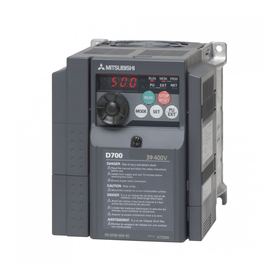
Page 5: Product Checking And Parts Identification
1 OUTLINE Product checking and parts identification Unpack the inverter and check the capacity plate on the front cover and the rating plate on the inverter side face to ensure that the product agrees with your order and the inverter is intact. Inverter model D740 Symbol... - Page 6 Operation panel Operation panel 1.2.1 Names and functions of the operation panel The operation panel cannot be removed from the inverter. Operating status indicator Operation mode indicator Lit or flicker during inverter operation. ∗ PU: Lit to indicate PU operation mode. * Lit: When the forward rotation operation EXT: Lit to indicate External operation mode.
- Page 7 Operation panel 1.2.2 Basic operation (factory setting) Operation mode switchover At powering ON (External operation mode) PU Jog operation mode (Example) PU operation mode Value change and frequency flicker alternately. (output frequency monitor) Frequency setting has been written and completed!! STOP Output current monitor Output voltage monitor...
-
Page 8: Changing The Parameter Setting Value
Operation panel 1.2.3 Changing the parameter setting value Changing Change the Pr. 1 Maximum frequency setting. example Operation Display Screen at power-ON The monitor display appears. PU indicator is lit. Press to choose the PU operation mode. PRM indicator is lit. Press to choose the parameter setting mode. - Page 9 Operation panel 1.2.4 Parameter clear/all parameter clear POINT Set "1" in Pr.CL Parameter clear, ALLC all parameter clear to initialize all parameters. (Parameters are not cleared when "1" is set in Pr. 77 Parameter write selection.) Refer to the extended parameter list on of the Instruction Manual (Applied) for parameters cleared with this operation.
-
Page 10: Installation And Wiring
AC reactor (FR-HAL) DC reactor (FR-HEL) * Braking capability can be improved. (0.4K or more) (Refer to page 17) Inverter (FR-D700) EMC filter (ferrite core) * (FR-BSF01, FR-BLF) EMC filter (ferrite core) R/L1 S/L2 T/L3 Install an EMC filter (ferrite core) - Page 11 Peripheral devices Peripheral devices Check the inverter model of the inverter you purchased. Appropriate peripheral devices must be selected according to the capacity. Refer to the following list and prepare appropriate peripheral devices. Moulded Case Circuit Breaker Magnetic Contactor (MC) (MCCB) ∗1 Motor Reactor...