Table of Contents
Advertisement
final1.html
Table Of Contents
Service Manual
COVER
1 Before Repair and
TOP NEXT
Adjustment
Order No: MD0201021C2
Traverse Deck
6 Caution for AC Mains
Lead
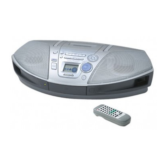
Portable Stereo CD System
9.1 Setting of self-diagnosis
Function
9.1.1 Setting of CD self-
diagnosis mode
RX-ES22E
9.1.2 Setting of cassette
RX-ES22EB
mechanism self-diagnosis
RX-ES22EG
mode
Colour
10 Operation Checks and
(S)..........Silver Type
Main Component Replacement
Procedures
Tape Deck: SG2 Mechanism Series
10.1 Checking Procedure for
each major P.C.B.
Traverse deck: RAE0155Z-1V Mechanism Series
10.1.1 Checking for the
Panel P.C.B.
CD Servo P.C.B.
10.2 Disassembly and
Assembly of Traverse Deck
10.3 Main Component
Replacement Procedures
12 Printed Circuit Board
13 Wiring Connection
Diagram
15 Measurements and
Adjustments
15.1 Tuner Section
16 Type Illustration of IC's,
Transistors and Diodes
17 Terminal Function Of
IC's
18 Parts Location and
Replacement Parts List
(RAA4401-1V)
18.1.1 Deck Mechanism
Parts Location
18.1.2 Deck Mechanism
Parts List
18.2 CD Loading
Mechanism
18.2.1 CD Loading
Mechanism Parts Location
file:///C|/Documents and Settings/eDOK/Рабочий стол/RX-ES22/PVAccel.html (1 of 2)06.11.2005 15:58:32
RADIO
Frequency range
AM
522-1629 kHz (9 kHz steps)
FM
87.5-108 MHz (50 kHz steps)
TAPE RECORDER
Track System
4 track, 2 channel, stereo
Recording system
Erasing system
Multi Pole magnet
Monitor system
Variable sound monitor
Frequency range
Normal position
50-14000 Hz
CD PLAYER
Sampling frequency
Decoding
Beam source
Semiconductor laser (wavelength 780 nm)
No. of channels
2 channel, stereo
Wow and flutter
Below measurable limit
D/A converter
MASH (1 bit DAC)
GENERAL
Power requirement
AC
230-240 V, 50 Hz
Power consumption
Battery
12 V [Eight R20/LR20 (D, UM-1) batteries]
AC bias
44.1 kHz
16 bit linear
23 W
Advertisement
Table of Contents

Related Manuals for Panasonic RX-ES22E


Summary of Contents for Panasonic RX-ES22E
- Page 1 7 Location of Controls 8 The Remote Control Portable Stereo CD System 9 Self Diagnostic Function 9.1 Setting of self-diagnosis Function 9.1.1 Setting of CD self- diagnosis mode RX-ES22E 9.1.2 Setting of cassette RX-ES22EB mechanism self-diagnosis RX-ES22EG mode 9.2 Display Location Colour 9.3 Display Content...
-
Page 2: Accessories
final1.html • Do not use rechargeable type batteries 18.2.2 CD Loading Memory backup for computer/clock 6 V [Four R6/LR6 (AA, UM-3) batteries] Mechanism Parts List • Do not use rechargeable type batteries 18.3 Cabinet Speakers 8 cm 2.7Ω x 2 18.3.1 Cabinet Parts Jacks Location... - Page 3 Settings/eDOK/Рабочий стол/RX-ES22/s0000000000.html Service Manual TOP NEXT Order No: MD0201021C2 Portable Stereo CD System RX-ES22E RX-ES22EB RX-ES22EG Colour (S)..Silver Type Tape Deck: SG2 Mechanism Series Traverse deck: RAE0155Z-1V Mechanism Series RADIO Frequency range 522-1629 kHz (9 kHz steps) 87.5-108 MHz (50 kHz steps)
- Page 4 file:///C|/Documents and Settings/eDOK/Рабочий стол/RX-ES22/s0000000000.html D/A converter MASH (1 bit DAC) GENERAL Power requirement 230-240 V, 50 Hz Power consumption 23 W Battery 12 V [Eight R20/LR20 (D, UM-1) batteries] • Do not use rechargeable type batteries Memory backup for computer/clock 6 V [Four R6/LR6 (AA, UM-3) batteries] •...
-
Page 5: Handling Precautions For
file:///C|/Documents and Settings/eDOK/Рабочий стол/RX-ES22/final1.html Table Of Contents COVER 1 Before Repair and Adjustment 2 Protection Circuitry 3 Accessories 4 Handling Precautions For Traverse Deck 5 Precaution of Laser Diode 6 Caution for AC Mains Lead 7 Location of Controls 8 The Remote Control 9 Self Diagnostic Function 9.1 Setting of self-diagnosis Function 9.1.1 Setting of CD self-diagnosis mode... - Page 6 file:///C|/Documents and Settings/eDOK/Рабочий стол/RX-ES22/final1.html 10.1.1 Checking for the Panel P.C.B. 10.1.2 Checking for Main& CD Servo P.C.B. 10.2 Disassembly and Assembly of Traverse Deck 10.3 Main Component Replacement Procedures 11 Schematic Diagram 12 Printed Circuit Board 13 Wiring Connection Diagram 14 Troubleshooting Guide 15 Measurements and Adjustments 15.1 Tuner Section...
- Page 7 file:///C|/Documents and Settings/eDOK/Рабочий стол/RX-ES22/final1.html 18.2.1 CD Loading Mechanism Parts Location 18.2.2 CD Loading Mechanism Parts List 18.3 Cabinet 18.3.1 Cabinet Parts Location 18.3.2 Cabinet Parts List 18.4 Electrical Parts List 18.5 Packing Materials& Accessories Parts List 18.6 Packaging file:///C|/Documents and Settings/eDOK/Рабочий стол/RX-ES22/final1.html (3 of 3)06.11.2005 15:58:50...
- Page 8 file:///C|/Documents and Settings/eDOK/Рабочий стол/RX-ES22/s0100000000x.html 1 Before Repair and Adjustment TOP PREVIOUS NEXT Disconnect AC power, discharge Power Supply Capacitors C301 through a 10 Ω, 5 W resistor to ground. DO NOT SHORT-CIRCUIT DIRECTLY (with a screw driver blade, for instance), as this may destroy solid state devices.
- Page 9 file:///C|/Documents and Settings/eDOK/Рабочий стол/RX-ES22/s0200000000x.html 2 Protection Circuitry TOP PREVIOUS NEXT The protection circuitry may have operated if either of the following conditions are noticed: No sound is heard when the power is turned on. Stops during a performance. The function of this circuitry is to prevent circuitry damage if, for example, the positive and negative speaker connection wires are “shorted”, or if speaker systems with an impedance less than the indicated rated impedance ofthe amplifier are used.
- Page 10 file:///C|/Documents and Settings/eDOK/Рабочий стол/RX-ES22/s0300000000x.html TOP PREVIOUS NEXT file:///C|/Documents and Settings/eDOK/Рабочий стол/RX-ES22/s0300000000x.html (2 of 2)06.11.2005 15:59:00...
- Page 11 file:///C|/Documents and Settings/eDOK/Рабочий стол/RX-ES22/s0400000000x.html 4 Handling Precautions For Traverse Deck TOP PREVIOUS NEXT The laser diode in the traverse deck (optical pickup) may break down due to potential difference caused by static electricity of clothes or human body. So, be careful of electrostatic breakdown during repair of the traverse deck (optical pickup).
- Page 12 file:///C|/Documents and Settings/eDOK/Рабочий стол/RX-ES22/s0400000000x.html The traverse deck has a short point shorted with solder to protect the laser diode against electrostatics breakdown. Be sure to remove the solder from the short point before making connections. TOP PREVIOUS NEXT file:///C|/Documents and Settings/eDOK/Рабочий стол/RX-ES22/s0400000000x.html (2 of 2)06.11.2005 15:59:17...
-
Page 13: Precaution Of Laser Diode
file:///C|/Documents and Settings/eDOK/Рабочий стол/RX-ES22/s0500000000x.html 5 Precaution of Laser Diode TOP PREVIOUS NEXT Cross-Ref] 30611: Body: Caution:Caution: This product utilizers a class 1 laser. Invisible laser radiation is emitted from the optical pick up lens. When the unit is turned on: 1. - Page 14 file:///C|/Documents and Settings/eDOK/Рабочий стол/RX-ES22/s0500000000x.html CAUTION! THIS PRODUCT UTILIZES A LASER. USE OF CONTROLS OR ADJUSTMENTS OR PERFORMANCE OF PROCEDURES OTHER THAN THOSE SPECIFIED HEREIN MAY RESULT IN HAZARDOUS RADIATION EXPOSURE. Use of Caution Labels TOP PREVIOUS NEXT file:///C|/Documents and Settings/eDOK/Рабочий стол/RX-ES22/s0500000000x.html (2 of 2)06.11.2005 15:59:21...
-
Page 15: Caution For Ac Mains
file:///C|/Documents and Settings/eDOK/Рабочий стол/RX-ES22/s0600000000x.html 6 Caution for AC Mains Lead TOP PREVIOUS NEXT TOP PREVIOUS NEXT file:///C|/Documents and Settings/eDOK/Рабочий стол/RX-ES22/s0600000000x.html06.11.2005 15:59:29... -
Page 16: Location Of Controls
file:///C|/Documents and Settings/eDOK/Рабочий стол/RX-ES22/s0700000000x.html 7 Location of Controls TOP PREVIOUS NEXT TOP PREVIOUS NEXT file:///C|/Documents and Settings/eDOK/Рабочий стол/RX-ES22/s0700000000x.html06.11.2005 15:59:35... -
Page 17: The Remote Control
file:///C|/Documents and Settings/eDOK/Рабочий стол/RX-ES22/s0800000000x.html 8 The Remote Control TOP PREVIOUS NEXT TOP PREVIOUS NEXT file:///C|/Documents and Settings/eDOK/Рабочий стол/RX-ES22/s0800000000x.html06.11.2005 15:59:39... -
Page 18: Self Diagnostic Function
file:///C|/Documents and Settings/eDOK/Рабочий стол/RX-ES22/s0900000000x.html 9 Self Diagnostic Function TOP PREVIOUS NEXT 9.1 Setting of self-diagnosis Function 9.1.1 Setting of CD self-diagnosis mode 9.1.2 Setting of cassette mechanism self-diagnosis mode 9.2 Display Location 9.3 Display Content TOP PREVIOUS NEXT file:///C|/Documents and Settings/eDOK/Рабочий стол/RX-ES22/s0900000000x.html06.11.2005 15:59:42... - Page 19 file:///C|/Documents and Settings/eDOK/Рабочий стол/RX-ES22/s0901000000.html 9.1 Setting of self-diagnosis Function TOP PREVIOUS NEXT 9.1.1 Setting of CD self-diagnosis mode 9.1.2 Setting of cassette mechanism self-diagnosis mode TOP PREVIOUS NEXT file:///C|/Documents and Settings/eDOK/Рабочий стол/RX-ES22/s0901000000.html06.11.2005 15:59:46...
- Page 20 file:///C|/Documents and Settings/eDOK/Рабочий стол/RX-ES22/s0901010000.html 9.1.1 Setting of CD self-diagnosis mode TOP PREVIOUS NEXT 1. Remove the cassette from the deck. 2. Switch to CD function. 3. Press the CD/TAPE STOP key of the main set for more than 2 seconds. While pressing this key, press the FF key on the main set for another 2 seconds to enter into the Self-Diagnosis mode.
- Page 21 file:///C|/Documents and Settings/eDOK/Рабочий стол/RX-ES22/s0901020000.html 9.1.2 Setting of cassette mechanism self- diagnosis mode TOP PREVIOUS NEXT 1. Activate the Self Diagnosis mode with the Deck unloaded. 2. The test mode display ( [ T ] at the 1st digit shows TEST ) shall be made and detection shall be executed to check RECINH SW, HALFSW are in OFF state.
- Page 22 file:///C|/Documents and Settings/eDOK/Рабочий стол/RX-ES22/s0902000000.html 9.2 Display Location TOP PREVIOUS NEXT TOP PREVIOUS NEXT file:///C|/Documents and Settings/eDOK/Рабочий стол/RX-ES22/s0902000000.html06.11.2005 15:59:58...
- Page 23 file:///C|/Documents and Settings/eDOK/Рабочий стол/RX-ES22/s0903000000.html 9.3 Display Content TOP PREVIOUS NEXT Note: Items marked with ( ) are automatically displayed, and do not required the procedure describe in the section “Self-Diagnosis Function”. Display Symtom or condition Cause and method of correction Code *U01 When operating on batteries, power goes off...
- Page 24 file:///C|/Documents and Settings/eDOK/Рабочий стол/RX-ES22/s0903000000.html When a CD is loaded, “NO DISC” is displayed and Faulty CD circuit power supply. (Faulty power supply IC or CD the CD does not play. circuit power supply system.) (Check and replace). Flexible circuit board has become disconnected or broken wiring. (Check and replace) Faulty servo-processorIC.
-
Page 25: Operation Checks And
file:///C|/Documents and Settings/eDOK/Рабочий стол/RX-ES22/s1000000000e.html 10 Operation Checks and Main Component Replacement Procedures TOP PREVIOUS NEXT “ATTENTION SERVICER” Some chassis components maybe have sharp edges. Be careful when diassembling and servicing. 1. This section describes the procedures for checking the operation of the major printed circuit boards and replacing the main components. -
Page 26: Checking For Main
file:///C|/Documents and Settings/eDOK/Рабочий стол/RX-ES22/s1000000000e.html This product uses a laser diode. Refer to . ACHTUNG: Die Lasereinheit nicht zerlegen. Die Lasereinheit darf nur gegen eine vom Hertsteller spezifizierte Einheit ausgetauscht werden. 10.1 Checking Procedure for each major P.C.B. 10.1.1 Checking for the Panel P.C.B. 10.1.2 Checking for Main&... - Page 27 file:///C|/Documents and Settings/eDOK/Рабочий стол/RX-ES22/s1001000000.html 10.1 Checking Procedure for each major P.C.B. TOP PREVIOUS NEXT 10.1.1 Checking for the Panel P.C.B. 10.1.2 Checking for Main& CD Servo P.C.B. TOP PREVIOUS NEXT file:///C|/Documents and Settings/eDOK/Рабочий стол/RX-ES22/s1001000000.html06.11.2005 16:00:19...
- Page 28 file:///C|/Documents and Settings/eDOK/Рабочий стол/RX-ES22/s1001010000.html 10.1.1 Checking for the Panel P.C.B. TOP PREVIOUS NEXT Step 2: Use a screw driver and insert into the hole. Slide the screw driver to the direction shown to open the cassette lid. file:///C|/Documents and Settings/eDOK/Рабочий стол/RX-ES22/s1001010000.html (1 of 2)06.11.2005 16:00:28...
- Page 29 file:///C|/Documents and Settings/eDOK/Рабочий стол/RX-ES22/s1001010000.html Step 3: Remove the two screws and lift up the front cabinet. Step 5: Remove the FFC wire from CS601 and remove the front cabinet together with the Panel P.C.B. TOP PREVIOUS NEXT file:///C|/Documents and Settings/eDOK/Рабочий стол/RX-ES22/s1001010000.html (2 of 2)06.11.2005 16:00:28...
- Page 30 file:///C|/Documents and Settings/eDOK/Рабочий стол/RX-ES22/s1001020000.html 10.1.2 Checking for Main& CD Servo P.C.B. TOP PREVIOUS NEXT Step 2: Remove the connector CP1450 from the Main P.C.B. Step 4: Take out the mecha chasis according to the direction shown. Step 5: Remove the FFC wire from CS801. file:///C|/Documents and Settings/eDOK/Рабочий...
- Page 31 file:///C|/Documents and Settings/eDOK/Рабочий стол/RX-ES22/s1001020000.html Step 6: Remove the FFC wire from CP802. Step 7: Remove the FFC wire from CS601. Step 8: Remove the wire from CP501 which is mounted on transformer P.C.B. Take out the Main P.C.B. TOP PREVIOUS NEXT file:///C|/Documents and Settings/eDOK/Рабочий...
- Page 32 file:///C|/Documents and Settings/eDOK/Рабочий стол/RX-ES22/s1002000000.html 10.2 Disassembly and Assembly of Traverse Deck TOP PREVIOUS NEXT Step 1: Press down both catches on both side as shown. Step 2: Push the clamp plate towards the catches. Step 3: Pull the clamper away from the magnet situated inside the fixed plate. file:///C|/Documents and Settings/eDOK/Рабочий...
- Page 33 file:///C|/Documents and Settings/eDOK/Рабочий стол/RX-ES22/s1002000000.html Step 4: Remove the clamp plate and tray in sequence. Step 5: Push the cam gear drive to about 30 anticlockwise. Shift the spring away from the traverse. file:///C|/Documents and Settings/eDOK/Рабочий стол/RX-ES22/s1002000000.html (2 of 5)06.11.2005 16:00:40...
- Page 34 file:///C|/Documents and Settings/eDOK/Рабочий стол/RX-ES22/s1002000000.html Step 6: Press on the catch on both sides one at a time. While pressing, shift the traverse up in the manner of left to right. Step 7: Take out the traverse in a slanting manner. file:///C|/Documents and Settings/eDOK/Рабочий...
- Page 35 file:///C|/Documents and Settings/eDOK/Рабочий стол/RX-ES22/s1002000000.html Note: 1. Follow the reverse procedure to replace the CD Traverse Unit and CD Tray. 2. Make sure that the two gear is in this position and the hole on the right gear is align with the hole below it when replacing the CD Traverse Unit and CD Tray.
- Page 36 file:///C|/Documents and Settings/eDOK/Рабочий стол/RX-ES22/s1002000000.html Note: When replacing the CD Tray, make sure the dented line is at position as shown. TOP PREVIOUS NEXT file:///C|/Documents and Settings/eDOK/Рабочий стол/RX-ES22/s1002000000.html (5 of 5)06.11.2005 16:00:40...
- Page 37 file:///C|/Documents and Settings/eDOK/Рабочий стол/RX-ES22/s1003000000.html 10.3 Main Component Replacement Procedures TOP PREVIOUS NEXT Step 1: Desolder 2 terminals of the traverse motor. Step 2: Desolder 2 terminals of the spindle motor. file:///C|/Documents and Settings/eDOK/Рабочий стол/RX-ES22/s1003000000.html (1 of 6)06.11.2005 16:00:45...
- Page 38 file:///C|/Documents and Settings/eDOK/Рабочий стол/RX-ES22/s1003000000.html Step 3: Remove the flexible cable from CN701. Removal of the flexible cable. Push the top of the connector in the direction of arrow 1 and pull out the flexible cable in the direction of arrow file:///C|/Documents and Settings/eDOK/Рабочий...
- Page 39 file:///C|/Documents and Settings/eDOK/Рабочий стол/RX-ES22/s1003000000.html Step 4: Push the lever in and turn the gear clock wise fully. file:///C|/Documents and Settings/eDOK/Рабочий стол/RX-ES22/s1003000000.html (3 of 6)06.11.2005 16:00:45...
- Page 40 file:///C|/Documents and Settings/eDOK/Рабочий стол/RX-ES22/s1003000000.html Step 6: Release the claw and remove the Driver Plate. file:///C|/Documents and Settings/eDOK/Рабочий стол/RX-ES22/s1003000000.html (4 of 6)06.11.2005 16:00:45...
- Page 41 file:///C|/Documents and Settings/eDOK/Рабочий стол/RX-ES22/s1003000000.html Step 7: Slide out the Optical Pick-up Unit from the indent opening. file:///C|/Documents and Settings/eDOK/Рабочий стол/RX-ES22/s1003000000.html (5 of 6)06.11.2005 16:00:45...
- Page 42 file:///C|/Documents and Settings/eDOK/Рабочий стол/RX-ES22/s1003000000.html Step 8: Do not touch the lense on the OPU. TOP PREVIOUS NEXT file:///C|/Documents and Settings/eDOK/Рабочий стол/RX-ES22/s1003000000.html (6 of 6)06.11.2005 16:00:45...
- Page 43 file:///C|/Documents and Settings/eDOK/Рабочий стол/RX-ES22/s1100000000x.html 11 Schematic Diagram TOP PREVIOUS NEXT (All schematic diagrams may be modified at any time with the development of new technology.) Notes: S601 : FF SWITCH S602 : REW SWITCH S603 : TAPE/CD STOP SWITCH S604 : POWER SWITCH S605 : GEQ SWITCH S606 : VOLUME DECREASE SWITCH...
- Page 44 file:///C|/Documents and Settings/eDOK/Рабочий стол/RX-ES22/s1100000000x.html < ; FM No Mark : Tape > : AM [ ] : Standby (( )) : CD Importance safety notice: Components identified by mark have special characteristics important for safety. Furthermore, special parts which have purposes of fire-retardant (resistor), high-quality sound (capacitors), low- noise (resistor), etc.
- Page 45 SCHEMATIC DIAGRAM -1 CD SERVO CIRCUIT : +B SIGNAL LINE : CD SIGNAL LINE R701 OPTICAL PICKUP CIRCUIT C701 Q701 6.3V33 3.2V 2SA1037AKSTX C703 LASER DIODE Q701 6.3V100 LASER POWER DRIVE CN701 2.7V ((2.3V)) 0.9V ((2V)) C704 R754 LD GND NBOUT C707 C714...
- Page 46 SCHEMATIC DIAGRAM - 2 CD SERVO CIRCUIT : +B SIGNAL LINE : CD SIGNAL LINE D750 MAZ80560ML R717 C727 50V1 C725 1000P R721 C726 1000P R718 C728 50V1 R761 C731 4.7K 6.3V220 CN702 Lch OUT C730 C733 C732 A.GND 6.3V220 C754 Rch OUT 470P...
- Page 47 SCHEMATIC DIAGRAM-3 : +B SIGNAL LINE : CD SIGNAL LINE : PLAYBACK SIGNAL LINE MAIN CIRCUIT : MAIN SIGNAL LINE : FM/AM SIGNAL LINE : RECORD SIGNAL LINE L801 G0C2R2KA0029 R803 R802 R801 150K 150K 150K C802 C803 C801 16V10 0.01 L802 G0C2R2KA0029...
- Page 48 Z801 A2ZZ00000034 COM3 SEG26 COM2 SEG27 COM1 SEG28 COM0 SEG29 VLC3 SEG30 VLC2 SEG31 VLC1 CD OPEN_SLOW OSC2 CD CLOSE_SLOW OSC1 IC801 ECLK MN101C38ABB EDATA MICON AI_JOG2 MMOD AI_JOG1 VREF- REM_STBY KEY1 PCNT KEY2 D802 R842 REG1 CD CLOSE_FIRST R841 REG2 CD OPEN_FIRST D803...
- Page 49 C851 00034 1000P C852 1000P CD L AGND CD R CD3.3V 3.3V LDSW/CLDCK C853 CD7.5V 1000P DGND CD7.5V C850 C849 220P 220P PWRGND Q808 CD SERVO CIRCUIT R893 4.7K Q808 MCLK MCLK (CN702) ON B1GCCFGH0002 R892 4.7K MDATA MDATA SCHEMATIC CD OPEN SWITCH DIAGRAM-2 R891 4.7K...
- Page 50 R101 RECR RECR 2.2K RECL RECL (2A) R119 R405 5.6K R104 1.5K DMT_L DMT_L R406 MAIN (DECK) RECH RECH C411 CIRCUIT 16V47 (2B) ON R401 C104 SCHEMATIC 50V1 DIAGRAM-7 C420 VREF- 220P R108 VREF- ADL_IN ADL_IN PHOTO PHOTO PL_H PL_H IC304 IC304 MOTOR_H...
- Page 51 R120 R220 C219 D201 B0BA7R500006 16V330 C119 D101 R215 16V330 B0BA7R500006 2.2K R111 R110 C107 C106 R123 16V10 0.056 Q101 R108 C120 C121 R121 0.022 0.015 4.7K R109 Q401 C108 SW_VCC B1DEDQ000004 R408 100P R122 C122 Q102 4.7K 470P SWITCHING R112 8.2K C123...
- Page 52 C213 Q103, 203 10V2200 2SD1450RSTA SWITCH C211 50V1 R215 2.2K R115 2.2K R302 Q203 Q103 2.7K HEADPHONE C115 C215 50V3.3 50V3.3 JK301 R303 Q318 KTC3199GRTA SWITCH Q318 R301 C304 C301 16V22 25V3300 R342 D313 B0AACK000004 R501 ACST F501 250V T4A H501/ CP501 FH501 FH502...
- Page 53 SCHEMATIC DIAGRAM - 4 : FM/AM SIGNAL LINE : AM SIGNAL LINE MAIN (TUNER) CIRCUIT : FM OSC SIGNAL LINE : +B SIGNAL LINE : AM OSC SIGNAL LINE 0.022 1000P RLV2C045-0 RL02B131-T 330P TELESCOPIC ANTENNA KV1520NT1-2 50V1 100K 100K 100K 3.3K 1000P...
- Page 54 SCHEMATIC DIAGRAM - 5 : FM/AM SIGNAL LINE MAIN (TUNER) CIRCUIT : +B SIGNAL LINE 100P 1000P 330P C1CA00000198 RSXD7M20C01 PLL IC 0.01 1000P 1000P 2.2K 50V2.2 4.7K RLQZPR22KT-Y 2200P 0.01 G0C101KA0029 3.3K Q3, Q4 2SJ498CTA 1000P 1000P 1000P 16V100 1000P 16V100 330P...
- Page 55 SCHEMATIC DIAGRAM-6 : PLAYBACK SIGNAL LINE MAIN (DECK) CIRCUIT : +B SIGNAL LINE : +B SIGNAL LINE Q1103, 1104 C1107 50V1 B1DEDQ000004 C1108 R1108 HEAD SELECT 820P 3.9K R1109 (REC: ON) R1103 C1502 3.9K Q1104 16V10 R1110 C1110 C1106 R1112 RECORD/PLAY 470K 820P...
- Page 56 SCHEMATIC DIAGRAM-7 : PLAYBACK SIGNAL LINE MAIN (DECK) CIRCUIT : +B SIGNAL LINE : +B SIGNAL LINE Q1101, 1201 B1DEDQ000004 SWITCH R1204 R1104 Q1201 Q1101 R1002 4.7K Q1000 RVTDTC143XST SWITCH Q1000 Q1102 R1207 Q1202 REC_R Q1102, 1202 R1299 KTC3199GRTA REC_L SWITCH PB_R R1107...
-
Page 57: Wiring Connection
file:///C|/Documents and Settings/eDOK/Рабочий стол/RX-ES22/s1300000000x.html 13 Wiring Connection Diagram TOP PREVIOUS NEXT TOP PREVIOUS NEXT file:///C|/Documents and Settings/eDOK/Рабочий стол/RX-ES22/s1300000000x.html06.11.2005 16:02:51... -
Page 58: Troubleshooting Guide
file:///C|/Documents and Settings/eDOK/Рабочий стол/RX-ES22/s1400000000x.html 14 Troubleshooting Guide TOP PREVIOUS NEXT file:///C|/Documents and Settings/eDOK/Рабочий стол/RX-ES22/s1400000000x.html (1 of 2)06.11.2005 16:02:57... - Page 59 file:///C|/Documents and Settings/eDOK/Рабочий стол/RX-ES22/s1400000000x.html TOP PREVIOUS NEXT file:///C|/Documents and Settings/eDOK/Рабочий стол/RX-ES22/s1400000000x.html (2 of 2)06.11.2005 16:02:57...
-
Page 60: Measurements And
file:///C|/Documents and Settings/eDOK/Рабочий стол/RX-ES22/s1500000000x.html 15 Measurements and Adjustments TOP PREVIOUS NEXT 15.1 Tuner Section 15.2 CD Section 15.2.1 Alignment Points TOP PREVIOUS NEXT file:///C|/Documents and Settings/eDOK/Рабочий стол/RX-ES22/s1500000000x.html06.11.2005 16:03:01... -
Page 61: Tuner Section
file:///C|/Documents and Settings/eDOK/Рабочий стол/RX-ES22/s1501000000.html 15.1 Tuner Section TOP PREVIOUS NEXT READ CAREFULLY BEFORE ATTEMPTING ALIGNMENT 1. Set selector switch to AM or TAPE.2. Set volume level to 40. 3. Output of signal generator should be no higher than necessary to obtain an output reading. AM-RF ALIGNMENT Signal Generator or Sweep Generator Radio Dial Setting... - Page 62 file:///C|/Documents and Settings/eDOK/Рабочий стол/RX-ES22/s1501000000.html CAUTION: Please remove the screw-locking bond left on the head base when replacing the azimuth screw. After the adjustment, apply screw lock to the azimuth adjusting screw. ( Screw-locking bond: RZZ0L01 ) TAPE SPEED ALIGNMENT Test Tape Equipment Connection Electronic Counter Adjustment Specification Remarks...
- Page 63 file:///C|/Documents and Settings/eDOK/Рабочий стол/RX-ES22/s1501000000.html 2. Insert the Normal blank tape (QZZCRA) into DECK and set the unit to “REC” mode (use “•REC / STOP” key). 3. Adjust CP1301 so that the output frequency is within the standard value. Standard value: 100 ± 7kHz TOP PREVIOUS NEXT file:///C|/Documents and Settings/eDOK/Рабочий...
- Page 64 file:///C|/Documents and Settings/eDOK/Рабочий стол/RX-ES22/s1502000000.html 15.2 CD Section TOP PREVIOUS NEXT Alignment is unnecessary for CD section of this unit. 15.2.1 Alignment Points TOP PREVIOUS NEXT file:///C|/Documents and Settings/eDOK/Рабочий стол/RX-ES22/s1502000000.html06.11.2005 16:03:09...
- Page 65 file:///C|/Documents and Settings/eDOK/Рабочий стол/RX-ES22/s1502010000.html 15.2.1 Alignment Points TOP PREVIOUS NEXT TOP PREVIOUS NEXT file:///C|/Documents and Settings/eDOK/Рабочий стол/RX-ES22/s1502010000.html06.11.2005 16:03:14...
-
Page 66: Type Illustration Of Ic's
file:///C|/Documents and Settings/eDOK/Рабочий стол/RX-ES22/s1600000000x.html 16 Type Illustration of IC’s, Transistors and Diodes TOP PREVIOUS NEXT TOP PREVIOUS NEXT file:///C|/Documents and Settings/eDOK/Рабочий стол/RX-ES22/s1600000000x.html06.11.2005 16:03:19... -
Page 67: Terminal Function Of
file:///C|/Documents and Settings/eDOK/Рабочий стол/RX-ES22/s1700000000x.html 17 Terminal Function Of IC’s TOP PREVIOUS NEXT IC701 (AN8885SBE1) Servo Amplifier Mark Function Tracking signal input 1 Tracking signal input 2 Power supply Focus signal input terminal 1 Focus signal input terminal 2 APC amp input O APC amp output O RFsumming output RFIN... - Page 68 file:///C|/Documents and Settings/eDOK/Рабочий стол/RX-ES22/s1700000000x.html TBAL Tracking balance control FBAL Focus balance control IC702 (MN662790RSC) Servo Processor/Digital Processor/Digital Filter/D/A Converter Mark Function BCLK O N.C. LRCK O N.C. SRDATA O N.C. DVDD1 Power supply input (for digital circuit) DVSS1 GND (for digital circuit) O Digital audio interface signal output (Latches data at first transition) MCLK Microprocessor command clock signal input...
- Page 69 file:///C|/Documents and Settings/eDOK/Рабочий стол/RX-ES22/s1700000000x.html O Focus drive output VREF D/A (drive) output (TVD,ECS,TRD,FOD,FBAL,TBAL) Reference voltage input FBAL O Focus balance adjustment output TBAL O Tracking balance adjustment output Focus error signal input (analog input) Tracking error signal input (analog input) RFENV RF envelope signal input VDET...
- Page 70 file:///C|/Documents and Settings/eDOK/Рабочий стол/RX-ES22/s1700000000x.html /CLDCK O Sub-code frame clock signal output (fCLDCK = 7.35 kHz during normal playback) FCLK O Crystal frame clock signal output (fCLK = 7.35 kHz, double = 14.7 kHz) IPFLAG O Interpolation flag output (“H”: Interpolation) FLAG O Flag output CLVS...
- Page 71 file:///C|/Documents and Settings/eDOK/Рабочий стол/RX-ES22/s1700000000x.html O Motor driver (1) forward - action output O Motor driver (2) reverse - action output O Motor driver (2) forward - action output O Motor driver (3) reverse - action output O Motor driver (3) forward - action output O Motor driver (4) reverse - action output O Motor driver (4) forward - action output PVCC2...
- Page 72 file:///C|/Documents and Settings/eDOK/Рабочий стол/RX-ES22/s1700000000x.html MMOD Microprocessor mode set to “L” VREF- Analog reference ground KEY1 A/D Key input 1 KEY2 A/D Key input 2 REG_1 Region setting 1 REG_2 Region setting 2 REG_3 Region setting 3 REG_4 Region setting 4 PDET A/D Power supply voltage detect ADL_IN...
- Page 73 file:///C|/Documents and Settings/eDOK/Рабочий стол/RX-ES22/s1700000000x.html ST_LTH Pll loop filter terminal CD_L VCO loop filter terminal MUTE_A Power supply input (for analog circuit) MCLK GND (for analog circuit). MDATA EFM signal output PLL extraction clock output (fPCK = 4.321 MHz during normal playback) STAT CD status input CD_RESET...
-
Page 74: Parts Location And
file:///C|/Documents and Settings/eDOK/Рабочий стол/RX-ES22/s1800000000e.html 18 Parts Location and Replacement Parts List TOP PREVIOUS NEXT Note: Important safety notice: Components identified by mark have special characteristics important for safety. Furthermore, special parts which have purpose of fire-retardant (resistors), high-quality sound (capacitors), low-noise (resistors), etc. are used. When replacing any of these components, be sure to use only manufacturer’s specified parts shown in the parts list. -
Page 75: Deck Mechanism
file:///C|/Documents and Settings/eDOK/Рабочий стол/RX-ES22/s1800000000e.html [M] Indicates in the Remarks columns indicates parts supplied by MESA The “(SF)” mark denotes the standard part. Reference for O/I book languages are as follows: Ar : Arabic Cf : Canadian French Cz : Czech Da : Danish Du : Dutch En : English... - Page 76 file:///C|/Documents and Settings/eDOK/Рабочий стол/RX-ES22/s1801000000.html 18.1 Deck Mechanism (RAA4401-1V) TOP PREVIOUS NEXT 18.1.1 Deck Mechanism Parts Location 18.1.2 Deck Mechanism Parts List TOP PREVIOUS NEXT file:///C|/Documents and Settings/eDOK/Рабочий стол/RX-ES22/s1801000000.html06.11.2005 16:03:42...
- Page 77 file:///C|/Documents and Settings/eDOK/Рабочий стол/RX-ES22/s1801010000.html 18.1.1 Deck Mechanism Parts Location TOP PREVIOUS NEXT TOP PREVIOUS NEXT file:///C|/Documents and Settings/eDOK/Рабочий стол/RX-ES22/s1801010000.html06.11.2005 16:03:46...
- Page 78 file:///C|/Documents and Settings/eDOK/Рабочий стол/RX-ES22/raa4401.gif file:///C|/Documents and Settings/eDOK/Рабочий стол/RX-ES22/raa4401.gif (1 of 2)06.11.2005 16:03:48...
- Page 79 file:///C|/Documents and Settings/eDOK/Рабочий стол/RX-ES22/raa4401.gif file:///C|/Documents and Settings/eDOK/Рабочий стол/RX-ES22/raa4401.gif (2 of 2)06.11.2005 16:03:48...
- Page 80 file:///C|/Documents and Settings/eDOK/Рабочий стол/RX-ES22/s1801020000.html 18.1.2 Deck Mechanism Parts List TOP PREVIOUS NEXT Ref. No. Part No. Part Name & Description Remarks CASSETTE DECK RED0062 HEAD BLOCK UNIT RDG0300 REEL BASE GEAR RDG0301 WINDING RELAY GEAR RDK0026 MAIN GEAR RDV0033-4 WINDING BELT RDV0064 CAPSTAN BELT RMB0312...
- Page 81 file:///C|/Documents and Settings/eDOK/Рабочий стол/RX-ES22/s1801020000.html RXG0040 FF RELAY GEAR ASS’Y RMK0283A-J SUB-CHASSIS RXL0124 PINCH ARM ‘F’ ASS’Y 130-1 RMB0401 PINCH ARM SPRING ‘F’ RXL0126 WINDING ARM ASS’Y RXQ0412 HEAD PANEL ASS’Y 133-1 RMB0405 FR ROD SPRING 133-2 RMM0132 FR ROD RFKPXES50GCK CAP MOTOR ASS’Y RHD26022 MOTOR SCREW XTW2+5L...
- Page 82 Рабочий стол file:///C|/Documents and Settings/eDOK/ /RX-ES22/s1802000000.html 18.2 CD Loading Mechanism TOP PREVIOUS NEXT 18.2.1 CD Loading Mechanism Parts Location 18.2.2 CD Loading Mechanism Parts List TOP PREVIOUS NEXT Рабочий стол file:///C|/Documents and Settings/eDOK/ /RX-ES22/s1802000000.html06.11.2005 16:04:01...
- Page 83 Рабочий стол file:///C|/Documents and Settings/eDOK/ /RX-ES22/s1802010000.html 18.2.1 CD Loading Mechanism Parts Location TOP PREVIOUS NEXT TOP PREVIOUS NEXT Рабочий стол file:///C|/Documents and Settings/eDOK/ /RX-ES22/s1802010000.html06.11.2005 16:04:06...
- Page 84 file:///C|/Documents and Settings/eDOK/Рабочий стол/RX-ES22/raj3601.gif file:///C|/Documents and Settings/eDOK/Рабочий стол/RX-ES22/raj3601.gif (1 of 2)06.11.2005 16:04:08...
- Page 85 file:///C|/Documents and Settings/eDOK/Рабочий стол/RX-ES22/raj3601.gif file:///C|/Documents and Settings/eDOK/Рабочий стол/RX-ES22/raj3601.gif (2 of 2)06.11.2005 16:04:08...
- Page 86 file:///C|/Documents and Settings/eDOK/Рабочий стол/RX-ES22/s1802020000.html 18.2.2 CD Loading Mechanism Parts List TOP PREVIOUS NEXT Ref. No. Part No. Part Name & Description Remarks TRAVERSE DECK RAE0155Z-1V CT100W TRAVERSE RDG0455 TRAVERSE GEAR (A) RDG0456 TRAVERSE GEAR (B) RFKNCT100 TRAVERSE BASE ASS’Y 304-1 RDG0457 LOAD GEAR (A) 304-10...
- Page 87 file:///C|/Documents and Settings/eDOK/Рабочий стол/RX-ES22/s1802020000.html RMM0218 TRAVERSE DRIVE RACK RHD30083 CAM. GEAR SCREW RMR1223-K CLAMP PLATE RMR1242-X1 FIXTURE XTN2+6G SCREW RXQ0704 OPU UNIT TOP PREVIOUS NEXT file:///C|/Documents and Settings/eDOK/Рабочий стол/RX-ES22/s1802020000.html (2 of 2)06.11.2005 16:04:12...
- Page 88 file:///C|/Documents and Settings/eDOK/Рабочий стол/RX-ES22/s1803000000.html 18.3 Cabinet TOP PREVIOUS NEXT 18.3.1 Cabinet Parts Location 18.3.2 Cabinet Parts List TOP PREVIOUS NEXT file:///C|/Documents and Settings/eDOK/Рабочий стол/RX-ES22/s1803000000.html06.11.2005 16:04:18...
- Page 89 file:///C|/Documents and Settings/eDOK/Рабочий стол/RX-ES22/s1803010000.html 18.3.1 Cabinet Parts Location TOP PREVIOUS NEXT TOP PREVIOUS NEXT file:///C|/Documents and Settings/eDOK/Рабочий стол/RX-ES22/s1803010000.html06.11.2005 16:04:22...
- Page 90 file:///C|/Documents and Settings/eDOK/Рабочий стол/RX-ES22/es22e.gif file:///C|/Documents and Settings/eDOK/Рабочий стол/RX-ES22/es22e.gif (1 of 2)06.11.2005 16:04:25...
- Page 91 file:///C|/Documents and Settings/eDOK/Рабочий стол/RX-ES22/es22e.gif file:///C|/Documents and Settings/eDOK/Рабочий стол/RX-ES22/es22e.gif (2 of 2)06.11.2005 16:04:25...
- Page 92 file:///C|/Documents and Settings/eDOK/Рабочий стол/RX-ES22/s1803020000.html 18.3.2 Cabinet Parts List TOP PREVIOUS NEXT Ref. No. Part No. Part Name & Description Remarks CABINET AND CHASSIS RFKKXES25EBS UPPER CABIENT ASS’Y RKWX0140-Q LCD PANEL RFKJXES22EBS BOTTOM CABINET ASS’Y [M]EB RKSX0036N-H BOTTOM CABINET [M]EG RKSX0036P-H BOTTOM CABINET [M]E REX0980...
- Page 93 file:///C|/Documents and Settings/eDOK/Рабочий стол/RX-ES22/s1803020000.html RMAX0045-1 TRANS. BRACKET RMB0448-J LOCK ROD SPRING RME0270 R. ANT TERMINAL RMEX0010 CASS OPEN SPRING RMM0163-1 CASS LOCK ROD RMNX0031 LCD HOLDER RMVX0048 PORT COVER RIGHT RMVX0049 PORT COVER LEFT RYQX0032-S CTRL. BUTTON UNIT RMYX0043 HEAT SINK RUS757ZAA CASS HALF SPRING RHGV0008...
-
Page 94: Electrical Parts List
file:///C|/Documents and Settings/eDOK/Рабочий стол/RX-ES22/s1804000000.html 18.4 Electrical Parts List TOP PREVIOUS NEXT Ref. No. Part No. Part Name & Description Remarks P.C.B. REP2807D CD SERVO P.C.B. REPX0193G MAIN P.C.B./POWER-ON P.C.B./BATTERY P.C.B./SENSOR P.C.B./ POWER P.C.B. REPX0195A PANEL P.C.B. REPX0108E DECK MECHANISM P.C.B. INTEGRATED CIRCUITS C1BA00000331 IC TUNER... - Page 95 file:///C|/Documents and Settings/eDOK/Рабочий стол/RX-ES22/s1804000000.html Q103 2SD1450RSTA TRANSISTOR Q201 2SC1740SLNRT TRANSISTOR Q202 2SC1740SLNRT TRANSISTOR Q203 2SD1450RSTA TRANSISTOR Q301 2SC1741ASTPR TRANSISTOR Q302 B1GACFNN0007 TRANSISTOR Q303 2SA854STPQ TRANSISTOR Q304 KTC3199GRTA TRANSISTOR Q305 B1ACND000003 TRANSISTOR Q306 RVTDTC114YST TRANSISTOR Q307 KTA1267GRTA TRANSISTOR Q308 KTA1046 TRANSISTOR Q309 KTC3199GRTA TRANSISTOR...
- Page 96 file:///C|/Documents and Settings/eDOK/Рабочий стол/RX-ES22/s1804000000.html Q1103 B1DEDQ000004 TRANSISTOR Q1104 B1DEDQ000004 TRANSISTOR Q1201 B1DEDQ000004 TRANSISTOR Q1202 KTC3199GRTA TRANSISTOR Q1203 B1DEDQ000004 TRANSISTOR Q1204 B1DEDQ000004 TRANSISTOR Q1301 KTC3199GRTA TRANSISTOR Q1303 KTC3199GRTA TRANSISTOR Q1400 RVTDTC114EST TRANSISTOR Q1401 B1GCCFGH0002 TRANSISTOR Q1402 RVTDTC143XST TRANSISTOR Q1451 RVTDTC143TST TRANSISTOR Q1452 2SD2470TP TRANSISTOR...
- Page 97 file:///C|/Documents and Settings/eDOK/Рабочий стол/RX-ES22/s1804000000.html D313 B0AACK000004 DIODE D314 B0AACK000004 DIODE D315 B0AACK000004 DIODE D404 B0AACK000004 DIODE D501 1SR35400V DIODE D502 1SR35400V DIODE D503 1SR35400V DIODE D504 1SR35400V DIODE D551 B3AGA0000026 DIODE D750 MAZ80560ML DIODE D801 B0AACK000004 DIODE D802 B0AACK000004 DIODE D803 B0AACK000004 DIODE...
- Page 98 file:///C|/Documents and Settings/eDOK/Рабочий стол/RX-ES22/s1804000000.html S701 RSH1A048-A RESET SWITCH S780 RSH1A049-U OPEN SWITCH S951 RSH1A018-3U MODE SWITCH S952 RSH1A019-2U LEAF SWITCH S954 RSH1A019-2U LEAF SWITCH CONNECTORS CN701 RJS2A8616 16P FPC CONNECTOR CN702 RJS1A9319 19P FFC CONNECTOR CP501 RJP4G4YA CONNECTOR CP802 RJP2G18ZA 2P CONNECTOR CP1301 RJS1A6804-J 4P CONNECTOR...
- Page 99 file:///C|/Documents and Settings/eDOK/Рабочий стол/RX-ES22/s1804000000.html L811 G0C2R2KA0029 COIL L823 G0C2R2KA0029 COIL L831 G0C2R2KA0029 COIL L1301 RL09B17-T REC BIAS OSC COIL RLI2B015-T AM IFT T501 RTP1U1B010-V TRANSFORMER COMPONENT COMBINATION Z601 RRV12E12404A AI JOG Z801 A2ZZ00000034 Z861 B3RAB0000025 REMOTE SENSOR CERAMIC FILTERS J0B1075A0081 FM CF J0B1075A0051 FM DISCRIMINATOR...
- Page 100 file:///C|/Documents and Settings/eDOK/Рабочий стол/RX-ES22/s1804000000.html FUSE PROTECTOR FP301 K5G202A00025 PROTECTOR FP501 RSFMB40KT-L FUSE PROTECTOR HOLDERS H501 K1YF04000001 CABLE HOLDER H502 K1YF04000001 CABLE HOLDER H601 RMR0319 10P CABLE HOLDER JACKS JK301 K2HC103B0049 JK HEAD PHONE JK501 RJJ1SE01-1H JK AC INLET (SW501) WIRES W501 REXX0214 MAIN TO POWER WIRE...
- Page 101 file:///C|/Documents and Settings/eDOK/Рабочий стол/RX-ES22/s1804000000.html ERDS2TJ104T 100K 1/4W ERDS2TJ223T 22K 1/4W ERDS2TJ103T 10K 1/4W ERDS2TJ474T 470K 1/4W ERDS2TJ474T 470K 1/4W ERDS2TJ104T 100K 1/4W ERDS2TJ222T 2.2K 1/4W ERDS2TJ223T 22K 1/4W ERDS2TJ123T 12K 1/4W ERDS2TJ102T 1K 1/4W ERDS2TJ223T 22K 1/4W ERDS2TJ103T 10K 1/4W ERDS2TJ223T 22K 1/4W ERDS2TJ103T...
- Page 102 file:///C|/Documents and Settings/eDOK/Рабочий стол/RX-ES22/s1804000000.html R115 ERDS2TJ222T 2.2K 1/4W R116 ERDS2TJ221T 220 1/4W R117 ERDS2TJ181T 180 1/4W R118 ERDS2TJ103T 10K 1/4W R119 ERDS2TJ562T 5.6K 1/4W R120 ERDS2TJ681T 680 1/4W R121 ERDS2TJ472T 4.7K 1/4W R122 ERDS2TJ471T 470 1/4W R123 ERDS2TJ683T 68K 1/4W R124 ERDS2TJ682T 6.8K 1/4W...
- Page 103 file:///C|/Documents and Settings/eDOK/Рабочий стол/RX-ES22/s1804000000.html R303 ERDS2TJ102T 1K 1/4W R304 ERD2FCVJ4R7T 4.7 1/4W R305 ERDS2TJ222T 2.2K 1/4W R306 ERDS2TJ101T 100 1/4W R307 ERDS2TJ103T 10K 1/4W R308 ERDS2TJ103T 10K 1/4W R309 ERDS2TJ472T 4.7K 1/4W R310 ERDS2TJ102T 1K 1/4W R311 ERDS2TJ102T 1K 1/4W R312 ERDS2TJ474T 470K 1/4W...
- Page 104 file:///C|/Documents and Settings/eDOK/Рабочий стол/RX-ES22/s1804000000.html R337 ERDS2TJ103T 10K 1/4W R338 ERDS2TJ102T 1K 1/4W R342 ERDS2TJ102T 1K 1/4W R401 ERDS2TJ102T 1K 1/4W R402 ERDS2TJ102T 1K 1/4W R405 ERDS2TJ330T 33 1/4W R406 ERDS2TJ330T 33 1/4W R408 ERDS2TJ472T 4.7K 1/4W R409 ERDS2TJ335T 3.3M 1/4W R418 ERDS2TJ105T 1M 1/4W...
- Page 105 file:///C|/Documents and Settings/eDOK/Рабочий стол/RX-ES22/s1804000000.html R701 ERJ3GEYJ4R7V 4.7 1/16W R702 ERJ3GEYJ103V 10K 1/16W R704 ERJ3GEYJ102V 1K 1/16W R705 ERJ3GEYJ154V 150K 1/16W R706 ERJ3GEYJ102V 1K 1/16W R707 ERJ3GEYJ393V 39K 1/16W R708 ERJ3GEYJ223V 22K 1/16W R709 ERJ3GEYJ473V 47K 1/16W R711 ERJ3GEYJ823V 82K 1/16W R712 ERJ3GEYJ221V 220 1/16W...
- Page 106 file:///C|/Documents and Settings/eDOK/Рабочий стол/RX-ES22/s1804000000.html R803 ERDS2TJ154T 150K 1/4W R806 ERDS2TJ332T 3.3K 1/4W R807 ERDS2TJ332T 3.3K 1/4W R808 ERDS2TJ102T 1K 1/4W R809 ERDS2TJ105T 1M 1/4W R810 ERDS2TJ334T 330K 1/4W R811 ERDS2TJ104T 100K 1/4W R815 ERDS2TJ102T 1K 1/4W R816 ERDS2TJ102T 1K 1/4W R817 ERDS2TJ103T 10K 1/4W...
- Page 107 file:///C|/Documents and Settings/eDOK/Рабочий стол/RX-ES22/s1804000000.html R877 ERDS2TJ103T 10K 1/4W R878 ERDS2TJ103T 10K 1/4W R879 ERDS2TJ103T 10K 1/4W R880 ERDS2TJ472T 4.7K 1/4W R881 ERDS2TJ472T 4.7K 1/4W R882 ERDS2TJ472T 4.7K 1/4W R883 ERDS2TJ472T 4.7K 1/4W R884 ERDS2TJ472T 4.7K 1/4W R885 ERDS2TJ472T 4.7K 1/4W R886 ERDS2TJ103T 10K 1/4W...
- Page 108 file:///C|/Documents and Settings/eDOK/Рабочий стол/RX-ES22/s1804000000.html R1204 ERDS2TJ102T 1K 1/4W R1207 ERDS2TJ683T 68K 1/4W R1208 ERDS2TJ392T 3.9K 1/4W R1209 ERDS2TJ153T 15K 1/4W R1210 ERDS2TJ474T 470K 1/4W R1212 ERDS2TJ104T 100K 1/4W R1299 ERDS2TJ333T 33K 1/4W R1304 ERDS2TJ101T 100 1/4W R1305 ERDS2TJ102T 1K 1/4W R1310 ERDS2TJ102T 1K 1/4W...
- Page 109 file:///C|/Documents and Settings/eDOK/Рабочий стол/RX-ES22/s1804000000.html R1503 ERDS2TJ222T 2.2K 1/4W CAPACITORS F1D1H470A006 47P 50V F1D1H100A015 10P 50V ECFR1C223KR 0.022 16V F1D1H102A012 1000P 50V F1D1H5R6A017 5.6P 50V F1D1H102A012 1000P 50V F1D1H120A015 12P 50V F1D1H102A012 1000P 50V F1D1H102A012 1000P 50V F1D1H100A015 10P 50V F1D1H331A012 330P 50V ECA1CAK100XB 10 16V F1D1H102A012...
- Page 110 file:///C|/Documents and Settings/eDOK/Рабочий стол/RX-ES22/s1804000000.html F1D1H120A015 12P 50V ECBT1C222KR5 2200P 16V ECBT1H180JC5 18P 50V F1D1H101A012 100P 50V ECA1HAK2R2XB 2.2 50V F1D1H102A012 1000P 50V ECA1HAK010XB 1 50V F1D1H102A012 1000P 50V F1D1H102A012 1000P 50V ECA1HAK010XB 1 50V F1D1H102A012 1000P 50V F1D1H102A012 1000P 50V ECA1CAK220XB 22 16V F1D1H331A012 330P 50V...
- Page 111 file:///C|/Documents and Settings/eDOK/Рабочий стол/RX-ES22/s1804000000.html C121 ECFR1C153KR 0.015 16V C122 F1D1H471A012 470P 50V C123 ECBT1C332KR5 3300P 16V C201 ECA1HAK010XB 1 50V C202 ECA1HAK010XB 1 50V C203 ECA1HAK010XB 1 50V C204 ECA1HAK010XB 1 50V C206 ECFR1C563KR 0.056 16V C207 ECA1CAK100XB 10 16V C208 F1D1H101A012 100P 50V...
- Page 112 file:///C|/Documents and Settings/eDOK/Рабочий стол/RX-ES22/s1804000000.html C313 ECA1EAK470XB 47 25V C314 F1D1H1040002 0.1 50V C315 F1D1E103A001 0.01 25V C316 ECA1HAK010XB 1 50V C317 ECA1HAK010XB 1 50V C401 ECA1CAK470XB 47 16V C402 F1D1H223A012 0.022 50V C411 ECA1CAK470XB 47 16V C414 ECA1HAK010XB 1 50V C420 F1D1H221A012 220P 50V...
- Page 113 file:///C|/Documents and Settings/eDOK/Рабочий стол/RX-ES22/s1804000000.html C722 ECUV1H100JCV 10P 50V C723 ECEA1AKA221I 220 10V C724 ECUV1C104KBV 0.1 16V C725 ECJ1VB1H102K 1000P 50V C726 ECJ1VB1H102K 1000P 50V C727 ECA1HAK010XI 1 50V C728 ECA1HAK010XI 1 50V C730 ECUV1E104ZFV 0.1 25V C731 ECA0JAK221XI 220 6.3V C732 ECEA0JKA221I 220 6.3V...
- Page 114 file:///C|/Documents and Settings/eDOK/Рабочий стол/RX-ES22/s1804000000.html C809 F1D1H820A012 82P 50V C810 F1D1H470A006 47P 50V C811 F1D1H820A012 82P 50V C812 F1D1H470A006 47P 50V C813 ECBT1H180JC5 18P 50V C814 ECBT1H220JC5 22P 50V C815 ECA1HAK010XB 1 50V C818 F1D1H561A012 560P 50V C819 F1D1H561A012 560P 50V C820 F1D1H561A012 560P 50V...
- Page 115 file:///C|/Documents and Settings/eDOK/Рабочий стол/RX-ES22/s1804000000.html C1106 ECA1CAK101XB 100 16V C1107 ECA1HAK010XB 1 50V C1108 F1D1H821A012 820P 50V C1109 ECA1CAK100XB 10 16V C1110 F1D1H821A012 820P 50V C1201 F1D1H101A012 100P 50V C1202 ECBT1C122KR5 1200P 16V C1203 F1D1H101A012 100P 50V C1204 F1C1C393A011 0.039 16V C1205 ECA1CAK100XB 10 16V C1206...
- Page 116 file:///C|/Documents and Settings/eDOK/Рабочий стол/RX-ES22/s1804000000.html RJ711 ERJ3GEY0R00V 0 1/16W RJ712 ERJ3GEY0R00V 0 1/16W RJ713 ERJ3GEY0R00V 0 1/16W RJ714 ERJ3GEY0R00V 0 1/16W RJ715 ERJ3GEY0R00V 0 1/16W RJ716 ERJ3GEY0R00V 0 1/16W RJ722 ERJ3GEY0R00V 0 1/16W RJ723 ERJ3GEY0R00V 0 1/16W RJ724 ERJ3GEY0R00V 0 1/16W RJ726 ERJ3GEY0R00V 0 1/16W...