Table of Contents
Advertisement
Quick Links
INSTALLATION
INSTRUCTIONS
CONTENTS
INTRODUCTION..................................................... 2
HEAT LOSS............................................................ 2
LOCATION OF UNIT .............................................. 2
AIR CONDITIONING............................................... 3
COMBUSTION AIR................................................. 3
CHIMNEY VENTING............................................... 3
OIL TANK ............................................................... 6
PIPING INSTALLATION......................................... 6
ELECTRICAL CONNECTIONS.............................. 6
CIRCULATING AIR BLOWER ............................... 7
OIL BURNER .......................................................... 8
FURNACE INSTALLATION SET-UP ..................... 9
MAINTENANCE AND SERVICE ............................ 9
OPERATING INSTRUCTIONS............................... 10
TABLE A-2: DIRECT DRIVE BLOWER SET-UP .. 11
TABLE A-3: BELT DRIVE BLOWER SET-UP ...... 11
TABLE A-4: DIRECT DRIVE BLOWER
CHARACTERISTICS .............................................. 12
TABLE A-5: BELT DRIVE BLOWER
CHARACTERISTICS .............................................. 12
WIRING DIAGRAM: MODEL P*LBX16F14501 ..... 13
WIRING DIAGRAM: MODEL P*LBX20F19001 ..... 13
R7184 TROUBLESHOOTING ................................ 14
(FIGURE 7) ............................................................. 14
R7184 LED DIAGNOSTIC LIGHT .......................... 16
TABLE C-2: R7184 TROUBLESHOOTING .......... 17
TABLE C-3: SYSTEM AND GENERAL
TROUBLESHOOTING............................................ 19
P*LBX20F19001 ASSEMBLY NOTES................... 23
1
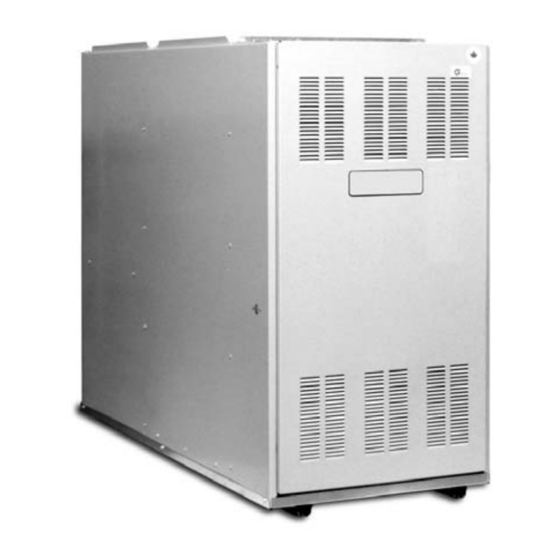
OIL-FIRED WARM AIR
FURNACE
P-LBX16F14501 P-LBX20F19001
(Lowboy Models)
Read this manual completely before beginning
installation.
Important: These instructions must be kept with
the furnace for future reference.
Advertisement
Table of Contents
Troubleshooting

Related Manuals for Coleman P-LBX16F14501


Summary of Contents for Coleman P-LBX16F14501
-
Page 1: Table Of Contents
OIL-FIRED WARM AIR INSTALLATION FURNACE INSTRUCTIONS P-LBX16F14501 P-LBX20F19001 (Lowboy Models) CONTENTS INTRODUCTION............. 2 HEAT LOSS............2 LOCATION OF UNIT ..........2 AIR CONDITIONING..........3 COMBUSTION AIR..........3 CHIMNEY VENTING..........3 OIL TANK ............... 6 PIPING INSTALLATION......... 6 ELECTRICAL CONNECTIONS......6 CIRCULATING AIR BLOWER ....... -
Page 2: Introduction
The P*LBX20F19001 is shipped in two pieces, a furnace section and a blower section, and must be assembled at the IMPROPER INSTALLATION GASOLINE, installation site. Some field wiring is CREATE A CONDITION WHERE THE CRANKCASE OIL, OR ANY OTHER required. P*LBX20F19001 OIL CONTAINING GASOLINE AS A OPERATION... -
Page 3: Air Conditioning
AIR CONDITIONING CHIMNEY VENTING Table 1: Clearance to If the furnace is used in conjunction with The chimney must be sized correctly and Combustibles air conditioning, the furnace shall be be in good repair. If the chimney is installed in parallel with or upstream from oversized, there is a high risk of the flue Furnace P*LBX... - Page 4 The flue pipe should be as short as See Figure 2 and Table 2 for common DRAFT REGULATOR CONTROL possible with horizontal pipes sloping chimney problems and their remedies. This device is used in conjunction with upward toward the chimney at a rate of conventional chimney venting.
- Page 5 Fig. 2: Common Chimney Problems Can be found Obstruction in Use weight to by light and chimney mirror reflecting break and conditions in dislodge. chimney. Must be Lowering a light handled by Joist protruding on an extension competent into chimney. cord.
-
Page 6: Oil Tank
Table 3: Minimum Chimney Base If located indoors, the tank should Table 4: Oil Lines Temperatures (°F) normally be in the lowest level, (cellar, Copper Tubing Oil Line Length (Feet) basement, etc.). It must be equipped Chimney Height (ft.) with a shut-off valve at the tank outlet Single-Pipe Two-Pipe Nozzle... -
Page 7: Circulating Air Blower
accordance with National Fire Normal heat anticipator setting for the MOVED TO ADJUST THE BLOWER Protection Association NFPA-70, P*LBX models is 0.1 A. For more precise SPEED. National Electrical Code, and with local adjustment, the heat anticipator may be codes and regulations. In Canada, all adjusted to the amperage draw of the field wiring should conform to CAN/CSA heating control circuit as measured... -
Page 8: Oil Burner
OIL BURNER adjusted to a gap of 5/32”, 1/16” ahead nozzle is tightened into place, and that of the nozzle, 5/16” above the centerline burner electrodes properly P*LBX furnaces are equipped with of the nozzle. The “Z” dimension (front positioned. Beckett AF Series oil burners with the edge of the burner head to the front face The Beckett burner bulk air band should... -
Page 9: Furnace Installation Set-Up
adjustment plate has been secured, re- reached steady state conditions. This is out on metal furnace parts. If the high check the breech draft and take another the point at which the supply air limit test is successful, shut off the smoke test to ensure that the values temperature stops increasing relative to electrical power to the furnace, restore... -
Page 10: Operating Instructions
fail to maintain indoor temperature during Most circulating motors To Light Unit cold weather, increase fuel consumption permanently lubricated by the motor thermostat above room and cause component failure. manufacturer. These motors will have no temperature to call for heat. The burner oil ports. -
Page 11: Table A-1: Beckett Oil Burner Set-Up
TABLE A-1: BECKETT OIL BURNER SET-UP BECKETT AF SERIES OIL BURNERS FURNACE OUTPUT BURNER NOZZLE PUMP FLOW STATIC HEAD MODEL BTU/Hr. MODEL (Delavan) PRESSURE RATE PLATE 130,000 AF65YB 1.10 / 70°A 100 PSIG 1.10 GPH 2-3/4 in. P*LBX16F14501 143,000 AF65YB 1.20 / 60°A 100 PSIG 1.20 GPH... -
Page 12: Table A-4: Direct Drive Blower Characteristics
TABLE A-4: DIRECT DRIVE BLOWER CHARACTERISTICS TEMP. FURNACE MOTOR MOTOR RISE BLOWER SPEED External Static Pressure – inches W.C. MODEL (∆T) 0.02 0.03 0.04 0.05 0.06 High 1810 1740 1675 1585 1510 Med-High 1570 1540 1495 1445 1375 P*LBX16F14501 70° - 90°F Med-Low 1090 1080... -
Page 13: Wiring Diagram: Model P*Lbx16F14501
WIRING DIAGRAM: MODEL P*LBX16F14501 WIRING DIAGRAM: MODEL P*LBX20F19001... -
Page 14: R7184 Troubleshooting
R7184 TROUBLESHOOTING R7184 Detailed Sequence of Operation (See Figure 7) Power is applied to unit. The R7184 completes a self-diagnostic procedure. If no light or flame is present, and unit passes its self-diagnostic procedure, the control enters into the idle mode. Thermostat calls for heat: A) Safety check is made for flame (4 second delay). -
Page 15: Sequence Of Operation
Fig. 7: R7184 Detailed Sequence of Operation IDLE STATE R7184 THERMOSTAT CALLS FOR HEAT SEQUENCE of OPERATION SAFETY CHECK FOR FLAME (5 SEC.) NO FLAME FLAME REMAINS IN IDLE STATE BURNER MOTOR & IGNITOR START 15 SEC. SOLENOID VALVE OPENS LOCKOUT STATE TRIAL FOR IGNITION R7184:... -
Page 16: R7184 Led Diagnostic Light
R7184 LED Diagnostic Light TROUBLESHOOTING CHECK OIL PRIMARY CONTROL AND IGNITER The LED diagnostic light has several IMPORTANT: potential functions. It indicates the state or mode hazard of line voltage, only a trained, If the trouble does not appear to be in in which the oil burner is operating. - Page 17 TABLE C-2: R7184 TROUBLESHOOTING Condition: Burner motor does not start when there is a call for heat. Procedure Status Corrective Action Check that limit switches are closed and contacts are clean. This includes the burner motor reset button. Check for line voltage power at the oil primary control.
- Page 18 Table C-2: R7184 Troubleshooting continued from previous page Procedure Status Corrective Action Indicator light turns off. Eliminate external light source or permanently shield cad cell. Replace cad cell with new cad cell and recheck. If indicator light does not turn off, remove cad cell lead Shield cell from...
-
Page 19: Table C-3: System And General Troubleshooting
Table C-2: R7184 Troubleshooting continued from previous page Procedure Status Corrective Action 10. Check cad cell. Indicator light is on. Remount control onto burner housing. Go to step 6. • Disconnect line voltage power and open line switch. • Remove existing cad cell and replace with new cad cell. - Page 20 Table C-3: System and General Troubleshooting continued Problem Possible Cause Remedy Photo Cell wiring shorted or Check photo cell (cad cell) wiring for short circuits. Also, check for room light leaking into photo room light leaking into cad cell compartment. Repair light leak if cell compartment necessary.
- Page 21 Table C-3: System and General Troubleshooting continued Problem Possible Cause Remedy System temperature rise ideally should not exceed 85°F. Check System temperature rise too for clogged air filters. Check blower fan for excess dirt build-up or high. debris. Speed up blower fan if necessary. Check “fan off”...
- Page 22 Table C-3: System and General Troubleshooting continued Problem Possible Cause Remedy Airflow blocked or dirty air Clean or replace air filter. filter. Supply air temperature Check all dampers. Open closed dampers including registers in too hot. Insufficient airflow. unused rooms. Check system temperature rise. If temperature rise is too high, speed up blower fan.
-
Page 23: P*Lbx20F19001 Assembly Notes
P*LBX20F19001 ASSEMBLY NOTES Begin fastening the flue pipe flanges together from inside the blower section to the furnace section with the The P*LBX20F19001 oil-fired furnace is shipped in two six 1/4-20 x 3/4 inch screws saved from the removal of pieces;... - Page 24 REPAIR PART LIST – P2LBX16F14501A ITEM DESCRIPTION ITEM DESCRIPTION Panel, Side (Left) Centre, Fan Panel, Side (Right) Relay, Replacement (Centre Fan) Panel, Rear (Upper) Control, Fan and LImit (5”, 200 Deg.) Panel, Blower Division Fuse ABC 15 Amp Slow Blow Panel Assembly, Base Fuse Holder Panel, Inner Front...
- Page 25 REPAIR PART LIST – P4LB SERIES ITEM DESCRIPTION ITEM DESCRIPTION Panel, Left Side (Heating Compartment) Pump, Oil Panel, Right Side (Heating Compartment) 23C Ignitor, Solid State Panel, Left Side (Blower Compartment) 23D Control, Primary Combustion Panel, Right Side (Blower Compartment) Air Tube Combination Panel, Upper Rear (Blower Compartment) Retention Head, Flame (F16)
- Page 26 REPLACEMENT PART CONTACT INFORMATION This is a generic parts list. To request a complete parts list, refer to the contact information below: • Call Consumer Relations at 1-877-874-7378. Follow the instructions to contact the department and/or representative that can assist you. •...
- Page 27 NOTES...
- Page 28 NOTES Subject to change without notice. Printed in U.S.A. 280200-UIM-A-1206 Copyright © by Unitary Products Group. 2006. All rights reserved. Supersedes 035-14289-001 Rev. B (0605) Unitary 5005 Norman Products York Group Drive 73069...