
Related Manuals for Motorola SL1M


Summary of Contents for Motorola SL1M
- Page 1 Final Draft SL1M Portable Radio tTitle Page Basic Service Manual tttt MN000916A01-AA...
- Page 2 Final Draft...
-
Page 3: Computer Software Copyrights
No duplication or distribution of this document or any portion thereof shall take place without the express written permission of Motorola. No part of this manual may be reproduced, distributed, or transmitted in any form or by any means, electronic or mechanical, for any purpose without the express written permission of Motorola. - Page 4 Final Draft Notes...
- Page 5 Final Draft Document History The following major changes have been implemented in this manual since the previous edition: Edition Description Date MN000916A01-AA Initial Release Sept. 2014...
- Page 6 Final Draft Notes...
- Page 7 Trademarks ..............................iii Document History ..................v Commercial Warranty ................xvii Limited Warranty ............................. xvii MOTOROLA COMMUNICATION PRODUCTS ................xvii I. What This Warranty Covers And For How Long ..............xvii II. General Provisions ......................xvii III. State Law Rights ......................xviii IV.
- Page 8 Final Draft viii Table of Contents Chapter 3 Transceiver Performance Testing ........3-1 General ............................3-1 Setup............................3-1 Test Mode ............................ 3-2 3.3.1 Power Up Test Mode ....................... 3-2 3.3.1.1 Display Model ....................3-2 3.3.2 Front Panel AccessTest Mode..................3-2 3.3.2.1 Display Model ....................
- Page 9 Appendix A EMEA Regional Warranty, Service and Technical Support ....................A-1 Warranty and Service Support.....................A-1 A.1.1 Warranty Period and Return Instructions ................A-1 A.1.2 After Warranty Period ......................A-1 European Radio Support Centre (ERSC) ..................A-2 Piece Parts ..........................A-2 Technical Support ........................A-3 Further Assistance From Motorola ....................A-3 Glossary ..................Glossary-1...
- Page 10 Final Draft Table of Contents Notes...
- Page 11 Final Draft List of Figures List of Figures Figure 1-1. Display Model ........................1-2 Figure 1-2. Portable Radio Model Numbering Scheme................1-3 Figure 2-1. Portable Programming Cable with TTR (PMKN4128_)............2-3 Figure 2-2. Micro USB Programming Cable (CB000262A01) ..............2-4 Figure 2-3.
- Page 12 Final Draft List of Figures Notes...
- Page 13 Final Draft List of Tables xiii List of Tables Table 1-1. Radio Frequency Ranges and Power Levels............... 1-1 Table 2-1. Recommended Test Equipment ................... 2-1 Table 2-2. Service Aids ......................... 2-2 Table 2-3. Pin Configuration of Portable Programming Cable with TTR..........2-3 Table 2-4.
- Page 14 Final Draft List of Tables Notes...
- Page 15 Product Safety and RF Exposure ....................6804110J47 Multi-Unit Charger User Guide ....................6866552D01 Quick Reference Guide/Product Safety and RF Exposure............68009553001 MOTOTRBO SL1M Portable User Guide ................MN000892A01 MOTOTRBO SL1M Portable Quick Reference Guide ............. MN000899A01 MOTOTRBO SL1M CMM Leaflet .................... MN000898A01...
- Page 16 Final Draft List of Tables Notes...
-
Page 17: Commercial Warranty
Product Accessories (Including Batteries and Chargers) 12 Months Motorola, at its option, will at no charge either repair the Product (with new or reconditioned parts), replace it (with a new or reconditioned Product), or refund the purchase price of the Product during the warranty period provided it is returned in accordance with the terms of this warranty. - Page 18 Warranty service will be provided by Motorola through one of its authorized warranty service locations. If you first contact the company which sold you the Product, it can facilitate your obtaining warranty service.
- Page 19 A. that MOTOROLA will be notified promptly in writing by such purchaser of any notice of such claim; B. that MOTOROLA will have sole control of the defense of such suit and all negotiations for its settlement or compromise; and C.
- Page 20 Final Draft Battery and Charger Warranty Battery and Charger Warranty Workmanship Warranty The workmanship warranty guarantees against defects in workmanship under normal use and service. Battery Lilon 2200mAh 12 Months Chargers 12 Months Capacity Warranty The capacity warranty guarantees 80% of the rated capacity for the warranty duration. Battery Lilon 2200mAh 12 Months...
-
Page 21: Chapter 1 Introduction
WARNING indicates a potentially hazardous situation which, if not avoided, could result in death or injury. Radio Description The SL1M portable radios are available in the following frequency ranges and power levels. Table 1-1. Radio Frequency Ranges and Power Levels Frequency Band... -
Page 22: Radio Overview
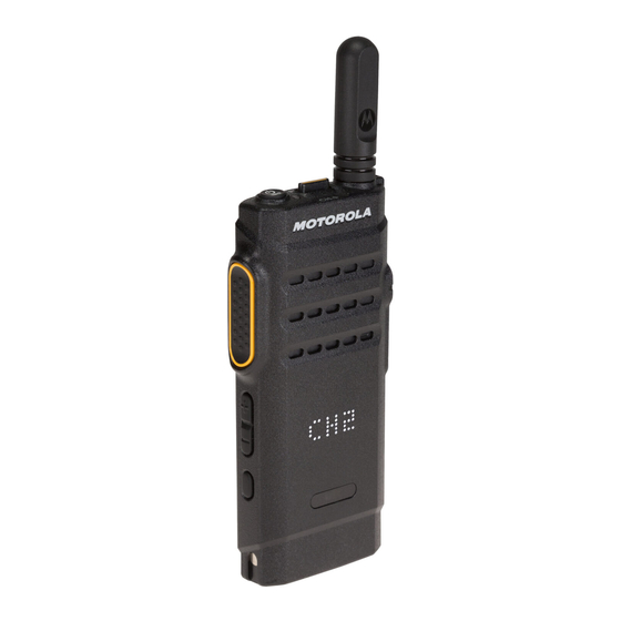
Final Draft Introduction: Radio Description 1.2.1 Radio Overview Antenna LED Indicator Channel Selector Switch On/Off/Information Button Push-to-Talk (PTT) Button Accessory Connector Speaker Microphone Micro USB Connector Volume Up Button Volume Down Button Side Programmable Button Charging Contact Figure 1-1. Display Model •... -
Page 23: Portable Radio Model Numbering Scheme
Final Draft Introduction: Portable Radio Model Numbering Scheme Portable Radio Model Numbering Scheme Model No.Example : Position AZ: APAC Australia LA: Latin America Unique Variation AA: North America N: Standard Package MD: EMEA H: Portable Version Letter 88: SL Series Feature Level Band 2: Non-FM... -
Page 24: Model Charts
Final Draft Introduction: Model Charts Model Charts 1.4.1 VHF (136–174 MHz) 2–3W Model Chart SL1M, VHF 136–174 MHz Model Description AZH88JCP9JA2_N 136–174 MHz, 2–3W, LED Matrix Display, Non Keypad Item Description PMLD4699_ Back Housing Kit Assembly PMLD4697_ Display Front Kit Assembly... -
Page 25: Uhf (403–470 Mhz) 2–3W Model Chart
Final Draft Introduction: Model Charts 1.4.2 UHF (403–470 MHz) 2–3W Model Chart SL1M, UHF 403–470 MHz Model Description AZH88QCP9JA2_N 403–438 MHz, 2–3W, LED Matrix Display, Non Keypad AZH88QCP9JA2_N 403–470 MHz, 2–3W, LED Matrix Display, Non Keypad Item Description PMLE5029_ Back Housing Kit Assembly... -
Page 26: Specifications
Final Draft Introduction: Specifications Specifications General SL1M Display Channel Capacity Frequency VHF : 136–174 MHz UHF: 403–470 MHz Dimensions (HxWxT) 125.7 x 55.0 x 22.0 mm with Lilon battery Weight 163.4g with Lilon battery Power Supply 3.7 V nominal FCC Description... - Page 27 Final Draft Introduction: Specifications Receiver SL1M Frequencies VHF: 136–174 MHz UHF: 403–470 MHz Channel Spacing 12.5 kHz/25kHz Frequency Stability (-30°C to +60°C, +/-1.5 ppm +25°C Ref) Analog Sensitivity (12 dB SINAD) 0.3 µV 0.22 µV (typical) Digital Sensitivity (5% BER) 0.25 µV...
- Page 28 Final Draft Introduction: Specifications Transmitter SL1M Frequencies VHF: 136–174 MHz UHF: 403–470 MHz Channel Spacing 12.5 kHz/25 kHz Frequency Stability (-30°C to +60°C) +/-1.5 ppm Power Output (Low Power) Power Output (High Power) Analog: 2W Digital: 3W Modulation Limiting +/-2.5 kHz @ 12.5 kHz +/-5.0 kHz @ 25 kHz...
- Page 29 Final Draft Introduction: Specifications UHF Self-Quieter Frequencies 403.20 MHz ± 15 kHz 408.00 MHz ± 10 kHz 412.80 MHz ± 10 kHz 417.60 MHz ± 10 kHz 422.40 MHz ± 15 kHz 427.20 MHz ± 10 kHz 432.00 MHz ± 20 kHz 436.80 MHz ±...
- Page 30 Final Draft 1-10 Introduction: Specifications Applicable 810C 810D 810E 810F 810G MIL-STD Methods Procedures Methods Procedures Methods Procedures Methods Procedures Methods Procedures 500.1 500.2 500.3 500.4 I/II 500.5 I/II Pressure High 501.1 I,II 501.2 I/AI,II/AI 501.3 I/A1, II/A1 501.4 I/HOT, II/ 501.5 I/A1, II/A2 Temperature...
-
Page 31: Chapter 2 Test Equipment And Service Aids
Final Draft Chapter 2 Test Equipment and Service Aids Recommended Test Equipment The list of equipment contained in Table includes most of the standard test equipment required for servicing Motorola portable radios. Table 2-1. Recommended Test Equipment Equipment Characteristics Example... -
Page 32: Service Aids
Table 2-2 lists the service aids recommended for working on the radio. While all of these items are available from Motorola, most are standard workshop equipment items, and any equivalent item capable of the same performance may be substituted for the item listed. -
Page 33: Portable Programming Cable
Final Draft Test Equipment and Service Aids: Portable Programming Cable Portable Programming Cable Figure 2-1. Portable Programming Cable with TTR (PMKN4128_) Table 2-3. Pin Configuration of Portable Programming Cable with TTR CONNECTION Function VCC(5V) DATA- DATA+ BNC Center Pin BNC Shell GROUND... -
Page 34: Micro Usb Programming Cable
Final Draft Test Equipment and Service Aids: Micro USB Programming Cable Micro USB Programming Cable Figure 2-2. Micro USB Programming Cable (CB000262A01) Table 2-4. Pin Configuration of Micro USB Programming Cable CONNECTION CONN 1 CONN 2 Function VBUS DATA- DATA+ GROUND... -
Page 35: Audio Test Cable
Final Draft Test Equipment and Service Aids: Audio Test Cable Audio Test Cable Figure 2-3. Audio Test Cable (CB000233A01) Table 2-5. Pin Configuration of Audio Test Cable CONNECTION Function SPK+ MIC+ 2,7,16 MIC-,SPK-... - Page 36 Final Draft Test Equipment and Service Aids: Audio Test Cable Notes...
-
Page 37: Chapter 3 Transceiver Performance Testing
Do NOT use any form of connector, e.g. wires, crocodile clips, and probes, to supply voltage to the radio, other than the Motorola approved battery eliminator. The initial equipment control settings is shown in Table 3-1. The remaining tables in this chapter... -
Page 38: Test Mode
Final Draft Transceiver Performance Testing: Test Mode Table 3-1. Initial Equipment Control Settings Service Monitor Power Supply Test Set Oscilloscope Source: Mod Current: 2.5 A Oscilloscope Horizontal: 10mSec/Div Oscilloscope Vertical: 2.5kHz/Div Oscilloscope Trigger: Auto Monitor Image: Hi Monitor Bandwidth: Narrow Monitor Squelch: Middle setting Monitor Vol: 1/4 setting Test Mode... - Page 39 Final Draft Transceiver Performance Testing Test Mode 12.5 kHz (First character) (Fourth character) (Second and third character) Figure 3-2. Channel Profile Screen Icon 3. A short press of the Side Programmable Button changes the Test Environment from CSQ –> TPL –> DIG –> USQ –> CSQ. - The radio beeps once for CSQ mode - The radio beeps twice for TPL mode - The radio beeps three times for DIG mode...
- Page 40 Final Draft Transceiver Performance Testing: Test Mode Table 3-3. Test Frequencies Channel Selector Test UHF RX UHF TX VHF RX VHF TX Switch Channel Position 1 Low Power TX#1 or #9 403.150 403.150 136.075 136.075 9 High Power RX#1 or #9 2 Low Power TX#2 or #10 414.150...
- Page 41 Final Draft Transceiver Performance Testing Test Mode Table 3-4. Transmitter Performance Checks Test Communications Radio Test Set Comments Name Analyzer Reference Mode: PWR MON TEST MODE, PTT to Frequency error to be Frequency 4th channel test Test Channel 4 continuously ±201Hz for UHF frequency* carrier squelch...
- Page 42 Final Draft Transceiver Performance Testing: Test Mode Test Communications Radio Test Set Comments Name Analyzer Magnitude DMR Mode. Magnitude As above As above Not Exceed 1% Error error Symbol DMR Mode. Symbol As above As above Symbol Deviation Deviation Deviation should be within 648Hz +/- 10% and 1944Hz +/- 10%...
- Page 43 Final Draft Transceiver Performance Testing Test Mode Table 3-5. Receiver Performance Checks Communications Test Name Radio Test Set Comments Analyzer Reference Mode: PWR MON TEST MODE, PTT to Frequency error to be Frequency 4th channel test Test Channel continuously ±201Hz for UHF frequency* 4 carrier transmit (during the...
-
Page 44: Led Status Test Mode
Final Draft Transceiver Performance Testing: Test Mode 3.3.4 LED Status Test Mode 3.3.4.1 Display Model 1. Press and hold the Side Programmable Button, to switch from RF Test Model to LED Status Test Mode. 2. The radio beeps once, and display shows LED. 3. -
Page 45: Battery Check Test Mode
Final Draft Transceiver Performance Testing Test Mode 3. The radio shall route any audio on the external mic to the earpiece. 4. The radio display shows LOOP. 3.3.9 Battery Check Test Mode 3.3.9.1 Display Model 1. Press and hold the Side Programmable Button, to switch from Audio Loopback Earpiece Test Mode to Battery Check Test Mode. - Page 46 Final Draft 3-10 Transceiver Performance Testing Test Mode Notes...
-
Page 47: Chapter 4 Radio Programming And Tuning
Final Draft Chapter 4 Radio Programming and Tuning Introduction This chapter provides an overview of the MOTOTRBO Customer Programming Software (CPS), as well as the Tuner and AirTracer applications, which are all designed for use in Windows 7 and Windows 8 environment. These programs are available in one kit as listed in Table 4-1. An Installation Guide is also included with the kit. - Page 48 Final Draft Radio Programming and Tuning: Customer Programming Software Setup RF antenna adaptor holder RF antenna (HW000406A01) adaptor (28012039001) Figure 4-2. Connecting RF Antenna Adaptor To Radio RF Input/Output Port RF plug (EN000047A01) Figure 4-3. RF Plug...
-
Page 49: Airtracer Application Tool
The AirTracer application tool can also retrieve and save internal error logs from MOTOTRBO radios. The saved files can be analyzed by trained Motorola personnel to suggest improvements in system configurations or to help isolate problems. - Page 50 Final Draft Radio Programming and Tuning: Radio Tuning Setup Notes...
-
Page 51: Chapter 5 Disassembly And Reassembly Procedures
• Safe handling of CMOS and LDMOS devices. • Repair procedures and techniques. • Disassembly and re-assembly of the radio. Only Motorola Service Centers or Authorized Motorola Service Dealers can perform this function. C a u t i o n Preventive Maintenance Periodic visual inspection and cleaning is recommended. -
Page 52: Inspection
Final Draft Disassembly And Reassembly Procedures: Preventive Maintenance 5.2.1 Inspection Check that the external surfaces of the radio are clean, and that all external controls and switches are functional. It is not recommended to inspect the interior electronic circuitry. 5.2.2 Cleaning Procedures The following procedures describe the recommended cleaning agents and the methods to be used when cleaning the external and internal surfaces of the radio. -
Page 53: Safe Handling Of Cmos And Ldmos Devices
• Ground the working surface of the service bench to protect the CMOS/LDMOS device. We recommend using the Motorola Static Protection Assembly (part number 0180386A82), which includes a wrist strap, two ground cords, a table mat, and a floor mat. -
Page 54: Repair Procedures And Techniques – General
When damaged parts are replaced, identical parts should be used. If the identical replacement part is not locally available, check the parts list for the proper Motorola part number and order the part from the nearest Motorola Radio Products and Solutions Organization (RPSO) listed in Appendix A of this manual. -
Page 55: Disassembling And Reassembling The Radio – General
If a unit requires further testing or service than is customarily performed at the basic level, please send the radio to a Motorola Service Center Appendix A. To assure the safety and regulatory compliance of the SL1M, the radio must be repaired only at Motorola service facilities. Please contact your local dealer or Point of sale for futher instructions. -
Page 56: Radio Disassembly – Detailed
Final Draft Disassembly And Reassembly Procedures: Radio Disassembly – Detailed Radio Disassembly – Detailed 5.6.1 Holster Disassembly 1. Remove the holster from radio as shown in Figure 5-1. Figure 5-1. Holster Removal 5.6.2 External Antenna Disassembly 1. Turn off the radio. 2. -
Page 57: Back Housing Disassembly
Final Draft Disassembly And Reassembly Procedures: Radio Disassembly – Detailed 5.6.3 Back Housing Disassembly 1. Remove the 2 screw plugs from the back housing as shown in Figure 5-3. NOTE:Remove the screw plug with plastic tweezer. Figure 5-3. Screw Plug Removal 2. - Page 58 Final Draft Disassembly And Reassembly Procedures: Radio Disassembly – Detailed NOTE:Remove the RF plug with plastic tweezer. 3. Unlock the battery door by sliding the latch to the right as shown in Figure 5-5. Figure 5-5. Unlock The Battery Door 4.
- Page 59 Final Draft Disassembly And Reassembly Procedures: Radio Disassembly – Detailed 5. Once the battery door is removed, remove the battery from its battery compartment as shown in Figure 5-7. To remove the battery, grasp the battery grove as the bottom of the battery and lift it up.
- Page 60 Final Draft 5-10 Disassembly And Reassembly Procedures: Radio Disassembly – Detailed 7. Lift the back housing from the front housing, using the Opener Back Housing as shown in Figure 5-10. Figure 5-9. Back Housing Removal Figure 5-10. Back Housing Removal...
-
Page 61: Main Pcb Disassembly
Final Draft Disassembly And Reassembly Procedures: Radio Disassembly – Detailed 5-11 5.6.4 Main PCB Disassembly 1. Detach the Top Control Flex, PTT Flex, and Display Flex from the main PCB, using plastic tweezers in the direction indicated in Figure 5-11. 2. - Page 62 Final Draft 5-12 Disassembly And Reassembly Procedures: Radio Disassembly – Detailed 3. Detach the Audio Jack, Speaker, Micro USB, Microphone Flex and Display Flex from the main PCB, using plastic tweezers in the direction indicated in Figure 5-13. Audio Jack, Speaker, Micro USB and Microphone Flex Display Flex Disassembly...
-
Page 63: Audio Jack Flex, Micro Usb Flex, Microphone (Mic), Speaker Flex, Lcd Display, And Internal Antenna Disassembly
Final Draft Disassembly And Reassembly Procedures: Radio Disassembly – Detailed 5-13 5.6.5 Audio Jack Flex, Micro USB Flex, Microphone (MIC), Speaker Flex, LCD Display, and Internal Antenna Disassembly 1. Remove the internal frame screws by using T06 Torx Plus screwdriver as shown in Figure 5-14. - Page 64 Final Draft 5-14 Disassembly And Reassembly Procedures: Radio Disassembly – Detailed 3. Firstly remove the micro USB carefully, followed by the microphone, the audio jack, and the speaker as shown in Figure 5-16. Audio Jack Microphone Speaker Micro USB Figure 5-16. Speaker Disassembly 4.
-
Page 65: Dust Cover Disassembly
Final Draft Disassembly And Reassembly Procedures: Radio Disassembly – Detailed 5-15 5. Remove the internal antenna by lifting upwards as shown in Figure 5-18. Figure 5-18. Internal Antenna Disassembly 5.6.6 Dust Cover Disassembly 1. Cut off the dust cover head. Dust Cover Head Figure 5-19. -
Page 66: Radio Reassembly – Detailed
Final Draft 5-16 Disassembly And Reassembly Procedures: Radio Reassembly – Detailed 2. Pull the dust cover out from the front housing as shown in Figure 5-20. Figure 5-20. Dust Cover Removal Radio Reassembly – Detailed 5.7.1 Dust Cover Reassembly 1. Insert the dust cover tail into the front housing middle hole openings as shown in Figure 5-21. Figure 5-21. -
Page 67: Internal Antenna Reassembly
Final Draft Disassembly And Reassembly Procedures: Radio Reassembly – Detailed 5-17 2. Use a long nose plier and pull the tail inward, from inner part of the housing until the head is fully inserted as shown in Figure 5-22. Dust cover tail Figure 5-22. -
Page 68: Lcd Display Reassembly
Final Draft 5-18 Disassembly And Reassembly Procedures: Radio Reassembly – Detailed 5.7.3 LCD Display Reassembly 1. Insert the display module into front housing as shown in Figure 5-24. Figure 5-24. Display Module Reassembly 5.7.4 Audio Jack Flex, Micro USB Flex, Microphone (MIC), Speaker Flex, LCD Display, and Internal Antenna Reassembly 1. -
Page 69: Internal Frame Reassembly
Final Draft Disassembly And Reassembly Procedures: Radio Reassembly – Detailed 5-19 5.7.5 Internal Frame Reassembly 1. Insert the internal frame into the front housing, with a little slanting to ensure the internal frame is properly sits on the front housing ribs as shown in Figure 5-26. Housing Rib Internal Frame Figure 5-26. -
Page 70: Main Pcb Reassembly
Final Draft 5-20 Disassembly And Reassembly Procedures: Radio Reassembly – Detailed 5.7.6 Main PCB Reassembly 1. Attach the Audio Jack, Speaker, Micro USB, and Microphone Flex to the connector located at the bottom side of the main PCB as shown in Figure 5-28. 2. -
Page 71: Back Housing Reassembly
Final Draft Disassembly And Reassembly Procedures: Radio Reassembly – Detailed 5-21 Top Control Flex PTT Flex Display Flex Figure 5-29. Main PCB Reassembly 5.7.7 Back Housing Reassembly 1. Place the back housing onto the front housing as shown in Figure 5-30, and press the back housing towards the front housing. - Page 72 Final Draft 5-22 Disassembly And Reassembly Procedures: Radio Reassembly – Detailed 2. Screw in all 6 screws to the back housing using T06 Torx Plus screwdriver as shown in Figure 5-31. Do not over torque the screws. Please refer to Table 5-4 for screws torque specifications.
- Page 73 Final Draft Disassembly And Reassembly Procedures: Radio Reassembly – Detailed 5-23 4. Attach and lock battery door by sliding the latch to the left as shown in Figure 5-33. Figure 5-33. Lock The Battery Door 5. Insert one RF plug, and two new screw plugs at the back housing as shown in Figure 5-34. Figure 5-34.
-
Page 74: External Antenna Reassembly
Final Draft 5-24 Disassembly And Reassembly Procedures: Radio Reassembly – Detailed 5.7.8 External Antenna Reassembly 1. Turn the antenna clockwise to engage the antenna to the front housing. Figure 5-35. External Antenna Reassembly 5.7.9 Holster Reassembly 1. Attach the holster to radio as shown in Figure 5-36. Figure 5-36. -
Page 75: Radio Exploded Mechanical Views And Parts Lists
Final Draft Disassembly And Reassembly Procedures: Radio Exploded Mechanical Views and Parts Lists 5-25 Radio Exploded Mechanical Views and Parts Lists 10.0 11.0 12.0 Figure 5-37. SL1MExploded View... - Page 76 Screw, Back Housing FN000069A01 RF Plug EN000047A01 Screw Plug EN000037A01 10.0 Battery Door Kit Assembly PMLN7074_ 11.0 Battery See Accessory Table 12.0* Display Flex, Assembly 0104063J29 Note: * Item for Display Model only Table 5-3. SL1M Exploded View Parts List...
-
Page 77: Torque Chart
Final Draft Disassembly And Reassembly Procedures: Torque Chart 5-27 Torque Chart Table 5-4 lists the various screws by part number and description, followed by the torque values in different units of measure. Torque all screws to the recommended value when assembling the radio. A proper torque screwdriver must be used during installation to ensure that these torque values are not exceeded. - Page 78 Final Draft 5-28 Disassembly And Reassembly Procedures: Torque Chart Notes...
-
Page 79: Chapter 6 Basic Troubleshooting
Chapter 3 or exhibits an error code listed below, then the circuit board should be replaced. If repair requires knowledge of details of component level troubleshooting, please send radio to a Motorola Service Center or listed in Motorola Authorised Dealers . NOTE To access the various connector pins, use the housing eliminator/test fixture along with the diagrams found in this section of the manual. - Page 80 Radio RAM Test Failure. Fatal Retest radio by turning it off and turning it on again. If message reoccurs, replace main board or send radio to nearest Motorola Depot. FAIL 01/90 General hardware test failure. Fatal Retest radio by turning it off and turning it on again.
-
Page 81: Operational Error Codes
Problems detected during these tests are presented as error codes on the radio’s display. The presence of an error code should prompt a user that a problem exists and that a Motorola Authorized MOTOTRBO dealer should be contacted. Use Table 6-2 to aid in understanding any particular operational error codes. - Page 82 Final Draft Basic Troubleshooting: Operational Error Codes Notes...
- Page 83 Chapter 7 Accessories Introduction Motorola provides the following approved accessories to improve the productivity of your digital portable two-way radio. For a list of Motorola-approved antennas, batteries and other accessories, visit the following web site: http://www.motorolasolutions.com/mototrbo/slseries 7.1.1 Antennas Part No.
- Page 84 Final Draft Accessories: Introduction 7.1.5 Charges Part No. Description PMLN7093_ Standard Multi-Unit Charger PMLN7094_ Standard Single Unit Charger PMLN7100_ Standard Multi-Unit Charger, China Plug PMLN7103_ Standard Multi-Unit Charger, AUS/NZ Plug PMLN7105_ Standard Multi-Unit Charger, Korea Plug PMLN7107_ Standard Multi-Unit Charger, Japan Plug PMLN7108_ Standard Single Unit Charger, China Plug PMLN7111_...
- Page 85 Level 3 Maintenance The Level 3 Maintenance can only be done at the Motorola Service Center/Depot since it can deeply affect the performance of the radio. To find out more about Motorola Service Center, please visit http://www.motorolasolutions.com...
- Page 86 Additional Service Kits Information A.3.1 UHF Super Tanapa SL1M, UHF 403–470 MHz 2–3 W Model Description AZH88QCP9JA2AN 403–470 MHz, 2–3 W, SL1M Display Model Item Description PMUE4541AAMAAA SL1M 403–470M 2–3 W Display Model PMUE4541AAMACA SL1M 403–438M 2–3 W Display Model X = Item Included A.3.2 VHF Super Tanapa...
-
Page 87: Glossary
Final Draft Glossary Glossary This glossary contains an alphabetical listing of terms and their definitions that are applicable to portable and mobile subscriber radio products. All terms do not necessarily apply to all radios, and some terms are merely generic in nature. Term Definition Band... - Page 88 Final Draft Glossary-2 Term Definition Spectrum Frequency range within which radiation has specific characteristics. Squelch Muting of audio circuits when received signal levels fall below a pre- determined value. With carrier squelch, all channel activity that exceeds the radio’s preset squelch level can be heard. Transceiver Transmitter-receiver.
- Page 89 Final Draft...