Omron NJ501-1300 User Manual
Sysmac machine automation controller, nj-series, cpu unit built-in ethernet/ip port
Hide thumbs
Also See for NJ501-1300:
- User manual (180 pages) ,
- Reference manual (990 pages) ,
- Troubleshooting manual (208 pages)

Related Manuals for Omron NJ501-1300


Summary of Contents for Omron NJ501-1300
- Page 1 Machine Automation Controller NJ-series CPU Unit Built-in EtherNet/IP Port User’s Manual NJ501-1300 NJ501-1400 NJ501-1500 CPU Unit W506-E1-01...
- Page 2 OMRON. No patent liability is assumed with respect to the use of the information contained herein. Moreover, because OMRON is constantly striving to improve its high-quality products, the information contained in this manual is subject to change without notice.
- Page 3 For programming, this manual is intended for personnel who understand the programming language specifications in international standard IEC 61131-3 or Japanese standard JIS B3503. Applicable Products This manual covers the following products. • NJ-series CPU Units • NJ501-1300 • NJ501-1400 • NJ501-1500 NJ-series CPU Unit Built-in EtherNet/IP Port User’s Manual (W506)
- Page 4 Relevant Manuals Relevant Manuals There are three manuals that provide basic information on the NJ-series CPU Units: the NJ-series CPU Unit Hardware User’s Manual, the NJ-series CPU Unit Software User’s Manual (this manual), and the NJ-series Instructions Reference Manual. Most operations are performed from the Sysmac Studio Automation Software. Refer to the Sysmac Stu- dio Version 1 Operation Manual (Cat.
- Page 5 Manual Configuration Manual Configuration NJ-series CPU Unit Hardware User’s Manual (Cat. No. W500) Section Description This section provides an introduction to the NJ-series Controllers and their features, Section 1 and gives the NJ-series Controller specifications. Introduction This section describes the system configuration used for NJ-series Controllers. Section 2 System Configuration This section describes the parts and functions of the configuration devices in the NJ-...
-
Page 6: Message Communications
Manual Configuration NJ-series CPU Unit Built-in EtherNet/IP Port User’s Manual (Cat. No. W506) (This Manual) Section Description This section provides an overview and the specifications of the built-in EtherNet/IP Section 1 port on an NJ-series Controller. It introduces EtherNet/IP communications and Introduction describes the system configuration and operating procedures. - Page 7 Manual Configuration Sysmac Studio Version 1 Operation Manual (Cat. No. W504) Section Description This section provides an overview and lists the specifications of the Sysmac Studio Section 1 and describes its features and components. Introduction This section describes how to install and uninstall the Sysmac Studio. Section 2 Installation and Uninstallation This section describes the basic concepts for designing an NJ-series System with the...
- Page 8 Manual Structure Manual Structure Page Structure The following page structure is used in this manual. Level 1 heading 4 Installation and Wiring Level 2 heading Level 3 heading Level 2 heading Mounting Units Gives the current Level 3 heading headings. 4-3-1 Connecting Controller Components The Units that make up an NJ-series Controller can be connected simply by pressing the Units together...
- Page 9 Manual Structure Precaution on Terminology In this manual, “download” refers to transferring data from the Sysmac Studio to the physical Controller and “upload” refers to transferring data from the physical Controller to the Sysmac Studio. For the Sysmac Studio, synchronization is used to both upload and download data. Here, “synchronize” means to automatically compare the data for the Sysmac Studio on the computer with the data in the physical Controller and transfer the data in the direction that is specified by the user.
- Page 10 Manual Structure NJ-series CPU Unit Built-in EtherNet/IP Port User’s Manual (W506)
- Page 11 Sections in this Manual Sections in this Manual Introduction FTP Server Installing Ethernet Automatic Clock Networks Adjustment System-defined Variables Related to the Built-in SNMP Agent EtherNet/IP Port Communications Per- Determining formance and Commu- IP Addresses nications Load Sysmac Studio Settings for the Built-in Troubleshooting EtherNet/IP Port...
- Page 12 Sections in this Manual NJ-series CPU Unit Built-in EtherNet/IP Port User’s Manual (W506)
- Page 13 CONTENTS CONTENTS Introduction....................... 1 Relevant Manuals...................... 2 Manual Configuration....................3 Manual Structure ...................... 6 Sections in this Manual.................... 9 Read and Understand this Manual ................ 17 Safety Precautions ....................21 Precautions for Safe Use ..................23 Precautions for Correct Use .................. 24 Regulations and Standards ...................
- Page 14 Section 2 Installing Ethernet Networks Selecting the Network Devices....................2-2 2-1-1 Recommended Network Devices....................2-2 2-1-2 Network Devices Manufactured by OMRON ................2-3 2-1-3 Ethernet Switch Types ........................ 2-3 2-1-4 Ethernet Switch Functions ......................2-3 2-1-5 Precautions for Ethernet Switch Selection .................. 2-4 Network Installation.........................
- Page 15 CONTENTS Section 6 Testing Communications Testing Communications ......................6-2 6-1-1 PING Command ......................... 6-2 6-1-2 Using the PING Command ......................6-2 6-1-3 Host Computer Operation......................6-3 Section 7 Tag Data Link Functions Introduction to Tag Data Links ....................7-2 7-1-1 Tag Data Links ..........................
- Page 16 CONTENTS 8-3-4 Ethernet Link Object (Class ID: F6 Hex) ................... 8-34 8-3-5 Controller Object (Class ID: C4 Hex) ..................8-38 Section 9 Socket Service Basic Knowledge on Socket Communications..............9-2 9-1-1 Sockets ............................9-2 9-1-2 Port Numbers for Socket Services ....................9-2 Basic Knowledge on Protocols ....................
- Page 17 CONTENTS Section 11 Automatic Clock Adjustment 11-1 Automatic Clock Adjustment....................11-2 11-1-1 Overview........................... 11-2 11-1-2 Specifications..........................11-3 11-2 Procedure to Use the Automatic Clock Adjustment Function .......... 11-4 11-2-1 Procedure ..........................11-4 11-2-2 Settings Required for Automatic Clock Adjustment ..............11-4 11-2-3 NTP Display..........................
- Page 18 CONTENTS Section 14 Troubleshooting 14-1 Overview of Errors......................... 14-2 14-1-1 How to Check for Errors ......................14-2 14-1-2 Errors Related to the EtherNet/IP Function Module..............14-6 14-2 Troubleshooting........................14-9 14-2-1 Error Table..........................14-9 14-2-2 Error Descriptions ........................14-14 14-2-3 Troubleshooting........................14-37 14-3 Checking Status with the Network Configurator ..............
- Page 19 WHETHER SUCH CLAIM IS BASED ON CONTRACT, WARRANTY, NEGLIGENCE, OR STRICT LIABILITY. In no event shall the responsibility of OMRON for any act exceed the individual price of the product on which liability is asserted. IN NO EVENT SHALL OMRON BE RESPONSIBLE FOR WARRANTY, REPAIR, OR OTHER CLAIMS...
- Page 20 Application Considerations SUITABILITY FOR USE OMRON shall not be responsible for conformity with any standards, codes, or regulations that apply to the combination of products in the customer's application or use of the products. At the customer's request, OMRON will provide applicable third party certification documents identifying ratings and limitations of use that apply to the products.
- Page 21 Performance data given in this manual is provided as a guide for the user in determining suitability and does not constitute a warranty. It may represent the result of OMRON's test conditions, and the users must correlate it to actual application requirements. Actual performance is subject to the OMRON Warranty and Limitations of Liability.
- Page 22 Read and Understand this Manual NJ-series CPU Unit Built-in EtherNet/IP Port User’s Manual (W506)
- Page 23 Safety Precautions Safety Precautions Definition of Precautionary Information The following notation is used in this manual to provide precautions required to ensure safe usage of the built-in EtherNet/IP port on an NJ-series CPU Unit. The safety precautions that are provided are extremely important to safety.
- Page 24 Safety Precautions Symbols The circle and slash symbol indicates operations that you must not do. The specific operation is shown in the circle and explained in text. This example indicates prohibiting disassembly. The triangle symbol indicates precautions (including warnings). The specific operation is shown in the triangle and explained in text. This example indicates a precaution for electric shock.
- Page 25 Precautions for Safe Use Precautions for Safe Use Refer to the following manuals for precautions for the safe use of the built-in EtherNet/IP port. Installation precautions are also provided for the NJ-series CPU Unit and NJ-series Controller system. • NJ-series CPU Unit Hardware User’s Manual (W500) •...
- Page 26 Precautions for Correct Use Precautions for Correct Use Refer to the following manuals for precautions for the correct use of the built-in EtherNet/IP port. Installation precautions are also provided for the NJ-series CPU Unit and NJ-series Controller system. • NJ-series CPU Unit Hardware User’s Manual (W500) •...
- Page 27 Concepts EMC Directive OMRON devices that comply with EC Directives also conform to the related EMC standards so that they can be more easily built into other devices or the overall machine. The actual products have been checked for conformity to EMC standards.* Whether the products conform to the standards in the system used by the customer, however, must be checked by the customer.
- Page 28 The NJ-series Controllers comply with the following shipbuilding standards. Applicability to the ship- building standards is based on certain usage conditions. It may not be possible to use the product in some locations. Contact your OMRON representative before attempting to use a Controller on a ship.
- Page 29 Gives the lot number and serial number of the Unit. serial number DDMYY: Lot number, @: For use by OMRON, xxxx: Serial number “M” gives the month (1 to 9: January to September, X: October, Y: November, Z: December) MAC address Gives the MAC address of the built-in port on the Unit.
- Page 30 Unit Versions Right-click any open space in the Unit Editor and select Production Information. The Production Information Dialog Box is displayed. Simple Display Detailed Display In this example, “Ver.1.0” is displayed next to the unit model. The following items are displayed. CPU Unit CJ-series Units Unit model...
- Page 31 Unit Versions Unit Version Notation In this manual, unit versions are specified as shown in the following table. Product nameplate Notation in this manual Remarks “Ver.1.0” or later to the right of Unit version 1.0 or later Unless unit versions are specified, the information in this manual the lot number applies to all unit versions.
- Page 32 When programming, use this manual together Manual trol instructions that are with the NJ-series CPU Unit Hardware User’s provided by OMRON. Manual (Cat. No. W500), NJ-series CPU Unit Software User’s Manual (Cat. No. W501) and NJ-series CPU Unit Motion Control User’s Man- ual (Cat.
- Page 33 Related Manuals Manual name Cat. No. Model numbers Application Description NJ-series CPU Unit Built- W505 NJ501-@@@@ Using the built-in EtherCAT Information on the built-in EtherCAT port is pro- in EtherCAT Port User’s port on an NJ-series CPU vided. This manual provides an introduction and Manual Unit.
- Page 34 Revision History Revision History A manual revision code appears as a suffix to the catalog number on the front and back covers of the manual. W506-E1-01 Cat. No. Revision code Revision code Date Revised content July 2011 Original production NJ-series CPU Unit Built-in EtherNet/IP Port User’s Manual (W506)
-
Page 35: Socket Service
Introduction 1-1 Introduction ..........1-2 1-1-1 EtherNet/IP Features . -
Page 36: Introduction
1 Introduction Introduction 1-1-1 EtherNet/IP Features EtherNet/IP is an industrial multi-vendor network that uses Ethernet. The EtherNet/IP specifications are open standards managed by the ODVA (Open DeviceNet Vendor Association), just like DeviceNet. Eth- erNet/IP is not just a network between Controllers. It is also used as a field network. Because Ether- Net/IP uses standard Ethernet technology, various general-purpose Ethernet devices can be used in the network. -
Page 37: Features Of Built-In Ethernet/Ip Port On Nj-Series Cpu Units
1 Introduction 1-1-2 Features of Built-in EtherNet/IP Port on NJ-series CPU Units Tag Data Links Cyclic communications between Controllers or between Controllers and other devices are possible on an EtherNet/IP network. Tag data links can quickly perform data exchanges for up to 9,600 words of data. - Page 38 1 Introduction Complete Troubleshooting Functions A variety of functions are provided to quickly identify and handle errors. • Self-diagnosis at startup • Event log that records the time of occurrence and other error details Additional Information CIP (Common Industrial Protocol) CIP is a shared industrial protocol for the OSI application layer.
-
Page 39: System Configuration And Configuration Devices
(1) Per Node These Units are used to connect to an EtherNet/IP net- NJ501-@@@@ NJ-series CPU Unit (built-in Ether- work. Net/IP port) OMRON PLCs CJ2H-CPU@@-EIP or CJ2M-CPU3@ CJ2 CPU Unit (built-in EtherNet/IP port) CJ-series CJ1W-EIP21 EtherNet/IP Unit* CS-series CS1W-EIP21 EtherNet/IP Unit... -
Page 40: Support Software Required To Construct A Network
1 Introduction 1-2-2 Support Software Required to Construct a Network This section describes the Support Software that is required to construct an EtherNet/IP network. The built-in EtherNet/IP port has Ethernet Settings and Tag Data Link Settings, which are stored in the non- volatile memory of the CPU Unit. -
Page 41: Built-In Ethernet/Ip Port
1 Introduction Built-in EtherNet/IP Port 1-3-1 Specifications Item Specifications TCP/IP or UDP/IP Communications protocol Sysmac Studio connection, tag data link, CIP message communications, socket services, FTP Supported services server, automatic clock adjustment (NTP client), SNMP agent, DNS client, and BOOTP client 100Base-TX or 10Base-T (100Base-TX is rec- Physical layer ommended.) - Page 42 1 Introduction Item Specifications Number of connections: 32 (clients + servers) Class 3 (connected) Number of clients that can communicate at one CIP message ser- time: 32 max. vice: Explicit mes- UCMM (unconnected) sages Number of servers that can communicate at one time: 32 max.
-
Page 43: Part Names And Functions
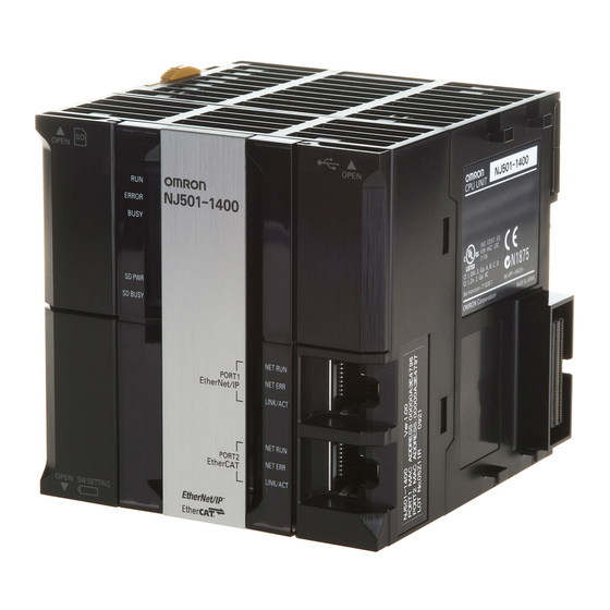
1 Introduction 1-3-2 Part Names and Functions USB port Built-in EtherNet/IP port Built-in EtherCAT port Indicators Ethernet Address Notation A specific Ethernet address is allocated to each device connected to the Ethernet network. The built-in EtherNet/IP port’s address is listed in 12-digit hexadecimal in the two places shown below on the CPU Unit. - Page 44 1 Introduction Indicators (LEDs) NET RUN, NET ERR, and LINK/ACT • NET RUN indicator: This shows the status of the CIP connection (tag data links, Class 3 mes- sages). • NET ERR indicator: This shows the network communications error status. Refer to Section 14 Troubleshooting and Error Processing for details.
-
Page 45: Introduction To Communications Services
1 Introduction Introduction to Communications Services 1-4-1 CIP (Common Industrial Protocol) Communications Services Tag Data Links (Cyclic Communications) A program is not required to perform cyclic data exchanges with other devices on the EtherNet/IP net- work. Normally, a connection is started with the target device for each tag set that was created with the Network Configurator to start communications for tag data links for a built-in EtherNet/IP port. -
Page 46: Bootp Client
1 Introduction Message Communications (Class 3 UCMM: Unconnected Message Service) User-specified CIP commands can be sent to devices on the EtherNet/IP network. CIP commands, such as those for reading and writing data, can be sent and their responses received by executing the CIP Send instruction from the user program in the NJ-series CPU Unit (without a connection). -
Page 47: Ftp Server
1 Introduction 1-4-3 FTP Server An FTP server is built into the built-in EtherNet/IP port so that files can be read from and written to the SD Memory Card in the CPU Unit of the Controller from computers at other Ethernet nodes. This makes it possible to exchange data files between a host computer and the Controller with the host com- puter as the FTP client and the Controller as the FTP server. -
Page 48: Socket Service
1 Introduction 1-4-5 Socket Service You can send data to and receive data from any node on Ethernet with the UDP or TCP protocol. To send/receive data with a socket service, you execute multiple socket communications instructions in sequence in an ST program to execute the required communications processes. After a connection with the other communications device is opened with an open instruction, the values of the variables that are specified for the send instruction are sent and the data that was received for a receive instruction is stored in the specified variables. -
Page 49: Snmp Agent
1 Introduction 1-4-7 SNMP Agent The SNMP agent passes internal status information from the built-in EtherNet/IP port to network man- agement software that uses an SNMP manager. Monitoring Ethernet/IP Devices SNMP manager Built-in EtherNet/IP port Ethernet SNMP message Management Device that supports SNMP information SNMP agent SNMP agent... -
Page 50: Ethernet/Ip Communications Procedures
1 Introduction EtherNet/IP Communications Procedures 1-5-1 Outline Basic Operation Section 2 Installing Ethernet Wire the Ethernet network with twisted-pair cable. Networks ↓ Section 4 Determining IP Set the built-in EtherNet/IP port IP address with the Sysmac Studio. Addresses 1. Use the Sysmac Studio to create a new project. 2. - Page 51 1 Introduction ↓ 1-3-2 Part Names and Func- Check operation. tions • Check the built-in EtherNet/IP port indicators. Section 14 Troubleshooting • Use the Sysmac Studio to check the communications status with the All Tag Data Link Communications Status system-defined variable. •...
- Page 52 1 Introduction Using the SNMP Agent Section 12 SNMP Agent Use the Sysmac Studio to set the initial settings of the EtherNet/IP Function Module. • Set the SNMP settings. • Set the SNMP trap settings. ↓ Check operation. • Check the event log to see if the SNMP agent started. Using BOOTP Section 5 Sysmac Studio Use the Sysmac Studio to set the initial settings of the EtherNet/IP...
- Page 53 Recommended Network Devices ........2-2 2-1-2 Network Devices Manufactured by OMRON ......2-3 2-1-3 Ethernet Switch Types .
-
Page 54: Selecting The Network Devices
Kuramo Electric Co., Ltd. tor pairs: AWG 22 × Co., Ltd. OMR* 2 pairs RJ45 Assembly OMRON XS6G-T421-1* OMRON Corporation, Cus- Connectors tomer Support Center Sizes and conduc- Cables Fujikura Ltd. F-LINK-E Kanetsu Planning Department tor pairs: 0.5 mm ×... -
Page 55: Network Devices Manufactured By Omron
Ethernet switch as IGMP snooping or GMRP. “Specific nodes” are nodes equipped with an IGMP client that have made transfer requests to the Ethernet switch. (OMRON built-in EtherNet/IP ports are equipped with an IGMP client.) When the Ethernet switch does not use multicast filtering, multicast packets are sent to all nodes, just like broadcast packets, which increases the traffic in the network. -
Page 56: Precautions For Ethernet Switch Selection
Managed L2 Ethernet Provided. Provided. Both functions must be set switches with a special software tool. OMRON W4S1-series None Provided. L4 QoS is set with a switch. No Ethernet switches software tool is necessary. Additional Information If the Network Configurator is used to set the connection type in the connection settings to a mul- ticast connection, multicast packets are used. - Page 57 2 Installing Ethernet Networks Selecting the Ethernet Switch Based on the Ethernet Switch’s Supported Functions L2 Ethernet Switch without Multicast Filtering We recommend this kind of Ethernet switch when only tag data links are executed and any of the fol- lowing conditions is met.
-
Page 58: Network Installation
2 Installing Ethernet Networks Network Installation 2-2-1 Basic Installation Precautions • Take the greatest care when you install the Ethernet System. Be sure to follow ISO 8802-3 specifica- tions. Be sure you understand them before attempting to install an Ethernet System. •... - Page 59 2 Installing Ethernet Networks • Do not lay the twisted-pair cable in locations subject to excessive dirt and dust or to oil mist or other contaminants. Ethernet Switch Installation Environment Precautions • Do not ground the Ethernet switch in the same location as a drive-system component, such as an inverter.
-
Page 60: Connecting To The Network
2 Installing Ethernet Networks Connecting to the Network 2-3-1 Ethernet Connectors The following standards and specifications apply to the connectors for the Ethernet twisted-pair cable. • Electrical specifications: Conforming to IEEE 802.3 standards. • Connector structure: RJ45 8-pin Modular Connector (conforming to ISO 8877) Signal direc- Connector pin Signal name... -
Page 61: System-Defined Variables Related To The Built-In Ethernet/Ip Port
System-defined Variables Related to the Built-in EtherNet/IP Port 3-1 System-defined Variables Related to the Built-in EtherNet/IP Port ..3-2 3-2 System-defined Variables ........3-3 3-3 Specifications for Individual System-defined Variables . -
Page 62: System-Defined Variables
3 System-defined Variables Related to the Built-in EtherNet/IP Port System-defined Variables Related to the Built-in EtherNet/IP Port You can use the system-defined variables that are provided for the built-in EtherNet/IP port in programs to check the status of the built-in EtherNet/IP port. Checking for Errors in the Built-in EtherNet/IP Port You can check for built-in EtherNet/IP port errors, Sysmac Studio setting errors, Network Configura- tor setting errors, TCP/IP application errors (e.g., FTP or NTP), etc. - Page 63 3 System-defined Variables Related to the Built-in EtherNet/IP Port System-defined Variables The variables are described in the tables as shown below. Range of Variable name Meaning Function Data type Reference values This is the system- This is the mean- The function of the variable is described. The data The range of The page of...
- Page 64 3 System-defined Variables Related to the Built-in EtherNet/IP Port Range of Variable name Meaning Function Data type Reference values _EIP_CipErr CIP Communica- This is the error status variable for CIP com- WORD 16#0000 to page 3-11 tions Error munications. 16#00F0 It represents the following error flags.
- Page 65 3 System-defined Variables Related to the Built-in EtherNet/IP Port Range of Variable name Meaning Function Data type Reference values _EIP_IPRTblErr TCP/IP TRUE: There is an error in one of the follow- BOOL TRUE or page 3-13 Advanced ing settings. Or, a read operation failed. FALSE Setting Error •...
- Page 66 3 System-defined Variables Related to the Built-in EtherNet/IP Port Meanings of Error Status Bits Bit: WORD Meaning Master-detected error: This bit indicates whether the master detected a Controller error in the Unit/slave for the error status of the Controller error. TRUE: The master detected a Controller error.
- Page 67 3 System-defined Variables Related to the Built-in EtherNet/IP Port Functional Classification: EtherNet/IP Communications Status You can check the status of the built-in EtherNet/IP port (e.g., communications status). Range of Variable name Meaning Function Data type Reference values _EIP_EtnOnlineSta Online TRUE: The built-in EtherNet/IP port’s com- BOOL TRUE or page 3-15...
- Page 68 3 System-defined Variables Related to the Built-in EtherNet/IP Port Range of Variable name Meaning Function Data type Reference values _EIP_TargetPLCErr [255] Target PLC Error This variable shows the error status (logical ARRAY TRUE or page 3-16 Information OR of fatal and non-fatal errors) of the tar- [0..255] OF FALSE get node Controllers that are connected...
- Page 69 * You can use FINS message communications with NJ-series Controllers. However, not all memory areas in the NJ-series CPU Unit can be accessed. If you require this functionality, e.g., to connect to existing systems, consult with your OMRON representative. NJ-series CPU Unit Built-in EtherNet/IP Port User’s Manual (W506)
- Page 70 3 System-defined Variables Related to the Built-in EtherNet/IP Port Specifications for Individual System- defined Variables The specifications for each system-defined variable are given as described below. Variable name This is the system-defined variable name. The prefix Members The member names are given for gives the category name.
- Page 71 3 System-defined Variables Related to the Built-in EtherNet/IP Port Variable name _EIP_PortErr Meaning Communications Port Error Global/local Global Function This is the error status variable for the communications port. It represents the following error flags. • _EIP_MacAdrErr (MAC Address Error) •...
- Page 72 3 System-defined Variables Related to the Built-in EtherNet/IP Port Variable name _EIP_MacAdrErr Meaning MAC Address Error Global/local Global Function Indicates that an error occurred when the MAC address was read at startup. TRUE: Error FALSE: Normal Data type BOOL Range of values TRUE or FALSE R/W access Retained...
- Page 73 3 System-defined Variables Related to the Built-in EtherNet/IP Port Variable name _EIP_BootpErr Meaning BOOTP Server Error Global/local Global Function TRUE: There was a failure to connect to the BOOTP server (timeout). FALSE: The BOOTP is not enabled, or BOOTP is enabled and an IP address was normally obtained from the BOOTP server.
- Page 74 3 System-defined Variables Related to the Built-in EtherNet/IP Port Variable name _EIP_TDLinkErr Meaning Tag Data Link Communications Error Global/local Global Function TRUE: A timeout occurred in a tag data link connection. FALSE: Other than the above. Data type BOOL Range of values TRUE or FALSE R/W access Retained...
- Page 75 3 System-defined Variables Related to the Built-in EtherNet/IP Port Variable name _EIP_DNSSrvErr Meaning DNS Server Connection Error Global/local Global Function TRUE: The DNS client failed to connect to the server (timeout). FALSE: DNS is not enabled. Or, DNS is enabled and the connection was successful. Data type BOOL Range of values...
- Page 76 3 System-defined Variables Related to the Built-in EtherNet/IP Port Variable name _EIP_EstbTargetSta [255] Meaning Normal Target Node Information Global/local Global Function This variable gives a list of nodes that have normally established EtherNet/IP connections. Array[x] is TRUE: The connection to the node with a target node ID of x was established normally. Array[x] is FALSE: The connection to the node with a target node ID of x was not established, or an error occurred.
- Page 77 3 System-defined Variables Related to the Built-in EtherNet/IP Port Variable name _EIP_NTPResult Members .ExecTime Meaning NTP Last Operation Time Global/local Global Function Gives the last time that NTP processing ended normally. The time that was obtained from the NTP server is stored when the time is obtained normally. The time is not stored if it is not obtained from the NTP server normally.
- Page 78 3 System-defined Variables Related to the Built-in EtherNet/IP Port 3-18 NJ-series CPU Unit Built-in EtherNet/IP Port User’s Manual (W506)
- Page 79 Determining IP Addresses 4-1 IP Addresses ..........4-2 4-1-1 IP Address Configuration .
-
Page 80: Ip Addresses
4 Determining IP Addresses IP Addresses 4-1-1 IP Address Configuration IP addresses are made up of 32 bits of binary data that specify the network number (net ID) and host number (host ID). The network number identifies the network, and the host number identifies the node (or host) on the network. -
Page 81: Allocating Ip Addresses
4 Determining IP Addresses 4-1-2 Allocating IP Addresses You must assign IP addresses nodes so that each IP address is assigned only once in the network or between several networks. 4-1-3 Subnet Masks Operation and management of a network can become very difficult if too many nodes are connected on a single network. -
Page 82: Built-In Ethernet/Ip Port Ip Address Settings
4 Determining IP Addresses Built-in EtherNet/IP Port IP Address Settings 4-2-1 Determining IP Addresses Use one of the following methods to set the IP address of the built-in EtherNet/IP port. Setting a User-specified IP Address If you need to change the default IP address of the built-in EtherNet/IP port or if you need to use the built-in EtherNet/IP port with another EtherNet/IP node, set the IP address to the required value. -
Page 83: Setting Ip Addresses
4 Determining IP Addresses 4-2-2 Setting IP Addresses Use the Sysmac Studio to set the IP address of the built-in EtherNet/IP port. Select the setting method for IP addresses. Make the following settings on the TCP/IP Settings Display of the Built-in EtherNet/IP Port Set- tings Tab Page in the Controller Setup to set the local IP address. - Page 84 Note You can use FINS message communications with NJ-series Controllers. However, not all memory areas in the NJ-series CPU Unit can be accessed. If you require this functionality, e.g., to connect to existing sys- tems, consult with your OMRON representative. NJ-series CPU Unit Built-in EtherNet/IP Port User’s Manual (W506)
-
Page 85: Online Connection
4 Determining IP Addresses 4-2-3 Online Connection Connect the Sysmac Studio online to the NJ-series CPU Unit. Types of Connections between the CPU Unit and Computer That Runs the Sysmac Studio The CPU Unit and the computer that runs Sysmac Studio are connected as shown below via USB or Ethernet: USB Connection USB Direct Connection... - Page 86 4 Determining IP Addresses Online Connection Procedure Connect the CPU Unit and the computer that runs the Sysmac Studio via USB or Ethernet, and then perform the following procedure. Select Controller − Communications Setup and click the OK Button in the Sysmac Studio Project Window.
-
Page 87: Checking The Current Ip Address
4 Determining IP Addresses 4-2-4 Checking the Current IP Address The current IP address can be confirmed in the Controller Status Pane of the Sysmac Studio either when it is set manually or obtained from the BOOTP server. • Basic Controller Status Pane •... -
Page 88: Private And Global Addresses
4 Determining IP Addresses Private and Global Addresses 4-3-1 Private and Global Addresses There are two kinds of IP addresses, private and global. IP address Description Global address These are IP addresses that connect directly to the Internet. Allocated by application to NIC, each address is unique in the world, and as many as 4.3 billion can be allocated world- wide. -
Page 89: Using A Private Address For The Built-In Ethernet/Ip Port
4 Determining IP Addresses 4-3-2 Using a Private Address for the Built-in EtherNet/IP Port ● Intranet CIP client on a Explicit message computer, such as Sysmac Studio or Network Configurator Ethernet (EtherNet/IP) Communications in intranet Firewall Controller IP router Built-in EtherNet/IP port: Private address ●... -
Page 90: Using A Global Address For The Built-In Ethernet/Ip Port
4 Determining IP Addresses 4-3-3 Using a Global Address for the Built-in EtherNet/IP Port ● Intranet CIP client on a computer, such as Network Configurator Ethernet (EtherNet/IP) Communications Firewall over Internet Private address IP router Cannot connect to Internet ● Internet Global address (required) Cannot connect to Internet... - Page 91 Sysmac Studio Settings for the Built-in EtherNet/IP Port 5-1 TCP/IP Display ..........5-2 5-2 Link Settings Display .
-
Page 92: Tcp/Ip Display
5 Sysmac Studio Settings for the Built-in EtherNet/IP Port TCP/IP Display Setting the IP Addresses Setting Description Default IP Address Select the setting method for the IP address for the built-in Fixed setting EtherNet/IP port. • Fixed setting • Obtain from BOOTP server. •... - Page 93 5 Sysmac Studio Settings for the Built-in EtherNet/IP Port Hosts Settings Setting Description Default Host Name Addresses are converted according to this setting when None host names are used to specify remote communications nodes. They can be set even if DNS is not used. You can set up to six host names.
-
Page 94: Link Settings Display
5 Sysmac Studio Settings for the Built-in EtherNet/IP Port Link Settings Display Setting Description Default LINK settings Set the baud rate for the built-in EtherNet/IP port. Auto • Auto • 10 Mbps Half Duplex • 10 Mbps Full Duplex • 100 Mbps Half Duplex •... -
Page 95: Ftp Display
5 Sysmac Studio Settings for the Built-in EtherNet/IP Port FTP Display Setting Description Default FTP server Specify whether to use the FTP server. FTP connections Do not use. from external devices will not be possible if the Do not use Option is selected. -
Page 96: Ntp Settings Display
5 Sysmac Studio Settings for the Built-in EtherNet/IP Port NTP Settings Display Setting Description Default NTP server clock information Set whether to obtain clock information from the NTP Do not get. server to update the clock in the CPU Unit. *1*2 Set the port number to use to connect to the NTP Port No. -
Page 97: Snmp Settings Display
5 Sysmac Studio Settings for the Built-in EtherNet/IP Port SNMP Settings Display SNMP Setting Description Default SNMP Specify whether to use the SNMP monitor service. If Do not use. not using the SNMP monitor service is specified, an SNMP manager cannot connect from an external device. - Page 98 5 Sysmac Studio Settings for the Built-in EtherNet/IP Port Recognition 1 Setting Description Default Recognition method Set the method to use to specify SNMP managers for which IP address access is permitted. • IP address • Host name Make these settings to permit access by only certain SNMP managers.
-
Page 99: Snmp Trap Settings Display
5 Sysmac Studio Settings for the Built-in EtherNet/IP Port SNMP Trap Settings Display SNMP Trap Setting Description Default SNMP trap Specify whether to use the SNMP trap (network error detec- Do not use. tion). If the SNMP trap service is not used, SNMP traps are not sent to the SNMP manager. - Page 100 5 Sysmac Studio Settings for the Built-in EtherNet/IP Port Trap 2 Setting Description Default Trap 2 Specify whether to use the trap 2 settings. Do not use. • Use. • Do not use. Specifying method Set the specifying method for the SNMP manager destination IP address for SNMP traps.
-
Page 101: Testing Communications
Testing Communications 6-1 Testing Communications ........6-2 6-1-1 PING Command . - Page 102 6 Testing Communications Testing Communications If the basic settings (in particular the IP address and subnet mask) have been made correctly for the built-in EtherNet/IP port, then it is possible to communicate with nodes on the EtherNet/IP network. This section describes how to use the PING command to test communications with the built-in EtherNet/IP port.
-
Page 103: Host Computer Operation
6 Testing Communications 6-1-3 Host Computer Operation The PING command can be executed from the host computer to send an echo request packet to a built- in EtherNet/IP port. The following example shows how to use the PING command in the host computer. Application Method Input the following command at the host computer’s prompt ($): $ ping IP_address (host_name) - Page 104 6 Testing Communications NJ-series CPU Unit Built-in EtherNet/IP Port User’s Manual (W506)
- Page 105 Tag Data Link Functions 7-1 Introduction to Tag Data Links ........7-2 7-1-1 Tag Data Links .
-
Page 106: Introduction To Tag Data Links
7 Tag Data Link Functions Introduction to Tag Data Links 7-1-1 Tag Data Links Tag data links enable cyclic tag data exchanges on an EtherNet/IP network between Controllers or between Controllers and other devices. Variables are assigned to tags. (You can also assign I/O mem- ory addresses to tags.) The settings for tag data links are made with the Network Configurator. -
Page 107: Data Link Data Areas
7 Tag Data Link Functions 7-1-2 Data Link Data Areas Tags A tag is a unit that is used to exchange data with tag data links. Data is exchanged between the local network variables and remote network variables specified in the tags or between specified I/O memory areas. - Page 108 7 Tag Data Link Functions Number of Tags in Tag Sets You can set any tag sets containing one or more tags for the input and output tag sets for one con- nection. For example, you can set a tag set with one tag for the input tag set and set a tag set with more than one tag for the output tag set.
-
Page 109: Tag Data Link Functions And Specifications
7 Tag Data Link Functions Note To enable a connection, each tag set must include only input tags or only output tags. (Both input and output tags cannot be included in the same tag set.) 7-1-3 Tag Data Link Functions and Specifications The tag data link and performance specifications of the NJ-series CPU Unit are given below. -
Page 110: Overview Of Operation
7 Tag Data Link Functions 7-1-4 Overview of Operation In this manual, the connection information that is set is called tag data link parameters. This section describes how to set tag data links with the Sysmac Studio and the Network Configurator. Setting Network Variables (Sysmac Studio) First, create any variables that you want to use for tag data links as network variables in the Sysmac Studio. - Page 111 7 Tag Data Link Functions Create CPU Unit variables for input (consume) tags and output (produce) tags. You can create up to 256 tags for a built-in EtherNet/IP port on an NJ-series CPU Unit. (There is a maximum data size of 600 bytes (300 words) for each tag.) You can import and export network variables that are created on the Sysmac Studio to CSV files.
-
Page 112: Starting And Stopping Tag Data Links
7 Tag Data Link Functions the entire network, and so packets are sent to nodes that do not require them, which will cause the communications load on those nodes to increase. To use a multi-cast connection and send an out- put tag set in one packet to multiple nodes, the following settings for the receiving node must be the same as the settings of the sending node: the connection type (multi-cast), the connection I/O types, packet internals (RPI), and timeout values. - Page 113 7 Tag Data Link Functions Example: Sending the Target PLC Operating Mode of the Target Node with an IP Address of 192.168.250.2. IP address = 192.168.250.2 _EIP_TrgPLCModeSta (Target PLC Operating Mode) Value of last byte = 2 Target ID = #002 NJ-series Controller CJ-series CPU Unit Controller status...
-
Page 114: Concurrency Of Tag Data Link Data
7 Tag Data Link Functions When you use multiple connections to communicate with one specific node, the information in the Con- troller status is stored in the following variables if the Controller status is specified in the input tags and the output tags for all connections. - Page 115 7 Tag Data Link Functions (2) A refreshing task must be set for the network variables assigned to the tags, and the refreshing task must be the same for all tags in the tag set.* (3) A tag that uses AT specification must not be included in the same tag set. (4) The variable access time set for each task must be set to a higher value than is required to transfer the tag data.
- Page 116 7 Tag Data Link Functions The timing of updating network variables that are assigned to tags is synchronized with the execution period of the program that accesses the network variables. Set the refreshing task for the network variables assigned to the tags to the task that contains the program that accesses those network variables.
- Page 117 7 Tag Data Link Functions NJ-series CPU Unit NJ-series CPU Unit Refreshing Refreshing task task Tag set Tag set This variable may already be written This variable Connection by another task may be written Variable a Variable d before you send by another task the data.
-
Page 118: Setting Tag Data Links
Tag data links are set from the Network Configurator. Use the following procedure to start the Network Configurator. Using the Windows Start Menu − − To start the Network configurator, select OMRON Sysmac Studio Network Configurator for − Network Configurator from the Windows Start Menu. - Page 119 7 Tag Data Link Functions Main Window The Main Window consists of a Hardware List and a Network Configuration Pane, as shown in the fol- lowing diagram. Network Configuration Pane: This is used to configure the network by placing devices to be configured and monitored. Hardware List: This is a list of devices that you can add to the network.
-
Page 120: Tag Data Link Setting Procedure
7 Tag Data Link Functions 7-2-2 Tag Data Link Setting Procedure This section describes the procedure to set tag data links (i.e., connection information). For data links between Controllers, the connection information is set only in the originator, i.e., the node that receives data. -
Page 121: Registering Devices
7 Tag Data Link Functions 7-2-3 Registering Devices Register all of the devices required in the equipment (such as EtherNet/IP Units performing tag data links) in the network configuration. Register the devices that will participate in the tag data links by dragging the devices from the Hardware List and dropping them in the Network Configuration Pane on the right. -
Page 122: Creating Tags And Tag Sets
7 Tag Data Link Functions 7-2-4 Creating Tags and Tag Sets You must create the tag sets and set member tags required to create connections for a registered Eth- erNet/IP Unit. You can set the network variables used in control programs for tags. This section first describes the basic procedure to create tags and tag sets with the Network Configurator’s device parameter editing function. - Page 123 7 Tag Data Link Functions Click the Tag Sets Tab at the top of the Edit Device Parameters Dialog Box. There are two kinds of tag sets: input (consume) and output (produce). Creating and Adding Tags Click the Edit Tags Button. The Edit Tags Dialog Box is displayed.
- Page 124 7 Tag Data Link Functions Click the In - Consume Tab, and then click the New Button. The Edit Tag Dialog Box is dis- played. Enter the variable name directly into the Name Box. ( Example: Input_signal) Additional Information • You can use the following characters in tag names. 0 to 9, A to Z, a to z, single-byte kana, _ (underbar), and multi-byte characters (e.g., Japanese) •...
- Page 125 7 Tag Data Link Functions Click the Regist Button to register the tag. If an I/O memory address is specified for a tag name, the Edit Tag Dialog Box is displayed with the next consecutive address as the tag name for the next tag.
- Page 126 7 Tag Data Link Functions Precautions for Correct Use Precautions for Correct Use Make the following settings to refresh all of the tag data in the same tag set at the same time. • Use the Sysmac Studio to specify the same refreshing task for all of the variables that are assigned to tags in the tag set.
- Page 127 7 Tag Data Link Functions If an input tag is already registered in an input tag set, and you want to change its registration to a different input tag set, it is necessary to delete the tag from the tag set in which it was origi- nally registered.
- Page 128 7 Tag Data Link Functions The Tag List on the left side of the dialog box shows the tags that are already registered, and the Candidate Tag List on the right side of the dialog box shows the other tags that are not regis- tered yet.
- Page 129 7 Tag Data Link Functions The Tag List on the left side of the dialog box shows the tags that are already registered, and the Candidate Tag List on the right side of the dialog box shows the other tags that are not regis- tered yet.
- Page 130 7 Tag Data Link Functions − Select Export Global Variables Network Configurator... from the Tools Menu. Any global variables with Input or Output set for the Network Publish attribute are imported from the csv file for the import procedure described below (Importing to the Network Configurator). Importing to the Network Configurator Precautions for Correct Use Precautions for Correct Use...
- Page 131 7 Tag Data Link Functions • To import all variables with a Network Publish attribute, click the Yes Button. To import only some of these variables, click the No Button. After you import the variables to the tags, click the Yes Button to automatically create tag sets, or click the No Button to set up tag sets manually.
-
Page 132: Connection Settings
7 Tag Data Link Functions You can change tag set names in this dialog box. To confirm a change, click the Regist Button in the Edit Tag Set Dialog Box. Perform steps 1 to 3 for all the devices to import variables and to create tag sets. 7-2-5 Connection Settings After you create the tag sets, click the Connections Tab at the top of the Edit Device Parameters Dialog... - Page 133 7 Tag Data Link Functions Connection Settings (Connections Tab Page) Registering Devices in the Register Device List Double-click the icon of the device for which to make originator settings in the Network Configu- ration Pane of the Network Configurator. The Edit Device Parameters Dialog Box is displayed. Right-click the icon to display the pop-up menu, and select Parameter –...
- Page 134 7 Tag Data Link Functions In the Unregister Device List, click the target device that requires connection settings so its color changes to gray, and click the Button. The selected target device is displayed in the Register Device List, as shown in the following diagram. The target node ID serves as the bit array position for the following variables in the originator Controller: Target Node Controller Mode, Target Node Controller Error Information, Target Node Error Information, Registered Target Node Information, and Normal Target Node Information.
- Page 135 7 Tag Data Link Functions Editing Settings for Individual Connections You can edit each connection separately. Note Refer to the following section for information on how to perform batch editing in a table format. Click the Connections Tab and then click the New Button. The following Edit Connection Dialog Box is displayed according to the type of device that is selected.
- Page 136 7 Tag Data Link Functions The settings are as follows: Setting Description Connection I/O Type Select Input Only (tag type) to use tag data links with a CS1W-EIP21, CJ1W- EIP21, CJ2B-EIP21, CJ2M-EIP21, CJ1W-EIP21(CJ2), or NJ501-1@00. When you create tag data links for other devices, select the connection I/O type specified in that device’s EDS file.
- Page 137 7 Tag Data Link Functions The settings are as follows: Setting Description Target Device Select the target device. Connection Name Any name can be given to the connection (32 single-byte characters max.). If this field is left blank, a default name is assigned. The connection name is used as a comment.
- Page 138 7 Tag Data Link Functions Confirming the Connections Settings An overview of the connections that were set in the Register Device List is displayed in the Con- nections Tab Page. Click the OK Button. The following kind of diagram is displayed. Indicates the IP address of the originator where the connection was set.
- Page 139 7 Tag Data Link Functions − Automatically Setting Connections (Network Auto Connection) You can use automatic detection of the tag set names that are set for devices to automatically set con- nections between input and output tag sets with the same name (or the same names excluding speci- fied ellipses).
- Page 140 7 Tag Data Link Functions Set the same tag set names for the output and input tag sets for the connection. The tag set names can also include forward and backward ellipses. Select Auto Connection Configuration from the Network Menu. The connections will be set automatically.
- Page 141 7 Tag Data Link Functions A device connection structure tree is displayed when processing is completed. Use the device connection structure tree as required to change the RPI and timeout settings. Device Connection Structure Tree Connection settings can be displayed on the network configuration. Select View Device’s Connection Structure Tree from the Network Menu.
-
Page 142: Connecting The Network Configurator To The Network
7 Tag Data Link Functions • The Edit Device Parameters Dialog Box is displayed if you select a connection and click the Edit But- ton. You can edit the connections in this dialog box. 7-2-6 Connecting the Network Configurator to the Network This section describes how to Connect the Network Configurator online. - Page 143 7 Tag Data Link Functions The Network Configurator will connect to the EtherNet/IP network. If the Network Configurator goes online normally, “Online” is displayed in the status bar at the bottom of the window. The network connection icon is displayed in blue on the Network Tab Page in which the Network Configurator is connected.
- Page 144 7 Tag Data Link Functions Connections through NJ-series CPU Unit’s USB Port Use the following procedure to connect to the built-in EtherNet/IP port via the USB port on the CPU Unit. Select the communications interface. Select Option − − Select Interface NJ Series USB Port.
- Page 145 7 Tag Data Link Functions Connections via Ethernet to NJ-series CPU Unit Use the following procedure to directly connect to the built-in EtherNet/IP port via Ethernet. You can connect to the built-in EtherNet/IP port even if the IP address has not been set on the computer. Select the communications interface.
- Page 146 7 Tag Data Link Functions Select the network to connect. The Network Configurator will connect to the EtherNet/IP network. If the Network Configurator goes online normally, “On-line” is displayed in the status bar at the bottom of the window. 7-42 NJ-series CPU Unit Built-in EtherNet/IP Port User’s Manual (W506)
-
Page 147: Downloading Tag Data Link Parameters
7 Tag Data Link Functions 7-2-7 Downloading Tag Data Link Parameters To make tag data links, you must download tag data link parameters, such as tag set settings and con- nection settings, to all devices in the EtherNet/IP network. When the download operation is executed, the tag data link parameters are transferred to the EtherNet/IP Units that require the settings. - Page 148 7 Tag Data Link Functions Downloading Individually to Particular Devices Select the icon of the EtherNet/IP Unit to which you want to download. To select multiple nodes, hold down the Shift Key while you click the icons. (In the following example, 2 nodes are selected: 192.168.250.1 and 192.168.250.2.) Right-click the icon to display the pop-up menu, −...
- Page 149 7 Tag Data Link Functions During the download, the following progress monitor is displayed to show the progress of the download. If the operating mode of one or more CPU Units was changed to download the parameters, you can return the CPU Units to the previous operating modes. If the No Button is clicked, the CPU Units remain in PROGRAM mode.
-
Page 150: Uploading Tag Data Link Parameters
7 Tag Data Link Functions 7-2-8 Uploading Tag Data Link Parameters You can upload tag data link parameters (such as the tag set settings and connection settings) from EtherNet/IP Units in the EtherNet/IP network. The following procedure shows how to upload the param- eters. - Page 151 7 Tag Data Link Functions Clicking the No Button: Performing a Batch Upload over the Network Parameters are uploaded from all devices on the network. The current Network Configuration Information will be lost. The following dialog box will be displayed. Select the devices for which to upload parameters and click the OK Button.
- Page 152 7 Tag Data Link Functions The following dialog box is displayed. Click the Yes Button or the No Button. During the upload, the following progress monitor is displayed to show the progress of the upload. The following dialog box is displayed to show that the upload was completed. 7-48 NJ-series CPU Unit Built-in EtherNet/IP Port User’s Manual (W506)
-
Page 153: Verifying The Tag Data Links
7 Tag Data Link Functions 7-2-9 Verifying the Tag Data Links Tag data link parameters (such as the tag set settings and connection settings) can be compared with the parameters of the built-in EtherNet/IP ports in the EtherNet/IP network. The following procedure shows how to compare the parameters. - Page 154 7 Tag Data Link Functions Differences Found in the Device Type Click the OK Button or the Close Button. Verifying the Device Parameters Use the following procedure to compare the device parameters for the devices selected in the Network Configuration Pane with those of the devices connected on the EtherNet/IP network. The IP addresses, device types, and device parameters are compared.
- Page 155 7 Tag Data Link Functions The following dialog box is displayed. Differences Not Found in the Comparison Differences Found in the Comparison Differences Found in the Device Type Click the OK Button or the Close Button. If multiple nodes have been selected and compared, the following message is displayed. Click the Yes Button.
-
Page 156: Starting And Stopping Tag Data Links
7 Tag Data Link Functions 7-2-10 Starting and Stopping Tag Data Links Automatically Starting Tag Data Links Tag data links are automatically started immediately after the data link parameters are downloaded from the Network Configurator. (They are automatically started after the CPU Unit’s power is turned ON or the Unit is restarted.) Starting and Stopping Tag Data Links for Individual Devices You can start and stop tag data links for individual devices from the user program or from the Network... - Page 157 7 Tag Data Link Functions Start Connection Button: Starts all connections for which the device is the originator. Stop Connection Button: Stops all connections for which the device is the originator. NJ-series CPU Unit Built-in EtherNet/IP Port User’s Manual (W506) 7-53...
-
Page 158: Clearing The Device Parameters
7 Tag Data Link Functions 7-2-11 Clearing the Device Parameters You can clear the tag data link parameters that are saved in the built-in EtherNet/IP port on the Ether- Net/IP network to return them to their default settings. The following procedure shows how to clear the tag data link parameters. -
Page 159: Saving The Network Configuration File
7 Tag Data Link Functions Yes Button: The following dialog box is displayed. Select the Initialize tag data link configuration, and then emulate cycling power Option and then click the OK Button. Precautions for Correct Use Precautions for Correct Use The Controller is not restarted. - Page 160 7 Tag Data Link Functions Input the file name, and then click the Save Button. This completes the network configuration file save operation. When the network configuration is changed later, you can overwrite the existing network config- − uration file if you select File Save or click the Button.
-
Page 161: Reading A Network Configuration File
7 Tag Data Link Functions 7-2-13 Reading a Network Configuration File You can read a previously saved network configuration file into the Network Configurator. − Select File Open or click the Button. The following dialog box is displayed. If the network configuration file that you want to read is not displayed, change to another folder. If you select the network configuration file that you want to read, that file name is displayed in the File name Field. -
Page 162: Checking Connections
7 Tag Data Link Functions The Network Configurator’s Title Bar will display the name of the file that was read. Select any of the options as necessary. The options are listed below. Setting Description Select target network Allows you to select specific networks from the network configuration and open them. - Page 163 7 Tag Data Link Functions The following dialog box is displayed if there are parameter errors. Check the displayed details and review the settings. If an inconsistency is found, open the originator’s Edit Device Parameter Dialog Box and click the Connection Tab. The inconsistent connection in the Register Device List is displayed with a icon (instead of the normal icon).To change the connection setting and select a different target variable, select the connection as shown below and click the Edit Button.
-
Page 164: Changing Devices
7 Tag Data Link Functions 7-2-15 Changing Devices You can change devices that are registered in a network configuration with the Network Configurator. Select Change Device from the Device Menu to display a list of the possible devices to change to. Select the desired device. -
Page 165: Displaying Device Status
7 Tag Data Link Functions 7-2-16 Displaying Device Status Device status is displayed using the following icons in Maintenance Mode. To enter Maintenance Mode, − select Large Icons Maintenance Mode from the View Menu. Icon Status Offline (white) Default (including no Controller Configurations and Setup) (gray) Idle (including when CPU Unit of Controller is in PROGRAM mode) -
Page 166: Ladder Programming For Tag Data Links
(_EIP_EstbTargetSta) is TRUE. Condition for the Target PLC Operating Mode (operating or stopped) (_EIP_TargetPLCModeSta) (valid for OMRON Controllers only): (4) The Controller operating mode of the target node is ON. Condition for the Controller error status (fatal or non-fatal error) of the target... - Page 167 7 Tag Data Link Functions Programming Example to Detect Normal Operation The following programming can be used to confirm that normal communications are being per- formed for each target node. If the Controller status is included in the tag data, the status of the Con- troller can also be detected.
- Page 168 7 Tag Data Link Functions Programming Example to Detect Errors The following programming can be used to check for tag data link errors for each target node. This programming is used to detect errors only after the data links for all nodes have started normally. Online Normal Target Node Information (#1) (_EIP_EtnOnlineSta)
- Page 169 7 Tag Data Link Functions Node A data link normal operation flag Node A data processing Node B data link normal operation flag Node B data processing Node C data link normal operation flag Node C data processing Precautions for Correct Use Precautions for Correct Use Even if an error occurs in communications with a target device, the input data from the target device will remain stored in words allocated in memory to the local node.
-
Page 170: Status Flags Related To Tag Data Links
7 Tag Data Link Functions 7-3-2 Status Flags Related to Tag Data Links The status of the tag data links is reflected in the following system-defined variables. Variable name Description _EIP_TargetPLCModeSta[255] (Target PLC This variable shows the operating status of the target node Operating Mode) Controllers that are connected with the built-in EtherNet/IP port as the originator. -
Page 171: Tag Data Links With Models Other Than Nj-Series Cpu Units
7 Tag Data Link Functions Tag Data Links with Models Other than NJ-Series CPU Units The performance of tag data links depends on the CPU Unit and EtherNet/IP Unit model as shown below. When you use tag data links between the built-in EtherNet/IP port on the NJ-series CPU Unit and another CPU Unit or EtherNet/IP Unit, use tag data link settings that match the Unit with the lower communications performance. - Page 172 Yes: Supported, No: Not supported CPU Unit Name in Hardware List of Network variable I/O memory address Network Configurator name specification specification EtherNet/IP Unit NJ-series CPU Unit NJ501-1300, NJ501-1400, or NJ501-1500 CJ2H-CPU6@-EIP CJ2B-EIP21 CJ1W-EIP21 CJ1W-EIP21(CJ2) CJ2H-CPU6@ CJ1W-EIP21 CJ1W-EIP21(CJ2) CJ2M-CPU3@ CJ2M-EIP21...
- Page 173 Message Communications 8-1 Overview of the CIP Message Communications Service ....8-2 8-1-1 Overview of the CIP Message Communications Service ....8-2 8-1-2 Message Communications Service Specifications .
-
Page 174: Overview Of The Cip Message Communications Service
8 Message Communications Overview of the CIP Message Communications Service 8-1-1 Overview of the CIP Message Communications Service CIP commands can be sent to devices on the EtherNet/IP network whenever they are required. You execute CIP_SEND instructions in a program in the NJ-series CPU Unit to send CIP commands, such as those to read and write data and to receive the responses. -
Page 175: Using Cip Message Communications
8 Message Communications Using CIP Message Communications 8-2-1 Overview CIP communications instructions can be executed in the user program in the NJ-series CPU Unit to read and write variables in a NJ-series CPU Unit or a CJ2 CPU Unit on the EtherNet/IP network, and send specified CIP commands. -
Page 176: Using Cip Communications Instructions
8 Message Communications Communica- Instruction Name Description tions method Open CIP Class This instruction opens a CIP class 3 connection with the specified CIP class 3 con- CIPOpen 3 Connection remote node. nection mes- sage Read Variable Reads the value of a variable with a Network Publish attribute from Class 3 Explicit the specified remote Controller on the CIP network and stores the CIPRead... - Page 177 8 Message Communications Local Controller Remote Controller (1) Variable specified. CIPRead Execute Handle (2) Reads data ‘VAR_1’ SreDat starting at D0000 D00000 Size for the number of Assigned D00001 elements. VAR : ARRAY[0..9] OF WORD AT %D0 D00002 DstDat MyArray Network Publish attribute …….
-
Page 178: Route Path
8 Message Communications 8-2-4 Route Path The route path indicates the path from the local CPU Unit to the remote Controller on the network. Routing is performed for CIP communications instructions based on route paths. Route Path Notation The EPATH data type is used to give route paths. The basic format is shown below. Network_type_number \Remote_address The network type number and the remote address are determined as shown in the following table according to whether the route type is (1) a Unit on the CPU Rack or (2) a communications port on a... - Page 179 8 Message Communications Route Path Notation Examples The notation of the route path is different for communications on the built-in EtherNet/IP port and for communication on an EtherNet/IP Unit. This section provides examples of route paths. Communicating between Built-in EtherNet/IP Ports Example: Communicating between Built-in EtherNet/IP Ports on CPU Unit 1 and CPU Unit 2 CPU Unit 2 CPU Unit 1...
- Page 180 8 Message Communications Accessing via a Relay Node Example: Communicating from CPU Unit 1 to CPU Unit 3 via CPU Unit 2 CPU Unit 3 CPU Unit 1 CPU Unit 2 EtherNet/IP Unit 2 EtherNet/IP Unit 3 Backplane Backplane IP address: Unit address port #01 192.168.250.2...
-
Page 181: Preparing Derivative Data Types To Use Cip Communications Instructions
8 Message Communications In the CIP Common Specification, “Object,” “Class,” “Instance,” “Attribute” and “Service” are defined as follows: (Source: CIP Common Specification) Term Definition Object An abstract representation of a particular component within a device. Class A set of objects that all represent the same kind of system component. Instance A specific and real (physical) occurrence of an object. - Page 182 8 Message Communications Example: Creating a Variable to Input Data to the CIPSend Instruction Array Variable Rq+Path Create variable A with a _sREQUEST_PATH data type with the same structure variable as Rq+Path. Rq+Path Data Type CIP communications instruction Member Value ClasslD Rq+Path Variable A...
- Page 183 8 Message Communications Preparing Array Variables to Input and Output Service Data and Response Data CIP communications instructions send and receive data that is stored in array variables. Creating Array Variables To input a value into the array variable of a CIP communications instruction, you must create a vari- able with the same configuration as the array variable in advance.
-
Page 184: Sample Programming For Cip Connectionless (Ucmm) Message Communications
8 Message Communications CIP Communications Instructions That Use Array Variables Structure variable name Instruction Input variable In-out variable Output variable CIPRead DstDat (Read Data) CIPWrite SrcDat (Write Data) CIPSend ServiceDat (Command RespServiceDat (Response Data) Data) 8-2-6 Sample Programming for CIP Connectionless (UCMM) Message Communications This sample uses CIP UCMM messages to write a variable, read a variable, and send a message. - Page 185 8 Message Communications Variable Data type Initial value Comment OperatingEnd BOOL False Processing finished. Trigger BOOL False Execution condition Operating BOOL False Processing WriteDat 1234 Source data ReadDat Read data ReqPath _sREQUEST_ (ClassID:=0, InstanceID:=0, Request path PATH isAttributeID:=False, AttributeID:=0) ResDat ARRAY[0..10] OF [11(16#0)] Response data...
- Page 186 8 Message Communications Execute instructions. CIPUCMMWrite_instance Operating CIPUCMMWrite Execute Done ‘02\192.168.250.2’ RoutePath Busy UINT#20 TimeOut Error ‘WritingDat’ DstDat ErrorID UINT#1 Size ErrorIDEx WriteDat SrcDat CIPUCMMRead_instance CIPUCMMWrite_instance.Done CIPUCMMRead Execute Done ‘02\192.168.250.2’ RoutePath Busy UINT#20 TimeOut Error ‘OriginalDat’ SrcDat ErrorID UINT#1 Size ErrorIDEx DstDat ReadDat...
- Page 187 8 Message Communications Processing after normal end Inline ST Operating CIPUCMMSend_instance.Done 1 // Processing after normal end Processing after error end. Inline ST CIPUCMMWrite_instance.Error Operating 1 // Processing after error end. CIPUCMMRead_instance.Error CIPUCMMSend_instance.Error NJ-series CPU Unit Built-in EtherNet/IP Port User’s Manual (W506) 8-15...
- Page 188 8 Message Communications Internal Variable Data type Initial value Comment Variables Trigger BOOL False Execution condition DoUCMMTrigger BOOL False Processing Stage Status change WriteDat Write data ReadDat Read data ReqPath _sREQUEST_ (ClassID:=0, InstanceID:=0, Request path PATH isAttributeID:=False, AttributeID:=0) ResDat ARRAY[0..10] OF [11(16#0)] Response data BYTE...
- Page 189 8 Message Communications END_IF; // Request reading value of variable. CIPUCMMRead_instance( Execute :=TRUE, RoutePath :='02\192.168.250.2', // Route path TimeOut :=UINT#20, // Timeout value SrcDat :='OriginalDat', // Source variable name Size :=UINT#1, // Number of elements to read DstDat :=ReadDat); // Read data IF (CIPUCMMRead_instance.Done=TRUE) THEN Stage :=INT#3;...
-
Page 190: Sample Programming For Cip Connection (Class 3) Message Communications
8 Message Communications 8-2-7 Sample Programming for CIP Connection (Class 3) Message Communications This sample uses CIP class 3 messages to write a variable, read a variable, and send a message. The Controllers are connected to an EtherNet/IP network. The IP address of the remote node is 192.168.250.2. - Page 191 8 Message Communications Variable Data type Initial value Comment OperatingEnd BOOL False Processing finished. Trigger BOOL False Execution condition Operating BOOL False Processing WriteDat 1234 Source data ReadDat Read data ReqPath _sREQUEST_ (ClassID:=0, InstanceID:=0, isAt- Request path PATH tributeID:=False, AttributeID:=0) ResDat ARRAY[0..10] OF [11(16#0)]...
- Page 192 8 Message Communications Execute instructions. CIPOpen_instance Operating CIPOpen Execute Done ‘02\192.168.250.2’ RoutePath Busy UINT#20 TimeOut Error ErrorID ErrorIDEx Handle CIPWrite_instance CIPOpen_instance.Done CIPWrite Execute Done CIPOpen_instance.Handle Handle Busy ‘WritingDat’ DstDat Error UINT#1 Size ErrorID WriteDat SrcDat ErrorIDEx CIPRead_instance CIPWrite_instance.Done CIPRead Execute Done CIPOpen_instance.Handle Handle...
- Page 193 8 Message Communications Processing after normal end Inline ST CIPClose_instance.Done Operating 1 // Processing after normal end Processing after error end. Inline ST CIPOpen_instance.Error Operating 1 // Processing after error end. CIPWrite_instance.Error CIPRead_instance.Error CIPSend_instance.Error CIPClose_instance.Error NJ-series CPU Unit Built-in EtherNet/IP Port User’s Manual (W506) 8-21...
- Page 194 8 Message Communications Internal Variable Data type Initial value Comment Variables Trigger BOOL False Execution condition DoCIPTrigger BOOL False Processing Stage Status change WriteDat Write data ReadDat Read data ReqPath _sREQUEST_ (ClassID:=0, InstanceID:=0, Request path PATH isAttributeID:=False, AttributeID:=0) ResDat ARRAY[0..10] OF [11(16#0)] Response data BYTE...
- Page 195 8 Message Communications IF (DoCIPTrigger=TRUE) THEN CASE Stage OF // Open CIP class 3 connection. CIPOpen_instance( Execute :=TRUE, TimeOut :=UINT#20, // Timeout time: 2.0 s RoutePath :='02/192.168.250.2'); // Route path IF (CIPOpen_instance.Done=TRUE) THEN Stage :=INT#2; // Normal end ELSIF (CIPOpen_instance.Error=TRUE) THEN Stage :=INT#10;...
- Page 196 8 Message Communications // Send message ReqPath.ClassID :=UINT#01; ReqPath.InstanceID :=UINT#01; ReqPath.isAttributeID:=TRUE; ReqPath.AttributeID :=UINT#07; CIPSend_instance( Execute :=TRUE, Handle :=CIPOpen_instance.Handle, // Handle ServiceCode:=BYTE#16#0E, // Service code RqPath :=ReqPath, // Request path ServiceDat :=Dummy, // Service data Size :=UINT#0, // Number of elements RespServiceDat:=ResDat);...
-
Page 197: Operation Timing
8 Message Communications 8-2-8 Operation Timing Output Variable Operation and Timing You can monitor the values of the output variables to determine the status throughout instruction execu- tion. The following timing chart shows the operation of the output variables. Execute Busy (Executing) Changes to FALSE... -
Page 198: Response Codes
8 Message Communications Example 1 Example 2 Execute Execute When Execute Changes to changes to FALSE in next FALSE, Done Busy Busy task period. returns to FALSE. (Executing) (Executing) Done Done 8-2-9 Response Codes This section describes the response codes stored in the output variable ErrorIDEx if an error occurs during the execution of a CIP message communications instruction. - Page 199 8 Message Communications General sta- Status name Description of status tus code (hex) Object already exists The requested instance of object to be created already exists. Attribute not settable A request to modify a non-modifiable attribute was received. Privilege violation A permission/privilege check failed.
- Page 200 8 Message Communications General sta- Status name Description of status tus code (hex) Key Failure in path The key segment that was included as the first segment in the path does not match the destination module. The object specific status must indicate which part of the key check failed.
- Page 201 8 Message Communications General Sta- Additional Status (hex) Description tus (hex) 0203 Connection cannot be closed because the connection has timed out. 0204 Unconnected_Send service timed out while waiting for a response. 0205 Parameter error in Unconnected_Send service. 0206 Message too large for unconnected message service. 0207 Unconnected acknowledgement without reply.
-
Page 202: Cip Objects Sent To The Built-In Ethernet/Ip Port
8 Message Communications CIP Objects Sent to the Built-in EtherNet/IP Port 8-3-1 CIP Objects Sent to the Built-in EtherNet/IP Port The following CIP objects can be sent to an EtherNet/IP port. Object name Function Reference Identity object • Reads ID information from the CPU Unit. page 8-30 •... - Page 203 8 Message Communications Read data Attribute ID Parameter name Description Attribute Data Value type 06 hex Serial Number Serial number Read UINT Set value 07 hex Product Name Product name Read STRING Set value (1) Status Details of the Built-in EtherNet/IP Port Name Description Owned...
-
Page 204: Tcp/Ip Interface Object (Class Id: F5 Hex)
8 Message Communications Service Codes Specify the service to execute with the service code. Supported services Service Parameter name Description code Classes Instances 01 hex Get_Attribute_All Reads the values of the attributes. Supported. Supported. 0E hex Get_Attribute_Single Reads the value of the specified attribute. Supported. - Page 205 8 Message Communications Instance Attribute ID The instance attribute ID specifies the attribute of the instance. Read/write data Attribute ID Parameter name Description Attribute Data Value type 01 hex Interface Configration Indicates the IP address settings Read DWORD Bit 0: IP address is not set (also Status status of the built-in EtherNet/IP during startup of BOOTP).
-
Page 206: Ethernet Link Object (Class Id: F6 Hex)
8 Message Communications Request Paths (IOIs) to Specify Objects When you specify an object, specify the request path (IOI) for each service code as given below. Service code Class ID Instance ID Attribute ID 01 hex Get_Attribute_All F5 hex • Specifying a service for a class: 00 hex Not required. - Page 207 8 Message Communications Read/write data Attribute ID Parameter name Description Attribute Data Value type 04 hex Interface Counters The path to the link object in the Read Struct physical layer In Octets The number of octets received UDINT Reads the current value. through the interface.
- Page 208 8 Message Communications Read/write data Attribute ID Parameter name Description Attribute Data Value type 05 hex Media Counters Media counters for the built-in Read Struct Reads the current value. EtherNet/IP port. Alignment Errors Number of frames received that UDINT Reads the current value. were not octets in length.
- Page 209 8 Message Communications (2) Control Bit Details Name Description Auto-negotiate FALSE: Auto-negotiation is disabled (communications setup is always set to 10 Mbps). TRUE: Auto-negotiation is enabled (communications setup is automatically set to 100 or 10 Mbps). ForcedDuplex Mode FALSE: Half duplex TRUE: Full duplex * When auto-negotiation is enabled (bit 0 is TRUE), this should always be FALSE.
-
Page 210: Controller Object (Class Id: C4 Hex)
8 Message Communications 8-3-5 Controller Object (Class ID: C4 Hex) This object is used to get the status of the Controller or to change the operating mode of the Controller. Class ID Specify C4 hex. Instance ID You can specify only 01 hex. Class Attribute ID The class attribute ID specifies the attribute (value) of the entire object. - Page 211 Socket Service 9-1 Basic Knowledge on Socket Communications ..... . 9-2 9-1-1 Sockets ............9-2 9-1-2 Port Numbers for Socket Services .
-
Page 212: Basic Knowledge On Socket Communications
9 Socket Service Basic Knowledge on Socket Communications 9-1-1 Sockets A socket is an interface that allows you to directly use TCP or UDP functions from the user program. In a host computer (e.g., personal computer), sockets are provided in the form of a C language interface library. -
Page 213: Basic Knowledge On Protocols
9 Socket Service Basic Knowledge on Protocols 9-2-1 Differences between TCP and UDP The TCP and UDP functions used on socket services differ as shown below. TCP Communications The following operations are performed each time data is sent to ensure that it reaches the destination node. -
Page 214: Fragmenting Of Send Data
9 Socket Service Client Server Socket Bind SktTCPAccept Instruction Listen Socket • Execution of Socket Functions Socket(), Bind(), Listen(), and SktTCPConnect Instruction Accept Connect • Execution of the Socket Function Accept() • Timeout monitoring until Connect is Connect() completed The connection is established by SYN ACK The connection is established by the the normal completion of the... - Page 215 9 Socket Service Sending node (Controller) Receiving node (host computer) User program Receiving node User program Built-in EtherNet/IP port Ethernet line (4) Receive request (1) Send request (2) Fragmenting Data A and data B are 2,000 bytes 1,024 bytes 2,000 bytes sent in succession.
-
Page 216: Data Reception Processing
9 Socket Service Using UDP The conditions shown in the following figure occur when data is sent in fragments in UDP communica- tions. (1) A send request is sent from the user program at the sending node. It specifies a vari- able with a data length of 2,000 bytes. - Page 217 9 Socket Service Sending node (Controller) Receiving node (host computer) Receiving node User program User program (1) Data received to Ethernet line receive buffer. (2) The data is received in two sections. Receive buffer (9,000 bytes) 1st receive request 1st send request (request for 2,000 bytes) 1,000 bytes...
-
Page 218: Broadcasting
9 Socket Service • When There Is Only One Receive Request for Data Sent for Multiple Send Requests You cannot use just one receive request to receive the data that was sent for multiple send requests, regardless of the size of the data. Example 2: Receive Request for 1,000 Bytes when 200 Bytes of Data Was Sent for Two Send Requests 1. -
Page 219: Overview Of Built-In Ethernet/Ip Port Socket Services
9 Socket Service Overview of Built-in EtherNet/IP Port Socket Services 9-3-1 Overview Socket services on the built-in EtherNet/IP port are used to exchange data between Controllers and general-purpose applications that do not support CIP message communications. The Controller requests the socket service from the user program. General purpose (non-CIP communications) application Intranet At the host, system calls of sockets, e.g.,... -
Page 220: Settings Required For The Socket Services
9 Socket Service Settings Required for the Socket Services 9-4-1 Settings Required for the Socket Services Make the following settings in the Unit Setup to use the socket services. Sysmac Studio Unit Settings Tab Setting Setting conditions Page Setting Local IP Address Required Subnet Mask Required... -
Page 221: Making The Settings With The Sysmac Studio
9 Socket Service 9-4-2 Making the Settings with the Sysmac Studio This section describes the items that are set in the Sysmac Studio to use the socket services. TCP/IP Display IP Address Parameter Description Default IP Address Set the setting method for the IP address of the built-in EtherNet/IP. Fixed setting •... - Page 222 9 Socket Service Keep Alive Setting Description Default Keep Alive Select whether to use the remote node keep alive function Use. of connected servers and clients (such as socket services, FTP server, Sysmac Studio, and FINS/TCP) for each con- nection number. If Use is selected here and the remote node does not respond during the set monitoring time, the connection is disconnected.
-
Page 223: Socket Service Instructions
9 Socket Service Socket Service Instructions You can use the following socket service instructions (ST only) for socket services use. Refer to the NJ- series Instructions Reference Manual (Cat. No. W502) for information on the socket service instruc- tions. UDP/TCP Instruction Socket service UDP sockets... -
Page 224: Details On Using The Socket Services
9 Socket Service Details on Using the Socket Services 9-6-1 Using the Socket Services The built-in EtherNet/IP port has 8 sockets for TCP and 8 sockets for UDP. To use these sockets for communications, special ST instructions for sockets are executed to execute the following processes. Open processing: This process places the socket in a usable state. -
Page 225: Procedure To Use Socket Services
9 Socket Service 9-6-2 Procedure to Use Socket Services You execute special instructions for sockets in sequence to use the socket services according to the procedure shown below. Use the values of the output variables for each instruction to confirm that each instruction is completed normally. -
Page 226: Timing Chart For Output Variables Used In Communications
9 Socket Service Open Processing Execute SktUDPCreate instruction. Error End Check error details based on Output variable: Error = TRUE the error code and take Instruction end normally? suitable actions. Output variable: ErrorID Normal End Output variable: Done = TRUE Send Processing Execute SktUDPSend instruction. - Page 227 9 Socket Service Execute Busy (Executing) Changes to FALSE because Execute changes to FALSE. Done Changes to FALSE because Execute changes to FALSE. Error ErrorID 0x0000 0x1234 When Execute changes to TRUE, the instruction is executed and Busy changes to TRUE. After the results of the instruction execution of the instruction are stored in the output variables, Done changes to TRUE and Busy changes to FALSE.
-
Page 228: Udp Sample Programming
9 Socket Service 9-6-4 UDP Sample Programming In this sample, the UDP socket service is used for data communications between the NJ-series Control- ler and a remote node. IP address: 192.168.250.1 IP address: 192.168.250.2 UDP port number: 6000 UDP port number: 6001 Data sent. - Page 229 9 Socket Service // Start sequence when Trigger changes to TRUE. IF((Trigger=TRUE) AND(DoSendAndRcv=FALSE) AND (_Eip_EtnOnlineSta=TRUE))THEN DoSendAndRcv :=TRUE; Stage :=INT#1; SktUDPCreate_instance(Execute:=FALSE); // Initialize instance. SktUDPSend_instance( // Initialize instance. Execute :=FALSE, SendDat :=SendSocketDat[0]); // Dummy SktUDPRcv_instance( // Initialize instance. Execute :=FALSE, RcvDat :=RcvSocketDat[0]);...
- Page 230 9 Socket Service // Request receiving data. SktUDPRcv_instance( Execute :=TRUE, Socket :=WkSocket, // Socket TimeOut :=UINT#0, // Timeout value Size :=UINT#2000, // Receive data size RcvDat :=RcvSocketDat[0]); // Receive data IF (SktUDPRcv_instance.Done=TRUE) THEN Stage :=INT#4; // Normal end ELSIF (SktUDPRcv_instance.Error=TRUE) THEN Stage :=INT#30;...
- Page 231 9 Socket Service Internal Variable Data type Initial value Comment Variables Trigger BOOL False Execution condition DoSendAndRcv BOOL False Processing Stage Status change RcvSocketDat ARRAY[0..1999] OF [2000(16#0)] Receive data BYTE WkSocket _sSOCKET (Handle:=0, Socket SrcAdr:=(PortNo:=0, IpAdr:=’’), DstAdr:=(PortNo:=0, IpAdr:=’’)) SendSocketDat ARRAY[0..1999] OF [2000(16#0)] Send data BYTE...
- Page 232 9 Socket Service // Request receiving data. SktUDPRcv_instance( Execute :=TRUE, Socket :=WkSocket, // Socket TimeOut :=UINT#0, // Timeout value Size :=UINT#2000, // Receive data size RcvDat :=RcvSocketDat[0]); // Receive data IF (SktUDPRcv_instance.Done=TRUE) THEN Stage :=INT#3; // Normal end ELSIF (SktUDPRcv_instance.Error=TRUE) THEN Stage :=INT#20;...
-
Page 233: Tcp Sample Programming
9 Socket Service 9-6-5 TCP Sample Programming In this sample, the TCP socket service is used for data communications between the NJ-series Control- ler and a remote node. IP address: 192.168.250.1 IP address: 192.168.250.2 TCP port number: Automatically assigned. TCP port number: 6000 Data sent. - Page 234 9 Socket Service // Start sequence when Trigger changes to TRUE. IF ((Trigger=TRUE) AND (DoTCP=FALSE) AND (_Eip_EtnOnlineSta=TRUE)) THEN DoTCP :=TRUE; Stage :=INT#1; SktTCPConnect_instance(Execute:=FALSE); // Initialize instance. SktClearBuf_instance(Execute:=FALSE); // Initialize instance. SktGetTCPStatus_instance(Execute:=FALSE); // Initialize instance. SktTCPSend_instance( // Initialize instance. Execute :=FALSE, SendDat :=SendSocketDat[0]);...
- Page 235 9 Socket Service // Request reading status. SktGetTCPStatus_instance( Execute :=TRUE, Socket :=WkSocket); // Socket IF (SktGetTCPStatus_instance.Done=TRUE) THEN Stage :=INT#4; // Normal end ELSIF (SktGetTCPStatus_instance.Error=TRUE) THEN Stage :=INT#30; // Error end END_IF; // Send request SktTCPSend_instance( Execute :=TRUE, Socket :=WkSocket, // Socket SendDat :=SendSocketDat[0], // Send data...
- Page 236 9 Socket Service // Normal end DoTCP :=FALSE; Trigger :=FALSE; ELSE // Interrupted by error. DoTCP :=FALSE; Trigger :=FALSE; END_CASE; END_IF; Remote Node Programming In this example, programming is also required in the remote node. The order of sending and receiv- ing is reversed in comparison with the above procedure.
- Page 237 9 Socket Service // Start sequence when Trigger changes to TRUE. IF ((Trigger=TRUE) AND (DoTCP=FALSE) AND (_Eip_EtnOnlineSta=TRUE)) THEN DoTCP :=TRUE; Stage :=INT#1; SktTCPAccept_instance(Execute:=FALSE); // Initialize instance. SktTCPSend_instance( // Initialize instance. Execute :=FALSE, SendDat: =SendSocketDat[0]); // Dummy SktTCPRcv_instance( // Initialize instance. Execute :=FALSE, RcvDat...
- Page 238 9 Socket Service // Send request SendSocketDat:=RcvSocketDat; SktTCPSend_instance( Execute :=TRUE, Socket :=WkSocket, // Socket SendDat :=SendSocketDat[0], // Send data Size :=UINT#2000); // Send data size IF (SktTCPSend_instance.Done=TRUE) THEN Stage :=INT#4; // Normal end ELSIF (SktTCPSend_instance.Error=TRUE) THEN Stage :=INT#30; // Error end END_IF;...
-
Page 239: Precautions In Using Socket Services
9 Socket Service Precautions in Using Socket Services 9-7-1 Precautions for UDP and TCP Socket Services • Communications processing are sometimes delayed when multiple functions of the built-in Ether- Net/IP port are used simultaneously or due to the contents of the user program. •... - Page 240 9 Socket Service 9-30 NJ-series CPU Unit Built-in EtherNet/IP Port User’s Manual (W506)
- Page 241 FTP Server 10-1 Overview and Specifications ........10-2 10-1-1 Overview .
-
Page 242: Overview And Specifications
10 FTP Server 10-1 Overview and Specifications 10-1-1 Overview The built-in EtherNet/IP port contains an FTP (file transfer protocol) server. You can therefore send FTP commands from an FTP client software application on a computer on an Ethernet network to upload and download large files on the SD Memory Card. -
Page 243: Ftp Server Function Details
Login Messages Status Message Normal connection 220 xxx.xx.xx.xx FTP server ready. xxx.xx.xx.xx: CPU Unit model (example: NJ501-1300) Connected to maximum num- 530 FTP server busy, Goodbye. ber of connections (6) NJ-series CPU Unit Built-in EtherNet/IP Port User’s Manual (W506) 10-3... - Page 244 10 FTP Server Setting Restrictions The following restrictions apply to login names and passwords. • Only single-byte alphanumeric characters can be used in the login name and password. The login name and password are case sensitive. • A login name consists of up to 12 characters. •...
-
Page 245: Using The Ftp Server Function
10 FTP Server 10-3 Using the FTP Server Function 10-3-1 Procedure Make the basic settings. Refer to 1-5-1 Outline for basic operations. Set up the FTP server on the Sysmac Studio. (Refer to 5-3 FTP Display.) Select Built-in EtherNet/IP Port Settings under Configuration − Controller Setup on the Sysmac Studio. -
Page 246: Ftp Settings Display
10 FTP Server 10-3-3 FTP Settings Display The built-in EtherNet/IP port settings that are set when the FTP server is used are shown in the Edit Parameters Pane on the Sysmac Studio. Setting Setting Description Default FTP server Specify whether to use the FTP server. FTP connec- Do not use tions from external devices will not be possible if the Do not use Option is selected. -
Page 247: Ftp Server Application Example
10 FTP Server 10-4 FTP Server Application Example An example application of the FTP server when the login name is “user1” and the password is “pass- word” is shown below. Additional Information When a general-purpose FTP application is used, you can use a graphical user interface similar to Explorer to transfer and read files. - Page 248 10 FTP Server Enter FTP commands (underlined in the following diagram) to read and write files. The following directory tree is used in this example. / (root directory) MEMCARD1 (subdirectory) DEF.BIN (file) ftp>ls File names read. 200 PORT command successful. 150 Opening ASCII mode data connection for ‘file list’...
-
Page 249: Using Ftp Commands
10 FTP Server 10-5 Using FTP Commands This section describes the FTP commands which the host computer (FTP client) can send to the FTP server of the built-in EtherNet/IP port. The descriptions should also apply to most workstations, but slight differences may arise. Refer to your workstation’s operation manuals for details. 10-5-1 Table of Commands The FTP commands which can be sent to the built-in EtherNet/ IP port are listed in the following table. -
Page 250: Using The Commands
10 FTP Server 10-5-2 Using the Commands open Format open [IP_address or host_name_of_FTP_server] Function Connects the FTP server. Normally when the FTP client is booted, the FTP server IP address is specified to execute this command automatically. user Format user [user_name] Function •... - Page 251 10 FTP Server Format dir [remote_file_name [local_file_name]] Function • Displays the names, creation dates, and sizes of files on the remote host (on the SD Memory Card). • It displays the same information as command [ls -l]. • Specify a file on the SD Memory Card for the remote file name. •...
- Page 252 10 FTP Server mkdir Format mkdir directory_name Function • Creates a directory of the specified name at the remote host (on the SD Memory Card). • An error will occur if a file or directory of the same name already exists in the working directory. rmdir Format rmdir directory_name...
- Page 253 10 FTP Server • The root directory (/) is the directory that is used when you log onto the built-in EtherNet/IP port. The MEMCARD1 directory does not exist if an SD Memory Card is not inserted in the CPU Unit or if the SD Memory Card power indicator on the CPU Unit is not lit.
- Page 254 10 FTP Server mput Format mput file_name Function • You can include wildcards (*) in the file name to transfer multiple local files to the remote host (to the SD Memory Card). • Any existing file with the same name in the remote host (on the SD Memory Card) is overwritten by the contents of the transferred file.
- Page 255 10 FTP Server quit Format quit Function • Ends the FTP sessions. NJ-series CPU Unit Built-in EtherNet/IP Port User’s Manual (W506) 10-15...
-
Page 256: Using Sd Memory Card Operations
10 FTP Server 10-6 Using SD Memory Card Operations The built-in EtherNet/IP port can be used to upload and download the following data between the SD Memory Card and the FTP server. • Variables files (binary format) The following three methods are used by the CPU Unit to store and read data on the SD Memory Card. Sysmac Studio 1) Creating and reading files from the Sysmac Studio... -
Page 257: File Types
10 FTP Server 10-6-2 File Types File Names Files are distinguished by assigning file names and extensions. The following characters can be used in file names and extensions: File names are not case sensitive. A to Z, a to z, 0 to 9, and the following symbols: $ % ’ - _ @ ! ‘ ( ) ~ = # & + ^ [ ] { } , . ; The following characters cannot be used in files names and extensions: Blanks, multi-bytes characters, and the following symbols: / \ ? * ”... - Page 258 10 FTP Server SD Memory Card SaveVar instruction Var_A executed. 16#1234 16#4567 Variable values are 16#abcd written to the binary 16#0987 file in sequence from the beginning. 12344567 abcd0987 Binary file Additional Information • When you handle a binary file on the NJ-series CPU Unit, always specify the binary data type with the type command before you read or write the file via FTP.
-
Page 259: Application Example From A Host Computer
FTP client. The workstation prompt is indicated as $ and the cursor is indicated as I. Start the FTP application and connect to the built-in EtherNet/IP port. $ ftp nj FTP started. connected to nj 220 **IPaddress** NJ501-1300 FTP server(FTP**version**)ready Name(nj:root): Enter the login name. Name(nj:root):LogIn Enter the login name. - Page 260 10 FTP Server Read the file RESULT.BIN and transfer it to the workstation. ftp> get RESULT.BIN Read file. 200 PORT command successful. 150 opening data connection for result.bin (**IPaddress**port#**) (**bytes). 226 Transfer complete. ** bytes received in *.*** seconds (**bytes/s) ftp>...
- Page 261 Automatic Clock Adjustment 11-1 Automatic Clock Adjustment ........11-2 11-1-1 Overview .
-
Page 262: Automatic Clock Adjustment
11 Automatic Clock Adjustment 11-1 Automatic Clock Adjustment 11-1-1 Overview With the built-in EtherNet/IP port, clock information is read from the NTP server at the specified time or at a specified interval after the power supply to the CPU Unit is turned ON. The internal clock time in the CPU Unit is updated with the read time. -
Page 263: Specifications
11 Automatic Clock Adjustment 11-1-2 Specifications Item Specification Protocol Port No. 123 (UDP) However, you can change the port number in the Built-in EtherNet/IP Port Settings on the Sysmac Studio. Access to NTP server Writes the clock information from the Obtains the clock information from the NTP NTP server to the local CPU Unit. -
Page 264: Procedure To Use The Automatic Clock Adjustment Function
11 Automatic Clock Adjustment 11-2 Procedure to Use the Automatic Clock Adjustment Function 11-2-1 Procedure Make the basic settings. Refer to 1-5 EtherNet/IP Communications Procedures for the flow of basic operations. Select Built-in EtherNet/IP Port Settings from the Controller Setup on the Sysmac Studio, and then set the following on the NTP Settings Display. -
Page 265: Ntp Display
11 Automatic Clock Adjustment 11-2-3 NTP Display The settings to use automatic clock adjustment are displayed in the Built-in EtherNet/IP Port Settings Pane on the Sysmac Studio. Setting Description Default NTP server clock informa- Specify whether to get the clock information from the NTP Do not get tion server and use it to update the clock time in the CPU Unit. - Page 266 11 Automatic Clock Adjustment Setting Description Default Set the time at which the NTP server is accessed to syn- Specify a clock time NTP operation timing chronize the clocks. • Specify a clock time • Specify a time interval Time [hours:min- The NTP server is accessed at the specified time.
-
Page 267: Troubleshooting Automatic Clock Adjustment
11 Automatic Clock Adjustment 11-3 Troubleshooting Automatic Clock Adjustment The following table shows the main causes and solutions of errors that occur for automatic clock adjust- ment (NTP). When one of the following errors occurs, information such as the time of occurrence, the event level, and the event source are recorded in the event log. - Page 268 11 Automatic Clock Adjustment Source Event code Event name Cause Level Correction details 34230000 TCP/IP • Power was interrupted when a down- Minor fault Commu- Cycle the power supply to the Con- Advanced load was in progress for the advanced nications troller or reset the Controller.
- Page 269 11 Automatic Clock Adjustment Source Event code Event name Cause Level Correction details 940B0000 NTP Client • The NTP client started normally and a Information Commu- Started request for the NTP server to obtain the nications time started. port * For details on other error log information, refer to Section 14 Troubleshooting. NJ-series CPU Unit Built-in EtherNet/IP Port User’s Manual (W506) 11-9...
- Page 270 11 Automatic Clock Adjustment 11-10 NJ-series CPU Unit Built-in EtherNet/IP Port User’s Manual (W506)
- Page 271 SNMP Agent 12-1 SNMP Agent ..........12-2 12-1-1 Overview .
-
Page 272: Snmp Agent
12 SNMP Agent 12-1 SNMP Agent The SNMP (simple network management protocol) is a network management protocol. You can use the SNMP to manage any network that consists of devices that support SNMP. The server that manages the network is called the SNMP manager. The managed network devices are called SNMP agents. EtherNet/IP devices are monitored. -
Page 273: Specifications
12 SNMP Agent SNMP Traps When a failure or some other specific problem occurs, a status report called a trap is sent. This enables monitoring changes in status even if the SNMP manager does not monitor the built-in EtherNet/IP port periodically. -
Page 274: Mib Specifications
12 SNMP Agent 12-1-4 MIB Specifications This section describes the specifications of the MIB that is supported by the built-in EtherNet/IP port. MIB System Diagram The built-in EtherNet/IP port MIB consists of the following tree structure. root iso (1) org (3) dod (6) internet (1) mgmt (2) - Page 275 Subtree name Standard [(identifier) attribute] Implementation specifications port sysDescr (1) RO Sup- “OMRON Corporation” + CPU ported. Unit model + CPU Unit version Device information (including hardware, OS, software names, and versions) • CPU Unit model (example): ASCII characters only.
- Page 276 12 SNMP Agent Sup- Implementation Subtree name Standard [(identifier) attribute] port specifications ifMtu (4) RO Sup- 1500 ported. MTU value The maximum size (in octets) of datagrams that can be sent and received through this interface. ifSpeed (5) RO Sup- 10000000 ported.
- Page 277 12 SNMP Agent Sup- Implementation Subtree name Standard [(identifier) attribute] port specifications ifOutOctets (16) RO Sup- According to the ported. standard. The number of octets of packets sent through this interface. This includes framing characters. ifOutUcast (17) RO Sup- According to the Pkts ported.
- Page 278 12 SNMP Agent Ip Group: Ip Sup- Implementation Subtree name Standard [(identifier) attribute] port specifications ipForwarding (1) RW Sup- Not-forwarding (2) Indicates if the device operates as a gateway. IP ported. gateways can transfer datagrams, but IP hosts can perform only source routing. Some nodes take only one of these values.
- Page 279 12 SNMP Agent Sup- Implementation Subtree name Standard [(identifier) attribute] port specifications ipOutNoRoutes (12) RO Sup- According to the ported. standard. The number of IP datagrams that were discarded because there was no transmission path. This counter includes datagrams that attempted to be sent through ipForwDatagrams, but were dis- carded because they were set with no-route.
- Page 280 12 SNMP Agent Sup- Implementation Subtree name Standard [(identifier) attribute] port specifications ipAddrEntry (1) NA Row data of address information for IP addresses. The index is ipAdEntAddr. ipAdEntAddr (1) RO Sup- According to the ported. standard. The IP address. ipAdEntIfIndex (2) RO Sup- According to the...
- Page 281 12 SNMP Agent Sup- Implementation Subtree name Standard [(identifier) attribute] port specifications ipRouteMetric1 (3) RW Sup- According to the ported. standard. The primary routing metric for this route. This value is determined based on the protocol speci- fied in ipRouteProto. Set to −1 if you do not want to use this metric (this is also the same for ipRo- uteMetric 2 through 4).
- Page 282 12 SNMP Agent Sup- Implementation Subtree name Standard [(identifier) attribute] port specifications ipRouteMask (11) RW Sup- According to the ported. standard. The subnet mask value in relation to ipRouteDest. On systems that do not support a custom subnet mask value, this value is based on the address class of the ipRouteDest field.
- Page 283 12 SNMP Agent Ip Group: Icmp Sup- Implementation Name Standard [(identifier) attribute] port specifications icmpInMsgs (1) RO Sup- According to the ported. standard. The total number of received ICMP messages. This includes messages counted by icmpInErrors. icmpInErrors (2) RO Sup- According to the ported.
- Page 284 12 SNMP Agent Sup- Implementation Name Standard [(identifier) attribute] port specifications icmpOutRedirects (20) RO Sup- According to the ported. standard. The number of Redirect messages sent. icmpOutEchos (21) RO Sup- According to the ported. standard. The number of Echo (request) messages sent. icmpOutEchoReps (22) RO Sup-...
- Page 285 12 SNMP Agent Ip Group: Tcp Sup- Implementation Name Standard [(identifier) attribute] port specifications tcpRtoAlgorithm (1) RO Sup- According to the ported. standard. The algorithm used to determine the timeout value for resending. Other (1): Other than the following items. Constant (2): A constant RTO value.
- Page 286 12 SNMP Agent Sup- Implementation Name Standard [(identifier) attribute] port specifications tcpConnTable (13) NA According to the standard. The information table specific to the TCP connec- tion. tcpConnEntry (1) NA According to the standard. Entry information related to a specific TCP con- nection.
- Page 287 12 SNMP Agent Ip Group: Udp Sup- Implementation Name Standard [(identifier) attribute] port specifications udpInDatagrams (1) RO Sup- According to the stan- ported. dard. The total number of UDP datagrams (i.e., the number of packets) sent to the UDP user. udpNoPorts (2) RO Sup-...
- Page 288 12 SNMP Agent Standard [(identi- Name fier) attribute] snmpInNoSuchNames (9) RO Sup- According to the ported. standard. The total number of PDUs received with an error status of noSuchName. snmpInBadValues (10) RO Sup- According to the ported. standard. The total number of PDUs received with an error status of badValue.
- Page 289 12 SNMP Agent Standard [(identi- Name fier) attribute] snmpEnableAuthen (30) RW Sup- According to the Traps ported. standard. Determines if the agent generates verification failed traps. Enabled (1) Disabled (2) NJ-series CPU Unit Built-in EtherNet/IP Port User’s Manual (W506) 12-19...
-
Page 290: Procedure To Use The Snmp Agent
12 SNMP Agent 12-2 Procedure to Use the SNMP Agent 12-2-1 Procedures Make the basic settings. Refer to 1-5 EtherNet/IP Communications Procedures for the flow of basic operations. Select Built-in EtherNet/IP Port Settings from the Controller Setup on the Sysmac Studio, and then set the following on the SNMP Settings Display or SNMP Trap Settings Display. - Page 291 12 SNMP Agent Tab page Setting Setting conditions Reference SNMP Trap Settings SNMP trap Required. page 12-24 Port No. Specified by user. Note Required to change from the default value of 162. Trap 1 and trap 2 page 12-24 IP address Required.
-
Page 292: Snmp Settings Display
12 SNMP Agent 12-2-3 SNMP Settings Display SNMP Setting Description Default SNMP Specify whether to use the SNMP monitor service. If the SNMP Do not use. monitor service is not enabled, an SNMP manager cannot connect from an external device. Port No. - Page 293 12 SNMP Agent Recognition 1 Setting Description Default Recognition method Set the method to use to specify SNMP managers for which IP address access is permitted. • IP address • Host name Make these settings to permit access by only certain SNMP managers.
-
Page 294: Snmp Trap Settings Display
12 SNMP Agent 12-2-4 SNMP Trap Settings Display SNMP Trap Setting Description Default SNMP trap Specify whether to use the SNMP trap (network error detection). If Do not use. the SNMP trap service is not enabled, SNMP traps are not sent to the SNMP manager. - Page 295 12 SNMP Agent Trap 2 Setting Description Default Trap 2 Specify whether to use the trap 2 settings. Do not use. • Use. • Do not use. Specifying method Set the specifying method for the SNMP manager destination IP address for SNMP traps.
-
Page 296: Troubleshooting Snmp Agent
12 SNMP Agent 12-3 Troubleshooting SNMP Agent 12-3-1 SNMP Agent Errors The following table shows the main causes and corrections for errors that occur in SNMP agent. Event log Cause Corrective action SNMP Setting Error • The power supply • Restart the Controller. was turned OFF dur- ing a download oper- ation for the SNMP... - Page 297 Communications Performance and Communications Load 13-1 Communications System ........13-2 13-1-1 Tag Data Link Communications Method .
-
Page 298: Communications System
13 Communications Performance and Communications Load 13-1 Communications System 13-1-1 Tag Data Link Communications Method Requested Packet Interval (RPI) Settings In tag data links for the built-in EtherNet/IP port, the data transmission period is set for each connection as the RPI. The target device will send data (i.e., output tags) once each RPI, regardless of the number of nodes. - Page 299 13 Communications Performance and Communications Load Requested Packet Interval (RPI) and Bandwidth Usage (PPS) The number of packets transferred each second is called the used bandwidth or PPS (packets per sec- ond). The PPS is calculated from the RPI and heartbeat as follows for each connection: PPS used in a connection (pps) = (1,000 ÷...
-
Page 300: Calculating The Number Of Connections
13 Communications Performance and Communications Load 13-1-2 Calculating the Number of Connections The maximum number of connections for the built-in EtherNet/IP port is 32. The number of connections must be set to 32 or less combining both connections that the Unit opens as the originator and connections that are opened from an originator with the Unit as the target. -
Page 301: Packet Interval (Rpi) Accuracy
13 Communications Performance and Communications Load 13-1-3 Packet Interval (RPI) Accuracy The send processing delay occurs in the built-in EtherNet/IP port when data packets are sent once each packet interval (RPI). This delay varies with the RPI error shown in the following graph, so the send processing delay time is the maximum value for each RPI. -
Page 302: Adjusting The Communications Load
13 Communications Performance and Communications Load 13-2 Adjusting the Communications Load In an Ethernet network using a Ethernet switch, the network bandwidth is not shared by all of the nodes; independent transmission paths are established between individual nodes through the Ethernet switch. -
Page 303: Checking Bandwidth Usage For Tag Data Links
13 Communications Performance and Communications Load 13-2-1 Checking Bandwidth Usage for Tag Data Links The Network Configurator can display the bandwidth actually used for tag data links at each built-in EtherNet/IP port, based on the connections set in the network configuration. The device bandwidth used by tag data links can be checked by clicking the Detail Button in the Usage of Device Band- width Area at the bottom of the Network Configuration Window. -
Page 304: Tag Data Link Bandwidth Usage And Rpi
13 Communications Performance and Communications Load Checking the Usage of Capacity and Network Bandwidth for Tag Data Links The percentage of the allowable communications bandwidth for tag data links for each built-in Ether- Net/IP port is displayed as the Usage of Capacity and the bandwidth used for tag data link commu- nications in the entire network is displayed as the Mbit/s. -
Page 305: Adjusting Device Bandwidth Usage
13 Communications Performance and Communications Load 13-2-3 Adjusting Device Bandwidth Usage Ethernet Switches without Multicast Filtering (100-Mbps Ethernet Switches) • Is the network bandwidth without multicast filtering usage under 100 Mbps for each node? If any node exceeds 100 Mbps, change the connections settings, such as the RPI. •... -
Page 306: Changing The Rpi
13 Communications Performance and Communications Load 13-2-4 Changing the RPI You can check the usage of capacity offline without multicast filtering against the tag data link’s allow- able bandwidth by following the procedures in 13-2-1 Checking Bandwidth Usage for Tag Data Links. The usage of capacity without multicast filtering can be adjusted against the tag data link’s allowable bandwidth by changing the packet interval (RPI). - Page 307 13 Communications Performance and Communications Load The usage of capacity without multicast filtering can be adjusted against the tag data link’s allowable bandwith by changing the associated devices’ packet interval (RPI) settings. The RPI settings can be changed with the following three methods. Method 1: Change All Connections to the Same RPI The usage of capacity without a multicast filter can be adjusted for all devices by changing the...
- Page 308 13 Communications Performance and Communications Load Method 2: Change a Particular Device’s Packet Interval (RPI) Setting: The usage of capacity without multicast filtering can be adjusted for only a particular device against the tag data link’s allowable bandwith by changing the packet intervals (RPI) settings for all of the device’s connections together.
- Page 309 13 Communications Performance and Communications Load Method 3: Changing a Particular Connection’s Packet Interval (RPI) Setting: The usage of capacity without multicast filtering can be adjusted against the tag data link’s allowable bandwidth by individually changing the packet interval (RPI) for a particular connec- tion.
- Page 310 13 Communications Performance and Communications Load (3) In the Register Device List, select the connection for which you want to change the RPI, and click the Edit Button. (4) The device’s Edit Connection Dialog Box will be displayed. Input a new packet interval (RPI) value, and click the OK Button.
- Page 311 13 Communications Performance and Communications Load If the usage of capacity cannot be adjusted to the desired level when the setting described above has been performed, reconsider the network configuration considering the following points. Refer to 13-2-3 Adjusting Device Bandwidth Usage. •...
-
Page 312: Rpi Setting Examples
Conditions • Connections: Example:Seventeen NJ501-1300 Units are connected to the network. Each device has one 100-word tag for transmission and sixteen 100-word tags for recep- tion, so that the Units exchange data mutually. By default, the packet intervals (RPIs) are set to 120 ms for all of the connections. - Page 313 13 Communications Performance and Communications Load Checking the Device Bandwidth Usage When the Detail Button is clicked in the Usage of Device Bandwidth Area, it is apparent that the per- centage of the allowed tag data link bandwidth being used by each device’s tag data link (Usage of Capacity) is 40.83%, as shown in the following dialog box.
- Page 314 13 Communications Performance and Communications Load Method 2: Changing the Packet Interval (RPI) of Only Specific Devices In this example, we want faster tag data links for devices 192.168.250.1 and 192.168.250.10 only. To do this, click the Set Packet Interval (RPI) Button at the bottom of the Usage of Device Bandwidth Dialog Box.
- Page 315 13 Communications Performance and Communications Load In this case, if there is no multicast filter, the value becomes 100.33%. If there is no multicast filter for a Ethernet switch, communications errors may occur depending on the communications load of the built-in EtherNet/ IP Unit port.
- Page 316 13 Communications Performance and Communications Load In the Edit Connection Dialog Box, input 10 ms as the new RPI value, and click the OK Button. The tag data link bandwidth used by device 192.168.250.1 (Usage of Capacity) increases to 50.17%, which indicates that a RPI is set to a higher speed for this device.
-
Page 317: I/O Response Time In Tag Data Links
13 Communications Performance and Communications Load 13-3 I/O Response Time in Tag Data Links Additional Information This section describes the response time of the NJ-series CPU Unit built-in Ethernet/IP port. The data processing times for the EtherNet/IP Unit, the built-in EtherNet/IP port on the CJ2H- CPU6@-EIP CPU Unit and the built-in EtherNet/IP port on the CJ2M-CPU3@ CPU Unit are dif- ferent. - Page 318 13 Communications Performance and Communications Load Data Processing Time Overview The time required for data processing consists of the following three elements. 1. Variable Access Time First, we calculate the time required to transfer tag data. This calculation is performed for each task. Therefore, if multiple tag sets are set for the same refreshing task, use the total for all tag values in the tag sets.
-
Page 319: Relationship Between Task Periods And Packet Intervals (Rpis)
13 Communications Performance and Communications Load Time required for the data transfer: 11.92 µs + 9.44 µs+13.3 µs = 34.66 µs Variable access time set for the task: 500 µs × 0.03 = 15 µs Number of data transfers: 34.66 µs ÷ 15 µs = 2.31 times Thus, approximately three data transfers are required. - Page 320 13 Communications Performance and Communications Load I/O refreshing User program execution Motion control Data link processing RPI of 20 ms (system common processing 3) RPI of 10 ms Example: Primary periodic task Example: Primary periodic task Task period: 10 ms Task period: 10 ms Send data Send data...
-
Page 321: Maximum Tag Data Link I/O Response Time
13 Communications Performance and Communications Load 13-3-4 Maximum Tag Data Link I/O Response Time You can find the maximum I/O response time from the total of (1) to (6) in the following figure. I/O refreshing User program execution Motion control Data link processing (system common processing 2) Tag data link I/O response time... - Page 322 13 Communications Performance and Communications Load (2) Send Data Processing Time This is the time until the variables in the CPU Unit are transferred to the built-in EtherNet/IP port. Data is transferred during task processing. Therefore, the time required for send data processing is the same as the task period.
-
Page 323: Message Service Transmission Delay
13 Communications Performance and Communications Load 13-4 Message Service Transmission Delay This section describes the delay time that occurs in CIP communications instruction (CIPWrite) service processing. Instruction (CIPWrite) executed. Instruction completed. IO UPG MC OI UPG MC OI UPG MC OI UPG MC Controller#1 Command generated. - Page 324 13 Communications Performance and Communications Load • CIP communications processing is executed as a system service. If a timeout occurs for a CIP communications instruction, reconsider the execution time for system services. 13-28 NJ-series CPU Unit Built-in EtherNet/IP Port User’s Manual (W506)
-
Page 325: Overview Of Errors
Troubleshooting This section describes the items to check when errors occur in the EtherNet/IP Func- tion Module. It includes error diagnosis and countermeasures for error indications, and error diagnosis and countermeasures for operating conditions. 14-1 Overview of Errors ..........14-2 14-1-1 How to Check for Errors . - Page 326 14 Troubleshooting 14-1 Overview of Errors You manage all of the errors that occur on the NJ-series Controller as events. The same methods are used for all events. This allows you to see what errors have occurred and find corrections for them with the same methods for the entire range of errors that is managed (i.e., CPU Unit, EtherCAT slaves,* and CJ-series Units).
- Page 327 14 Troubleshooting Checking method What you can check Checking the indicators You can check the error status of the CPU Unit and EtherNet/IP Function Mod- ule. Checking with the trouble- You can check for current Controller errors, a log of past Controller errors, error shooting function of Sysmac sources, error causes, and corrections.
- Page 328 EtherNet/IP Function Module Status • Lit: An error for which normal status cannot be recovered through user actions (i.e., errors for which you must replace the CPU Unit or contact your OMRON rep- resentative) has occurred. • Flashing: An error for which normal status can be recovered through user actions has occurred.
- Page 329 14 Troubleshooting Refer to the NJ-series Troubleshooting Manual (Cat. No. W503) for the procedures to check for errors with the Sysmac Studio. Checking with the Troubleshooter of an NS-series PT If you can connect communications between an NS-series PT and the Controller when an error occurs, you can check for current Controller errors and the log of past Controller errors.
-
Page 330: Errors Related To The Ethernet/Ip Function Module
14 Troubleshooting Name Description Value Meaning 8 to 13 Not used. Major Fault Indicates if there is a major fault level TRUE Error error. FALSE No error Partial Fault Indicates if there is a partial fault level TRUE Error error. FALSE No error Minor Fault... - Page 331 14 Troubleshooting Event level of the error Operation Major fault All NJ-series Controller control operations stop for errors in this event level. A major fault level error never occurs for the EtherNet/IP Function Module. Partial fault All control operations for one of the function modules in the NJ-series Controller stop for errors in this event level.
-
Page 332: Troubleshooting
14 Troubleshooting Source Communications port CIP communications TCP application Level • TCP/IP Advanced Set- • Identity Error • FTP Server Setting ting Error Error • Tag Data Link Setting • DNS Server Connec- Error • NTP Client Setting Error tion Error •... -
Page 333: Error Table
14 Troubleshooting 14-2 Troubleshooting This section describes the errors that can occur and the corrections for them. 14-2-1 Error Table The errors (i.e., events) that can occur in the EtherNet/IP Function Module are given on the following pages. Event levels are given as following in the tables: Maj: Major fault level Prt: Partial fault level Min: Minor fault level... - Page 334 14 Troubleshooting Level Event code Event name Meaning Assumed cause Reference Obs Info 34210000 hex Basic Ether- An error was • Power was interrupted when a √ page 14-17 net Setting detected in the download was in progress for Error Ethernet settings.
- Page 335 14 Troubleshooting Level Event code Event name Meaning Assumed cause Reference Obs Info 34270000 hex Tag Name Resolution of a tag • The size of the network-pub- √ page 14-26 Resolution used in a tag data lished variable is different from Error link failed.
- Page 336 14 Troubleshooting Level Event code Event name Meaning Assumed cause Reference Obs Info 84060000 hex Link OFF The Ethernet link • An Ethernet cable is broken, √ page 14-31 Detected status turned OFF. disconnected, or loose. • The Ethernet switch’s power supply is turned OFF.
- Page 337 14 Troubleshooting Level Event code Event name Meaning Assumed cause Reference Obs Info 940A0000 hex FTP Server The FTP agent • The FTP agent started nor- √ page 14-35 Started started normally. mally. 940B0000 hex NTP Client The NTP client •...
-
Page 338: Error Descriptions
14 Troubleshooting 14-2-2 Error Descriptions This section describes the information that is given for individual errors. Controller Error Descriptions The items that are used to describe individual errors (events) are described in the following copy of an error table. Event name Gives the name of the error. - Page 339 14 Troubleshooting Error Descriptions Event name User Program/Controller Configurations and Setup Trans- Event code 10200000 hex fer Error Meaning The user program or Controller Configurations and Setup were not transferred correctly. Source PLC Function Module Source details None Detection At power ON or Motion Control Function Module timing Controller reset...
- Page 340 14 Troubleshooting Event name Communications Controller Failure Event code 04200000 hex Meaning A hardware error was detected in the communications controller of the built-in EtherNet/IP port. Source EtherNet/IP Function Module Source details Communications Detection Continuously port timing Error attributes Level Partial fault Recovery Cycle the power...
- Page 341 14 Troubleshooting Event name EtherNet/IP Processing Error Event code 14220000 hex Meaning A fatal error was detected in the EtherNet/IP Function Module. Source EtherNet/IP Function Module Source details Communications Detection Continuously port timing Error attributes Level Partial fault Recovery Cycle the power Log category System supply.
- Page 342 14 Troubleshooting Event name TCP/IP Basic Setting Error (Local Port IP Address) Event code 34220000 hex Meaning An error was detected in the IP address settings. Source EtherNet/IP Function Module Source details Communications Detection At power ON or port timing Controller reset Error attributes Level...
- Page 343 14 Troubleshooting Event name IP Address Duplication Error Event code 84010000 hex Meaning The same IP address is used more than once. Source EtherNet/IP Function Module Source details Communications Detection After link is port timing established Error attributes Level Partial fault Recovery Cycle the power Log category...
- Page 344 14 Troubleshooting Event name BOOTP Server Connection Error Event code 84020000 hex Meaning Connection with the BOOTP server failed. Source EtherNet/IP Function Module Source details Communications Detection At BOOTP opera- port timing tion Error attributes Level Partial fault Recovery Automatic Log category System recovery...
- Page 345 14 Troubleshooting Event name Tag Data Link Setting Error Event code 34200000 hex Meaning An error was detected in the communications settings for tag data links. Source EtherNet/IP Function Module Source details Detection At power ON or timing Controller reset Error attributes Level Minor fault...
- Page 346 14 Troubleshooting Event name TCP/IP Advanced Setting Error (IP Router Table) Event code 34230000 hex Meaning An error was detected in the hosts in the IP router table. Source EtherNet/IP Function Module Source details Communications Detection At power ON or port timing Controller reset...
- Page 347 14 Troubleshooting Event name FTP Server Setting Error Event code 34240000 hex Meaning An error was detected in the FTP server settings. Source EtherNet/IP Function Module Source details Detection At power ON or timing Controller reset Error attributes Level Minor fault Recovery Automatic recov- Log category...
- Page 348 14 Troubleshooting Event name NTP Client Setting Error Event code 34250000 hex Meaning An error was detected in the NTP client settings. Source EtherNet/IP Function Module Source details Detection At power ON or timing Controller reset Error attributes Level Minor fault Recovery Automatic recov- Log category...
- Page 349 14 Troubleshooting Event name SNMP Setting Error Event code 34260000 hex Meaning An error was detected in the SNMP agent/trap settings. Source EtherNet/IP Function Module Source details SNMP Detection At power ON or timing Controller reset Error attributes Level Minor fault Recovery Automatic recov- Log category...
- Page 350 14 Troubleshooting Event name Tag Name Resolution Error Event code 34270000 hex Meaning Resolution of a tag used in a tag data link failed. Source EtherNet/IP Function Module Source details Detection At power ON, at timing Controller reset, when variables are changed from the Sysmac Stu- dio, or when the...
- Page 351 14 Troubleshooting Event name DNS Server Connection Error Event code 84030000 hex Meaning Connection with the DNS server failed. Source EtherNet/IP Function Module Source details Communications Detection At DNS operation port timing Error attributes Level Minor fault Recovery Automatic recov- Log category System ery (after down-...
- Page 352 14 Troubleshooting Event name Tag Data Link Connection Failed Event code 84070000 hex Meaning Establishing a tag data link connection failed. Source EtherNet/IP Function Module Source details Detection When establish- timing ing tag data link connection Error attributes Level Minor fault Recovery Automatic Log category...
- Page 353 14 Troubleshooting Event name Tag Data Link Timeout Event code 84080000 hex Meaning A timeout occurred in a tag data link. Source EtherNet/IP Function Module Source details Detection Continuously timing after starting tag data link commu- nications Error attributes Level Minor fault Recovery Automatic...
- Page 354 14 Troubleshooting Event name Packet Discarded Due to Full Reception Buffer Event code 84050000 hex Meaning A packet was discarded. Source EtherNet/IP Function Module Source details Communications Detection After link is port timing established Error attributes Level Observation Recovery Log category System Effects User program...
- Page 355 14 Troubleshooting Event name Link OFF Detected Event code 84060000 hex Meaning The Ethernet link status turned OFF. Source EtherNet/IP Function Module Source details Communications Detection After link is port timing established Error attributes Level Observation Recovery Log category System Effects User program Continues.
- Page 356 14 Troubleshooting Event name Tag Data Link Download Finished Event code 94020000 hex Meaning Changing the tag data link settings finished. Source EtherNet/IP Function Module Source details Detection At user operation timing Error attributes Level Information Recovery Log category Access Effects User program Continues.
- Page 357 14 Troubleshooting Event name Tag Data Link Started Event code 94040000 hex Meaning Tag data links were started by Network Configurator or manipulation of a system-defined variable. Or, the data link table was downloaded from the Network Configurator again. Source EtherNet/IP Function Module Source details Detection...
- Page 358 14 Troubleshooting Event name Restarting Ethernet Port Event code 94060000 hex Meaning The built-in EtherNet/IP port was restarted. Source EtherNet/IP Function Module Source details Communications Detection At user operation port timing Error attributes Level Information Recovery Log category Access Effects User program Continues.
- Page 359 14 Troubleshooting Event name IP Address Fixed Event code 94080000 hex Meaning The correct IP address has been determined and Ethernet communications can start. Source EtherNet/IP Function Module Source details Communications Detection At power ON or port timing Controller reset Error attributes Level Information...
-
Page 360: Troubleshooting
14 Troubleshooting Event name NTP Client Started Event code 940B0000 hex Meaning The NTP client started normally and a request for the NTP server to obtain the time started. Source EtherNet/IP Function Module Source details Detection At power ON or timing Controller reset Error attributes... -
Page 361: Checking Status With The Network Configurator
14 Troubleshooting 14-2-3 Troubleshooting Problem Correction Tag data is not concurrent. Check the following items and correct the user program. • Data concurrency is maintained for each connection between the CPU Unit and the built-in EtherNet/IP port. To maintain data concurrency for tag data links, set a refreshing task for the network variables that are assigned to tags. -
Page 362: The Network Configurator's Device Monitor Function
14 Troubleshooting 14-3 Checking Status with the Network Configurator 14-3-1 The Network Configurator’s Device Monitor Function Connect the Network Configurator online, select the device to be checked, right-click to display the pop- up menu, and select Monitor. The Monitor Device Dialog Box will be displayed. Additional Information If a communications error occurs during monitoring, the dialog box will continue to show the last information that was collected. - Page 363 14 Troubleshooting Status 1 Tab Page The following check boxes are displayed for the status. If a check box is selected, the status is TRUE. Classification Item Corresponding system-defined variable Ethernet Status Com. Controller Error An error occurred in the communications controller. IP Address Duplicated The same IP address is assigned to more than one node.
- Page 364 14 Troubleshooting 14-40 NJ-series CPU Unit Built-in EtherNet/IP Port User’s Manual (W506)
- Page 365 14 Troubleshooting Status 2 Tab Page This tab page displays information on nodes with tag data link originator settings based on _EIP_TargetPLCModeSta (Target PLC Operating Mode) and _EIP_TargetPLCErr (Target PLC Error Information) in the _EIP_EstbTargetSta (Normal Target Node Information) system-defined variable. This information is in blue if the connection is normal, or red if an error occurred.
-
Page 366: Connection Status Codes And Troubleshooting
14 Troubleshooting Connection Tab Page Information about the target node that acts as the originator is displayed. If all tag data link connec- tions to the node are established and normal, this information is displayed in blue. However, if any connection is broken it is displayed in red. - Page 367 14 Troubleshooting Controller Event Log Tab Page This tab page displays the Controller event log that is stored in the CPU Unit. The error history shows errors that have occurred. It can be saved in a file in the computer. Refer to the operation manual of the CPU Unit for details on error information.
- Page 368 14 Troubleshooting Tag Status Tab Page This tab page displays if the tag settings for each tag for tag data links are set so that data can be exchanged with the CPU Unit. The following status is displayed depending on the status that is set. •...
- Page 369 14 Troubleshooting Ethernet Information Tab Page This tab page displays the communications status at the communications driver level of the built-in Ethernet/IP port. The error counter information can be used to confirm whether communications problems have occurred. The tag data link information can be used to confirm characteristics such as the bandwidth usage (pps).
- Page 370 14 Troubleshooting Connection status Handling General Additional Source of error Status Status Configuration 1 Configuration 2 Configuration 3 (hex) (hex) 0000 Normal status code: The connection has been opened and the tag data link is communicat- ing normally. 0100 Error code returned from target: This error does not Depends on the tar- Depends on the origi-...
- Page 371 14 Troubleshooting Connection status Handling General Additional Source of error Status Status Configuration 1 Configuration 2 Configuration 3 (hex) (hex) 0115 Error code returned from target: This error does not Depends on the tar- Check the originator’s The Product Type did not match occur.
- Page 372 14 Troubleshooting Connection status Handling General Additional Source of error Status Status Configuration 1 Configuration 2 Configuration 3 (hex) (hex) 0311 Error code returned from target: This error does not Depends on the tar- Depends on the origi- There was a parameter error in the occur.
- Page 373 Status Status Configuration 1 Configuration 2 Configuration 3 (hex) (hex) OMRON error code 0810 Error code returned from target: This error may occur The meaning of this The meaning of this New data could not be obtained from if the CPU Unit’s task...
- Page 374 14 Troubleshooting 14-50 NJ-series CPU Unit Built-in EtherNet/IP Port User’s Manual (W506)
- Page 375 Appendices A-1 Functional Comparison of EtherNet/IP Ports on NJ-series CPU Units and Other Series ........A-2 A-2 EDS File Management .
-
Page 376: A-1 Functional Comparison Of Ethernet/Ip Ports On Nj-Series Cpu Units And Other Series
Appendices Functional Comparison of EtherNet/IP Ports on NJ-series CPU Units and Other Series OK: Supported., ---: Not supported. EtherNet/IP Unit (built-in port on Built-in Ether- CJ2 CPU Unit) Net/IP port on CJ-series Item NJ-series CPU Ethernet Unit Unit version Unit version Unit Tag data link communications service CIP message communications ser-... -
Page 377: A-2 Eds File Management
Appendices EDS File Management This section describes the EDS file management functions used in the Network Configurator. Precautions for Correct Use Precautions for Correct Use For Windows Vista or Windows 7, we recommend that you start the Network Configurator as the administrator. -
Page 378: A-2-1 Installing Eds Files
Appendices A-2-1 Installing EDS Files EDS File − Install The Network Configurator can support new devices if the proper EDS files are installed. To install the EDS file, use the following procedure. Select EDS File − Install. The Install EDS File Dialog Box is displayed. Select the EDS file to install and click the Open Button. -
Page 379: A-2-2 Creating Eds Files
Appendices A-2-2 Creating EDS Files EDS File − Create The EDS files are required by the Network Configurator to create a network configuration. To create an EDS file, use the following procedure. Select EDS File − Create. Set the device information and I/O information. You can obtain the device information from the device on the network if the network is online. -
Page 380: A-2-4 Saving Eds Files
Appendices A-2-4 Saving EDS Files EDS File − Save To save the EDS file, use the following procedure. − Select the target hardware device in the Hardware List, and then select EDS File Save. A Save EDS File Dialog Box is displayed. Input the folder and file names and click the Save Button. -
Page 381: A-2-7 Creating Eds Index Files
Appendices The time and date when the EDS file was created is displayed, along with the device informa- tion. A-2-7 Creating EDS Index Files EDS File − Create EDS Index File To manually add an EDS file or if a device is not displayed correctly in the hardware list, use the follow- ing procedure to recreate the EDS index file. -
Page 382: A-3 Precautions For Using The Network Configurator On Windows Xp, Windows Vista Or Windows 7
Appendices Precautions for Using the Network Configurator on Windows XP, Windows Vista, or Windows 7 Better firewall security for Windows XP (SP2 or higher), Windows Vista, and Windows 7 has increased the restrictions for data communications. Therefore, you must perform the corresponding procedure given below to change the settings of the Windows firewall before you use the following operations to perform communications with the Network Configurator connected to an NJ-series CPU Unit. - Page 383 Appendices Open the Administrative Tools and select Windows Firewall with Advanced Security from the dialog box that is displayed. Select Inbound Rules under Windows Firewall with Advanced Security on Local Computer on the left side of the Windows Firewall with Advanced Security Dialog Box. Select New Rule under Inbound Rules in the Actions Area on the right side of the dialog box.
- Page 384 Appendices (Windows 7) A USB or EtherNet/IP connection will be approved for the Network Configurator, and you will be able to connect the Network Configurator in the future. A-10 NJ-series CPU Unit Built-in EtherNet/IP Port User’s Manual (W506)
-
Page 385: A-4 Variable Memory Allocation Methods
Appendices Variable Memory Allocation Methods When you assign an NJ-series CPU Unit structure variable to a tag and create a tag data link between an NJ-series CPU Unit and another CPU Unit, or when you use CIP messages to access variables, you must align the memory locations of the structure variable members with those of the other device. - Page 386 Appendices Variables with Four-byte Alignments (e.g., DWORD) These variables are stored in memory with a four-byte alignment. The first byte is the first of four bytes in memory. Therefore, if a variable with a two-byte alignment, such as WORD data, is inserted, two bytes of unused memory will remain.
- Page 387 Appendices Array Variables Array variables are stored in a continuous section of memory. Example: Memory Size is 1 bit. Variable Table Bytes Name Data type Variable A First byte BOOL First byte + 1 BOOL Variable B First byte + 2 ARRAY [1..5] OF BOOL First byte + 3 ARRAY [0..18] OF BOOL...
-
Page 388: A-4-2 Important Case Examples
Appendices A-4-2 Important Case Examples When the object for a tag data link includes a structure variable, make sure that the locations in memory of the structure variable members match between the NJ-series CPU Unit and the CPU Unit you need to exchange data with. -
Page 389: A-5 Precautions When Accessing External Outputs From Nj-Series Cpu Units
Appendices Precautions When Accessing External Outputs from NJ-series CPU Units Observe the following precautions when you access variables or I/O memory addresses that are assigned to external outputs in an NJ-series CPU Unit. • Precaution on Writing from External Devices, Variables* That Are Assigned to External Outputs Any value that is written to a variable* that is assigned to an external output in an NJ-series CPU Unit through a tag data link or communications instruction from an external device will be overwritten by the execution results of the user program. - Page 390 Appendices A-16 NJ-series CPU Unit Built-in EtherNet/IP Port User’s Manual (W506)
- Page 391 Index NJ-series CPU Unit Built-in EtherNet/IP Port User’s Manual (W506) Index-1...
- Page 392 Index Index adjusting ..............13-6 Communications Port Error ......3-3, 3-11, 14-5 communications port errors ......... 14-6 Accept TCP Socket instruction ........9-13 community names ..5-8, 5-9, 5-10, 12-23, 12-24, 12-25 addresses ............5-7, 12-22 Connect TCP Socket instruction ........9-13 All Tag Data Link Communications Status ...3-7, 3-15 Connection I/O Type ...........7-32, 7-33 array variables...
- Page 393 Index _EIP_BootpErr ............. 3-4, 3-13 types ................ 2-3 _EIP_CipErr ..........3-4, 3-11, 14-5 event codes ..............14-9 _EIP_DNSSrvErr ..........3-5, 3-15 event names ..............14-9 _EIP_ErrSta ..........3-3, 3-10, 14-5 events ................14-2 _EIP_EstbTargetSta ..........14-41 _EIP_EstbTargetSta[255] ........3-7, 3-16 _EIP_EtnCfgErr ...........
- Page 394 Index login names ............5-5, 10-6 host names ..................5-3, 5-6, 5-8, 5-9, 5-10, 11-5, 12-23, 12-24, 12-25 MAC Address Error ..........3-4, 3-12 specifying ............... 1-14 major fault event level ..........14-7 message communications ........... 1-12 message service transmission delay ..........13-27 Identity Error ............3-5, 3-13 Identity Object .............
- Page 395 Index SNMP messages ............12-3 SNMP Settings Display ........5-7, 12-22 SNMP specifications ........... 12-3 Packet Interval (RPI) ........... 7-32 SNMP Trap Settings Display ......5-9, 12-24 partial fault event level ..........14-7 SNMP traps ..........5-9, 12-3, 12-24 passwords ............5-5, 10-6 socket service .............
- Page 396 Index starting and stopping for individual devices ... 7-52 Write Variable Class 3 Explicit instruction ..... 8-4 verifying ..............7-49 Write Variable UCMM Explicit instruction ...... 8-3 Tag Name Resolution Error ........3-5, 3-14 tag sets ................7-3 creating ..............7-18 Tag Status Tab Page ..........
- Page 398 The Netherlands IL 60173-5302 U.S.A. Tel: (31)2356-81-300/Fax: (31)2356-81-388 Tel: (1) 847-843-7900/Fax: (1) 847-843-7787 © OMRON Corporation 2011 All Rights Reserved. OMRON (CHINA) CO., LTD. OMRON ASIA PACIFIC PTE. LTD. In the interest of product improvement, Room 2211, Bank of China Tower, No.