Table of Contents
Advertisement
Quick Links
Advertisement
Table of Contents

Related Manuals for AVERATEC 7100 Series


Summary of Contents for AVERATEC 7100 Series
- Page 2 Preface Chapter 1 General Introductions Getting Started Chapter 2 Customizing this Notebook Chapter 3 BIOS Setup Chapter 4...
-
Page 3: Preface
Regulations Information FCC-B Radio Frequency Interference Statement This equipment has been tested and found to comply with the limits for a Class B digital device, pursuant to part 15 of the FCC rules. These limits are designed to provide reasonable protection against harmful interference in a residential installation. -
Page 4: Fcc Conditions
FCC Conditions This device complies with part 15 of the FCC Rules. Operation is subject to the following two conditions: 1. This device may not cause harmful interference. 2. This device must accept any interference received, including interference that may cause undesired operation. * For better environmental protection, waste batteries should be collected separately for recycling or special disposal. -
Page 5: Safety Guideline For Using Lithium Battery
Preface Safety Guideline for Using Lithium Battery (Danish) ADVARSEL! Lithiumbatteri --- Eksplosionsfare ved fejlagtig håndtering. Udskiftning m å kun ske med batteri af same fabrikat og type. Levé det brugte batteri tilbage til leverandøren. (Deutsch) VORSICHT: Explosionsgefahr bei unsachgemäßem Austausch der Batterie. -
Page 6: Caution On Using Modem
Caution on Using Modem Never install telephone cables during a lightning storm. Never install telephone jacks in wet locations unless the jack is specifically designed for wet locations. Never touch uninsulated telephone wires or terminals unless the telephone line has been disconnected at the network interface. Use caution when installing or modifying telephone lines. -
Page 7: Macrovision Notice
Macrovision Notice This product incorporates copyright protection technology that is protected by U.S. patents and other intellectual property rights. Use of this copyright protection technology must be authorized by Macrovision, and is intended for home and other limited viewing uses only unless otherwise authorized by Macrovision. - Page 8 The power cord or plug is damaged. Liquid has penetrated into the equipment. The equipment has been exposed to moisture. The equipment has not worked well or you can not get it work according to User’s Manual. ...
-
Page 9: Weee Statement
Preface WEEE Statement (English) Under the European Union ("EU") Directive on Waste Electrical and Electronic Equipment, Directive 2002/96/EC, which takes effect on August 13, 2005, products of "electrical and electronic equipment" cannot be discarded as municipal waste anymore and manufacturers of covered electronic equipment will be obligated to take back such products at the end of their useful life. - Page 10 Preface р а с с м а т р и в а т ь с я к а к б ы т о в о й м у с о р , п о э т о м у п р о и з в о д и т е л и в...
- Page 11 Preface momencie gdy produkt jest wycofywany z uż ycia. (TÜRKÇE) Avrupa Birliğ i (AB) Kararnamesi Elektrik ve Elektronik Malzeme Atı ğ ı , 2002/96/EC Kararnamesi altı nda 13 Ağ ustos 2005 tarihinden itibaren geçerli olmak üzere, elektrikli ve elektronik malzemeler diğ er atı klar gibi çöpe atı...
-
Page 12: Trademarks
Trademarks All trademarks are the properties of their respective owners. Microsoft is a registered trademark of Microsoft Corporation. Windows®98/ME, 2000/XP are registered trademarks of Microsoft Corporation. Sempron™ and Turion™ are registered trademarks of AMD in the United States and other countries. ®... -
Page 13: Table Of Contents
Table of Contents Preface Regulations Information ...II FCC-B Radio Frequency Interference Statement ...II FCC Conditions...III Safety Guideline for Using Lithium Battery... IV Caution on Using Modem ... V Optical Disc Drive Notice ... V Macrovision Notice ... VI Safety Instructions... VI WEEE Statement ... - Page 14 Getting Started Specification ...2-2 Product View ...2-6 Top-open View...2-6 Front View ...2-9 Right-side View...2-11 Left-side View ... 2-13 Rear View ... 2-14 Bottom View... 2-15 Power Management ...2-16 AC Adapter ...2-16 Battery Pack ...2-18 Using the Battery Pack...2-21 Memory Module Installation ...2-23 Installing Memory Module Process ...2-23 Basic Operations ...2-27 Safety and Comfort Tips...
- Page 15 Customizing this Notebook Connecting the External Devices...3-2 Connecting the Peripheral Devices ...3-3 Connecting the Communication Devices...3-6 PC Card Installation ...3-7 Installing the PC card ...3-7 Removing the PC card ...3-8 Express Card Installation ...3-9 Installing the Express card ...3-9 Removing the Express card ...3-9 Safely Remove Hardware ...
- Page 16 Preface Chapter 1 General Introductions Getting Started Chapter 2 Customizing this Notebook Chapter 3 BIOS Setup Chapter 4...
-
Page 17: How To Use This Manual
General Introductions ongratulations on your purchase of an Averatec notebook. We are proud to tell our customers that this notebook has been thoroughly tested and certified for unsurpassed dependability, quality and customer satisfaction. How to Use This Manual This User’s Manual provides instructions and illustrations on how to operate your notebook. - Page 18 General Introductions Chapter 3, Customizing your Notebook, includes instructions on connecting accessories external to the notebook, including: mice, keyboard, webcam, printer, external monitor, IEEE 1394 (FireWire) devices, and communication devices. Also included are installation and removal instructions for third -party PC card devices.
-
Page 19: Unpacking
Unpacking Unpack the shipping carton and check all items carefully. damaged or missing, please contact the store or reseller that you bought the notebook from immediately. Keep the box and all packing materials in case you need to ship the unit in the future. The shipping carton should contain the following items: ... -
Page 20: Getting Started
Preface Chapter 1 General Introductions Getting Started Chapter 2 Customizing this Notebook Chapter 3 BIOS Setup Chapter 4... -
Page 21: Specification
Specifications Physical Characteristic Dimension Weight Processor Type Support Processor L1 Cache L2 Cache FSB Speed Socket Smart Power Management Core Chips North Bridge South Bridge Memory Technology Memory Maximum Power 15.5”(L) x 10.9”(D) x 1” ~ 1.37”(H) approx. 7.2 lbs. 754-pin (uPGA) Mobile Turion 64 25/35W series, Sempron 25W series model dependent... - Page 22 AC Adapter Battery Pack RTC Battery Storage HDD form factor Optical Device I/O Port Monitor Line-in Mic-in Headphone/SPDIF Out RJ11 RJ45 IEEE FIREWIRE TV-Out Communication Port 56K Fax/MODEM Wireless LAN CARD SLOTS PC Express PCMCIA 90W, 19 Volt 6 cells standard - 4400mAH Yes, 3 years 2.5mm(H), 80/100GB UDMA 100 [4200 &...
- Page 23 Memory Cards Display LCD Type Video Controller VRAM LCD Support Audio Sound Controller Sound Codec chip Internal Speaker SoundBlaster Software & BIOS Support OS 5-in-1 Card Reader (xD/MS/MS PRO/MMC/SD) 17” WXGA +/ WSXGA+ with AveraBrite™ ATI RS482M 128MB shared video memory 1800 x 1440, 32 bit color 1600 x 1200, 32 bit color 1440 x 900, 32 bit color –...
- Page 24 BIOS Security Kensington Lock Hole Fast Boot Support --- Yes (Win XP) Getting Started...
-
Page 25: Top-Open View
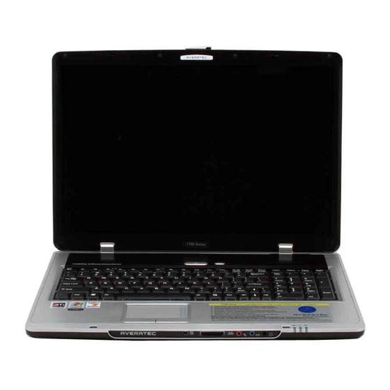
Product Overview This section provides you with the description of all the basic aspects of your Notebook. It will help you to know more about your Notebook before using it. Top-open View Press the Cover Latch to open the top cover (LCD Panel). The top-open view and descriptions follow below. - Page 26 Cover Latch This latch will lock the LCD cover with the main system when closing your Notebook PC. Rubber Pads Protects your Notebook PC when closing the LCD cover. Power Button Power Button: To turn your Notebook power ON and OFF.
- Page 27 Getting Started Status LED’s Num Lock: Glowing Blue when the Num Lock function is activated. Caps Lock: Glowing Blue when the Caps Lock function is activated. Scroll Lock: Glowing Blue when the Scroll Lock function is activated. Hard Disk In-use: Glowing Blue when the Notebook PC is accessing the hard disk drive.
-
Page 28: Front View
Front View Cover Latch (External View) Press Cover Latch to the right and lift the cover. IEEE 1394 FIREWIRE The IEEE 1394 FireWire port is a high-speed bus that allows you to connect high -end digital devices such as digital video cameras, camcorders, etc. for high speed file transfer. - Page 29 Status LED Battery: Glowing Green when recharging. Battery LED goes out when recharging is complete or when the AC adapter is disconnected. Glowing Orange when the battery is in low battery status. Blinking Orange if the battery is no longer operating correctly and needs to be replaced.
-
Page 30: Right-Side View
Right-side View Express Card Slot The computer provides an Express Card slot. Card interface is smaller and faster than the PC Card (PCMCIA) interface. The Express Card technology takes advantage of the scalable, high-bandwidth serial PCI Express and USB 2.0 interfaces. PC Card Slot (PCMCIA) The computer provides a PC card slot to support one Type-II PC card for expansion functions, such as LAN/WLAN, WWAN/WMAX, EVDO/Edge,... - Page 31 System Vents The system vents are designed to cool the system. DO NOT block the ventilator as this blocks air circulation. External CRT/VGA Port The 15-pin D sub VGA port allows you to connect an external CRT monitor, or LCD other standard VGA-compatible device (such as a projector). 2-12 Getting Started...
-
Page 32: Left-Side View
Left-side View USB Ports The USB 2.0 port allows you to connect USB-interface peripheral devices, such as external mouse, keyboard, portable hard disk drives, printer and more. Optical Disc Drive This notebook supports a CD/DVD+/-RW with Dual Layer burning. The optical device allows you to use a CD/DVD disc for installing software, accessing data and playing music and movies on the computer. -
Page 33: Rear View
Rear View Kensington Lock This port is used to lock the computer to a specific location with a cable that supports the Kensington lock. Power Connector Connects the AC adapter and external power to the computer. RJ-11 Connector The computer provides a built-in modem that allows you to connect a telephone line through this connector. -
Page 34: Bottom View
Bottom View Battery Release Lever The battery release lever is used to remove the battery pack from the system. Press the lever with one hand and pull the battery pack out carefully with the other hand. Battery Lock/Unlock Switch The battery cannot be removed when the switch is positioned in the locked position. -
Page 35: Power Management
Power Management AC Adapter Please note that it is strongly recommended to connect the AC adapter and use the AC power while using your Notebook for the first time. When the AC adapter is connected, the battery will be charging immediately. Note that the AC adapter included in the package is approved for your Notebook;... -
Page 36: Disconnecting The Ac Power
Disconnecting the AC Power When you disconnect the AC adapter, you should: Unplug the power cord from the electrical outlet first. Unplug the connector from the Notebook. Disconnect the power cord and the connector of AC adapter. When unplugging the power cord, always hold the connector part of the cord. -
Page 37: Battery Pack
Battery Pack This Notebook is equipped with a high-capacity Li-ion Battery pack. The rechargeable Li-ion battery pack provides internal power source of the Notebook. A fully charged battery pack can supply power to the Notebook approximately up to 2 hours. Battery life will vary depending on your usage. Removing the Battery Pack 1. - Page 38 Getting Started 2-19...
- Page 39 Replacing the Battery Pack Insert the right side of battery pack into the compartment. Slightly slide and press the battery pack into place. After the right side of the battery pack fits into the right track, then slightly press the left side of battery pack into the battery chamber. Make sure the Lock/Unlock Switch is in the Locked position.
-
Page 40: Using The Battery Pack
Using the Battery Pack Battery Safety Tips Replacing or handling the batte ry incorrectly may present a risk of fire or explosion, which could cause serious injury. Only replace the main battery pack with the same or equivalent type of battery. -
Page 41: Charging The Battery Pack
Charging the Battery Pack The battery pack can be recharged while it is installed in the Notebook. Please pay attention to the following tips bef ore recharging the battery: If a charged battery pack is not available, save your work and close all running programs and shut down the system or Save-to-Disk. -
Page 42: Memory Module Installation
Getting Started Memory Module Installation 1. Memory Module Compartment 2-23... -
Page 43: Installing Memory Module Process
Installing Memory module process Align the memory module in the DIMM socket. There are 2 DIMM sockets on the system motherboard. Warning The memory module can only fit in one direction due to the keyed notch. Wrong orientation will cause improper installation and may damage the memory module or DIMM socket. - Page 44 Getting Started 2. Gently push down on the memory module until the metal-locking levers on each side of the DIMM socket is fastened. 2-25...
- Page 45 Getting Started 3. If you have more than one memory module, align the 2 memory module to the empty DIMM socket. 2-26...
- Page 46 Getting Started 4. Gently push down on the memory module until the metal-locking levers on each side of the DIMM socket is fastened. 2-27...
-
Page 47: Basic Operations
Basic Operations If you are a beginner to Notebook s, please read t he following tips to make yourself safe and comfortable during the operations. Safety and Comfort Tips The Notebook is a portable computing platform that allows you to work anywhere. However, choosing a good workspace is important if you have to work with your Notebook for long periods of time. -
Page 48: Knowing The Keyboard
Please keep the following tips in mind when operating. Change your posture frequently. Stretch and exercise you body regularly. Remember to take breaks after working for a period of time. Knowing the Keyboard The Notebook’s keyboard provides all the functions of a full-sized 103-key keyboard and the additional Fn keys for specific functions on the Notebook. -
Page 49: Typewriter Keys
Typewriter Keys Typewriter Keys The function of the Typewriter keys is the major function of the keyboard, which is similar to the keys on a typewriter. It also provides several keys for special purposes, such as the [Ctrl], [Alt] and [Esc] key. When the “lock keys”... -
Page 50: Cursor Keys
Cursor Keys The keyboard provides four cursor (arrow) keys and [ Home], [PgUp], [PgDn], [End] keys at the lower right corner, which are used to control the cursor movement. Move the cursor left for one space. Move the cursor right for one space. Move the cursor up for one line. -
Page 51: Numeric Keys
The Backspace key, [Ins] and [Del] keys at upper right corner are typically used for editing purposes. This key is used to switch the typing mode between “insert” and “overtype” modes. Press this key to delete one character to the right of the cursor and move the following text left for one space. -
Page 52: Function Keys
Function Keys Windows Keys You can find the Windows Logo key ( on the keyboard, which are used to perform Windows-specific functions, such as launching the Start and shortcut menus. For more information on these two keys, please refer to your Windows manual or online help. ... -
Page 53: Knowing The Touchpad
Knowing the Touchpad The integrated touchpad in your Notebook is a pointing device that is compatible with standard mouse, allowing you to control the Notebook by pointing the location of the cursor on the screen and making selections with its two buttons. ... -
Page 54: Using The Touchpad
Using the Touchpad Read the following description to learn how to use the touchpad: Positioning and Moving Place your finger on the touchpad (usually using the forefinger), and the rectangular pad will act as a miniature duplicate of your display. When you move your fingertip across the pad, the cursor on the screen will move simultaneously in the same direction. - Page 55 Getting Started desired location; finally, release the left button to finish the drag-and-drop operation. Configuring the Touchpad You can customize the pointing device to meet your personal needs. For example, if you are a left-hand user, you may want to swap the functions of the two buttons.
-
Page 56: About Hard Disk Drive
About The Hard Disk Drive Your Notebook is equipped with a high-speed 2.5-inch IDE (Integrated Drive Electronics) hard disk drive. The hard disk drive is a storage device with much higher speed and larger capacity than other storage devices, such as a fl oppy disk drive and optical storage devices. -
Page 57: Using The Optical Disc Drive
Using the Optical Disc Drive Your Notebook is equipped with an optical storage device, which is known as the DVD Dual Layer drive. DVD Dual Drive: A dual format recorder, allows you to record both the +R DL, –R/RW and +R/RW formats. It also supports: CD-RW, CD-R, CD, DVD formats. - Page 58 Inserting a CD/DVD The following describes the general procedure when operating the optical disc drive. Confirm that the Notebook is turned on. Press the Eject Button on the drive’s panel and the CD tray will slide out partially. Then, gently pull the tray out until fully extended. Place your CD in the tray with its label facing up.
-
Page 59: Removing The Cd
Removing the CD Press the Eject Button on the drive’s panel and the CD tray will slide out partially. Then, gently pull the tray out until fully extended. Hold the CD by its edge with your fingers and lift it up from the tray. Push the tray back into the drive. -
Page 60: Customizing This Notebook
Chapter 1 Chapter 2 Customizing this Notebook Chapter 3 Chapter 4 Preface General Introductions Getting Started BIOS Setup... -
Page 61: Connecting The External Devices
Connecting External Devices The I/O (input/output) ports o n the Notebook allow you to connect peripheral devices. IEEE 1394 Device Modem Mouse/ Keyboard Printer Customizing this Notebook Speakers/ Earphones Microphone Monitor WebCam Television... -
Page 62: Connecting The Peripheral Devices
Connecting Peripheral Devices Connecting an External Mouse You can connect a n external mouse to your Notebook through the USB port. Since there is no PS/2 port available on your Notebook, and you only have a mouse with a PS/2 connector, please purchase a PS/2-USB connector first. To connect the mouse: Turn on the Notebook and install the mouse driver. -
Page 63: Connecting A Printer
Connecting a WebCam You can connect a WebCam to your Notebook through the USB port: Turn on the Notebook and install the WebCam driver. Connect your WebCam to the Notebook. The Notebook may auto detect your WebCam driver and enable the WebCam function. - Page 64 Connecting an External Monitor or TV You can connect an external monitor to your Notebook through the external VGA port for a larger view with higher resolution. To connect the monitor: Make sure that the Notebook is turned off. Plug the monitor’s D-type connector into the Notebook’s VGA port. Connect the monitor ’s power cord and turn on the monitor.
-
Page 65: Connecting The Communication Devices
Connecting Communication Devices Using a LAN The RJ -45 connector of the Notebook allows you to connect LAN (local area network) devices, such as a hub, switch and gateway, to build a network connection. The built-in 10/100/1000 Gigabit LAN module supports data transfer rate up to 1000Mbps. -
Page 66: Installing The Pc Card
PC (PCMCIA) Card Installation The PC card slot of your Notebook allows you to install comprehensive Type -II PC cards that support various functio ns including: memory cards, etc. The following instruction provides you with a basic installation for the PC card, including how to install and remove it. -
Page 67: Removing The Pc Card
Removing the PCMCIA Card Press the Eject Button to make it stretch out. Push the Eject Button and the PC card will slide out. Pull it out of the slot. Before removing the PC card, you should stop the device in the Windows operating system. -
Page 68: Express Card Installation
PC Express Card Installation This computer provides a PC Express Card slot. The new PC Express Card interface is smaller and faster than the PC (PCMCIA) Card interface. The PC Express Card technology takes advantage of the scalable, high-bandwidth serial PCI Express and USB 2.0 interfaces. -
Page 69: Safely Remove Hardware
Customizing this Notebook Safely Remove Hardware If you connect any peripheral device to your system, the Safely Remove Hardware icon ( ) will appear on the taskbar. Double-click the icon to bring up the Safely Remove Hardware dialog box. You can see all connected peripheral devices here. -
Page 70: Bios Setup
Chapter 1 Chapter 2 Customizing this Notebook Chapter 3 Chapter 4 Preface General Introductions Getting Started BIOS Setup... -
Page 71: About Bios Setup
About BIOS Setup When to Use BIOS Setup? You may need to run the BIOS Setup when: An error message appears on the screen during the system boot up and requests you to run SETUP. You want to change the default settings for customized features. ... -
Page 72: Control Keys
Control Keys You can use only the keyboard to control the cursor in the BIOS Setup Utility. Press left arrow to select one menu title. Press right arrow to select one menu title. Press up arrow to select one item under the menu title. -
Page 73: Bios Setup Menu
BIOS Setup BIOS Setup Menu Once you enter the BIOS Setup Utility, the Main menu will appear on the screen. The Main menu displays the system information, including the basic configuration. Main menu Shows System Overview information about the BIOS version, CPU features, Memory size and setting of System Time and Date. -
Page 74: Main Menu
Main menu System Overview System Overview will show you the BIOS version and other information about its build date and update notes. Following this is CPU information about its Type and Speed. System Time This item allows you to set the system time. The system clock will go on no matter if you shut down the PC or go into sleep mode. - Page 75 System Date This item allows you to set the system date. [day:month:date:year]. Day of the week, from Sun to Sat, which is determined by BIOS (read-only). Month The month from 01 (January) to 12 (December). Date The date from 01 to 31. Year The year can be adjusted by users.
-
Page 76: Advanced Menu
BIOS Setup Advanced menu Advanced Settings Primary/Secondary IDE Master These items display the types of the primary/secondary master IDE devices installed in the Notebook. Press [Enter] to bring up a window showing the detailed information of the device, including the device name, vendor, LBA mode, PIO mode and more. - Page 77 BIOS Setup Legacy USB Support If you want to use an external USB device, like a mouse, keyboard or portable disk, in a Non-Windows environment, or boot your system with an external USB device, you should enable this function by selecting Enabled.
-
Page 78: Boot Menu
BIOS Setup Boot menu Quiet Boot This item enables you to show the Averatec logo on the boot-up screen. Settings options: Disabled and Enabled. The default setting is Enabled. 1st, 2nd and 3rd Boot Device The three items allow you to set the sequence of boot devices where BIOS... -
Page 79: Security Menu
BIOS Setup Security menu Security Settings Change Supervisor/User Password When you select this function, a message box will appear on the screen as below: Enter New Password Type the password you want, up to six characters in length and press [Enter]. - Page 80 When the Supervisor Password is set, the new items User Access Level and Password Check will be added in the menu. You can define further access settings rights in the User Access Level item. Setting options: No Access, View Only, Limited and Full Access. The Password Check item is used to specify the type of BIOS password protection that is implemented.
-
Page 81: Exit Menu
BIOS Setup Exit menu Save Changes and Exit Save the changes you have made and exit the utility. Discard Changes and Exit Exit the utility without saving the changes you have made. Discard Changes Abandon your changes and reload the previous configuration before running the utility.