
Related Manuals for KTI Networks KC-350-C


Summary of Contents for KTI Networks KC-350-C
- Page 1 PoE Powered 10/100BASE-TX to 100BASE-FX Media Converters KC-350 series Installation Guide DOC.171215A...
- Page 2 (C) 2017 KTI Networks Inc. All rights reserved. No part of this documentation may be reproduced in any form or by any means or used to make any directive work (such as translation or transformation) without permission from KTI Networks Inc.
- Page 3 The information contained in this document is subject to change without prior notice. Copyright (C) All Rights Reserved. TRADEMARKS Ethernet is a registered trademark of Xerox Corp. FCC NOTICE This device complies with Class B Part 15 the FCC Rules. Operation is subject to the following two conditions: (1) This device may not cause harmful interference, and (2) this device must accept any interference received including the interference that may cause.
- Page 4 Table of Contents 1. Introduction ..........................5 1.1 Key Features ....................... 5 1.2 Specifications ...................... 6 1.3 Optical Specifications ..................10 1.4 Special Functions ....................11 1.4.1 Auto MDI/MDI-X Function ................11 1.4.2 Auto-negotiation Function ................11 1.4.3 Far End Fault Function ................... 11 1.4.4 Link Fault Pass Through Function ..............
-
Page 5: Key Features
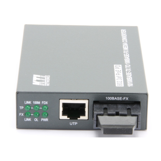
1. Introduction The 10/100BASE-TX to 100BASE-FX media converter series provides a media conversion allowing high-speed integration of fiber optic and twisted-pair segments. With 10BASE-T and 100BASE-TX support, the converters provide seamless translation between Ethernet and Fast Ethernet networks. Because of 802.3af compliance, the converters can draw the power via Cat.5 cable connected to a PoE PSE switch or mid-span injector in addition to being powered by typical external power adapter. -
Page 6: Specifications
1.2 Specifications Twisted-Pair Interface (TP Port) Connector Shielded RJ-45 Pin Assignments Auto MDI/MDI-X detection Signal Compliance IEEE 802.3 10BASE-T, 802.3u 100BASE-TX Data Speed 10Mbps or 100Mbps Duplex Mode Half-duplex or Full-duplex Configuration Auto-negotiation capable and optional forced manual settings Cable Types 10Mbps - Category 3, 4, or 5 UTP 100Mbps - Category 5 UTP Supported Link Distance... - Page 7 Fiber Optic Interface (FX Port) Signal Compliance IEEE 802.3u 100BASE-FX Connector SC, ST or Single SC Data Speed 100Mbps Duplex Mode Full-duplex and optional half duplex Multimode (MMF) - 50/125, 62.5/125 m Cable Types Single mode (SMF) - 9/125 m Supported Link Distance MMF up to 2km SMF up to 100km...
- Page 8 LED Indicators DISPLAY STATE INTERPRETATION Power status Power on Power off TP LINK TP port link status Link up and no traffic Link fault Blink Rx/Tx activities TP 100M TP port speed status ON 100Mbps 10Mbps TP FDX TP port duplex status ON Full duplex Half duplex Blink...
- Page 9 - IEEE 802.3 standard packets - IEEE 802.1Q VLAN tagged packets Packet Length Up to 1522 bytes at store-and-forward mode No limit at smart-forward mode 100to100 Flow Control Back-pressure for half-duplex mode 802.3x pause-frame base for full duplex mode Mechanical Dimension 23mm x 72.5mm x 108mm (LxWxD) Housing...
-
Page 10: Optical Specifications
1.3 Optical Specifications The media converter series provides the following fiber options: Model: KC-350-X Duplex Fiber Series Port Fiber Wavelength Tx Power Rx Sensitivity Rx Max. 1310nm -20 ~ -14dBm -32dBm -8dBm 1310nm -20 ~ -14dBm -31dBm 0dBm SL2 SC 1310nm -15 ~ -7dBm -32dBm... -
Page 11: Special Functions
1.4 Special Functions 1.4.1 Auto MDI/MDI-X Function This function allows the TP port to auto-detect the twisted-pair signals and adapts itself to form a valid MDI to MDI-X connection with the remote connected device automatically. 1.4.2 Auto-negotiation Function When TP port is set on Auto-negotiation mode (SW1: ON), it is featured with auto-negotiation function and full capability. -
Page 12: Link Fault Pass Through Function
1.4.4 Link Fault Pass Through Function When this function is enabled, a link fault detected on the TP port will force a link down on the FX port. Similarly, a link fault detected on the FX port will also force a link down on the TP port. As illustrated in the following figure, this function allows passing TP link fault to the remote link partner and makes the converter like a TP cable extender. -
Page 13: Safety Cautions
2. Installation 2.1 Unpacking Check that the following components have been included: Installation guide (or contained in the product CD) The 10/100 Media Converter If any item is found missing or damaged, please contact your local reseller for replacement. 2.2 Safety Cautions To reduce the risk of bodily injury, electrical shock, fires, and damage to the product, observe the following precautions. -
Page 14: Mounting The Device
2.3 Mounting the Device Desktop Mounting The media converter can be mounted on a desktop or shelf. Make sure that there is proper heat dissipation from and adequate ventilation around the device. Do not place heavy objects on the device. Wall Mounting The media converter also can be mounted on a wall. -
Page 15: Powered By Poe Over Cat.5
2.4 Powered by PoE over Cat.5 Power supply by a Mid-Span PoE Injector The following figure illustrates the converter is powered by the PoE delivered from a remote mid-span PoE injector over Cat.5. Power supply by a PoE PSE Switched Port The following figure illustrates the converter is powered by the PoE delivered from a remote PoE PSE switch over Cat.5. -
Page 16: Powered By External Power Adapter
2.5 Powered by External Power Adapter The converter can support being powered by an external power adapter as an alternative when PoE power is not available on Cat.5. Before you begin the installation, check the AC voltage of your area. The AC power adapter, which is used to supply the DC power for the unit should have the AC voltage matching the commercial power voltage in your area. -
Page 17: Making Tp Port Connection
2.6 Making TP Port Connection TP port is featured to support connection to: Auto-negotiation devices Auto-negotiation incapable 10BASE-T devices Auto-negotiation incapable 100BASE-TX devices Network Cables 10BASE-T: 4-pair UTP Cat. 3,4,5, EIA/TIA- 568 100-ohm STP 100BASE-TX: 4-pair UTP Cat. 5, EIA/TIA-568 100-ohm STP Link distance: Up to 100 meters Configuration Setup... -
Page 18: Making Fx Port Connection
2.7 Making FX Port Connection FX port operates on 100Mbps and full duplex (factory default). A variety of fiber options is provided as follows: Model: KC-350-X Duplex Fiber Series Connector Wavelength Fiber Ref. distance 1310nm Duplex MMF 1310nm Duplex MMF 1310nm Duplex SMF 20km... - Page 19 Single Fiber Bi-Di WDM Series Connector Wavelength Fiber Ref. Distance W3520 Bi-Di SC Tx 1310nm Single SMF 20km Rx 1550nm W5320 Bi-Di SC Tx 1550nm Single SMF 20km Rx 1310nm W3540 Bi-Di SC Tx 1310nm Single SMF 40km Rx 1550nm W5340 Bi-Di SC Tx 1550nm...
-
Page 20: Led Indicators
2.8 LED Indicators Link Fault Pass Through Function is disabled Display Status Interpretation Power status Power on Power off TP LINK TP port link status Link up and no traffic Link fault Blink Rx/Tx activities TP 100M TP port speed status On 100Mbps 10Mbps TP FDX... -
Page 21: Optional Configuration Settings
3. Optional Configuration Settings The media converter provides additional configuration settings which are user-inaccessible. The settings are built on the board inside the product case. The settings are provided for technical installers to adapt the converter to fit some specific application needs. 3.1 User Inaccessible Jumpers The setting jumpers are not accessible by users generally. -
Page 22: Forwarding Mode Setting Jp
3.1.1 Forwarding Mode Setting JP1 The following table lists the forward method used in different TP to FX conversions: JP1 Setting TP port to/from FX port Forward method Store-and-forward 10BASE-T to 100BASE-FX Store and forward 100BASE-TX to 100BASE-FX Store and forward Smart-forward 10BASE-T to 100BASE-FX Store and forward... -
Page 23: X Function Setting Jp
3.1.2 802.3x Function Setting JP2 IEEE 802.3x function is the flow control method used for full duplex operation on TP port and FX port under store and forward mode. This method uses pause frames for one port to stop further transmission from its link partner.