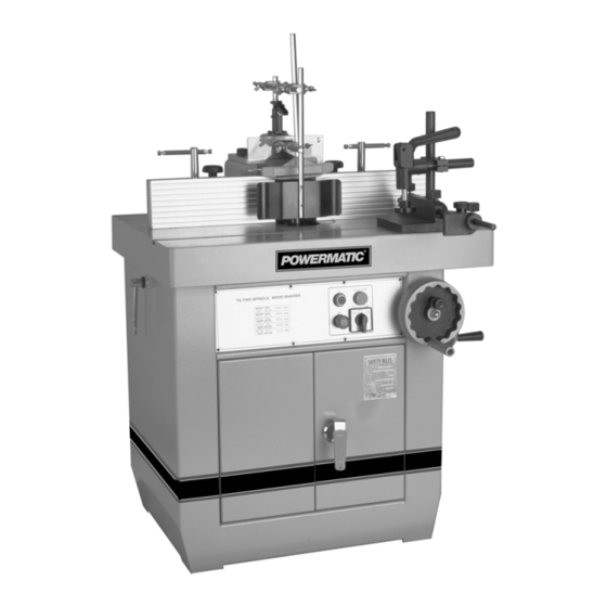
Powermatic Wood Shaper 29 Instruction Manual And Parts List
Wood shaper
Hide thumbs
Also See for Wood Shaper 29:
- Instruction manual & parts list (28 pages) ,
- Instruction manual & parts list (29 pages)

Related Manuals for Powermatic Wood Shaper 29


Summary of Contents for Powermatic Wood Shaper 29
- Page 1 WOOD SHAPER Model 29 Instruction Manual & Parts List M-0460218 (800) 274-6848 www.powermatic.com...
-
Page 2: More Information
This manual has been prepared for the owner and operators of a Powermatic Model 29 Shaper. Its purpose, aside from machine operation, is to promote safety through the use of accepted correct operating and maintenance procedures. Completely read the safety and maintenance instructions before operating or servicing the machine. -
Page 3: Table Of Contents
TABLE OF CONTENTS SAFETY RULES: General ... 4 Specific ... 4 RECEIVING THE SHAPER ... 6 INSTALLATION ... 6 Electrical Wiring ... 6 ASSEMBLY: Fence Assembly ... 6 Miter Gauge/Clamp Assembly ... 7 ADJUSTMENTS: Belt Adjustment/Speed Change ... 7 Spindle Installation & Replacement ... 8 Tilting the Spindle ... -
Page 4: Safety Rules: General
GENERAL SAFETY RULES READ THE MANUAL: Always read the owner's manual carefully before attempting to use the ma- chine. Know the limitations and hazards associated with its use. INSTALLATION: If mounting machine to the floor, use high quality anchor bolts through the mounting holes on the base. - Page 5 MISUSE: Do not use this shaper for other than its intended use. If used for other purposes, POWERMATIC disclaims any real or implied warranty and holds itself harmless for any injury which may result from that use.
-
Page 6: Receiving The Shaper
RECEIVING THE SHAPER Carefully unpack the shaper and any loose items from the wood crate and inspect for damage. Any dam- age should be reported to your distributor and ship- ping agent immediately. Before proceeding further, read your manual thoroughly to familiarize yourself with proper assembly, maintenance and safety pro- cedures. -
Page 7: Miter Gauge/Clamp Assembly
FIGURE 5 Mount the dust hood (J) to the rear of the fence body (A) with the four cross screws, Figure 6. FIGURE 6 MITER GAUGE/CLAMP ASSEMBLY The miter gauge and clamp are used for shaping the end of stock. To assemble the miter gauge: Assemble miter gauge (A) by placing bottom screw into hole on bar (B) and screwing knob and washer onto threaded rod (C), Figure 7. -
Page 8: Spindle Installation & Replacement
FIGURE 9 SPINDLE INSTALLATION & REPLACEMENT The Model 29 can use interchangeable spindles as well as router bits. To install the spindle, proceed as follows: Disconnect machine from power source. Lock the main shaft by opening the rear door in the cabinet and pulling out the knob (A), Figure 10, and rotating it to the right until it locks in place. -
Page 9: Raising & Lowering The Spindle
FIGURE 13 RAISING & LOWERING SPINDLE Loosen the small handwheel (K), Figure 13. Turn large handwheel (L) until spindle reaches the desired height. Retighten small handwheel (K). INSTALLING CUTTERS Disconnect machine from power source. Lock the main shaft (see Figure 10). Set the desired cutterhead (A) on the spindle, Figure 14, making sure of the proper rotation direc- tion (refer to illustration in "Safety Rules"). -
Page 10: Work Hold-Downs & Safety Shield
Each half of the aluminum fence should be adjusted as close to the cutterhead as possible without inter- fering with it. Each can be moved independently de- pending on the type of work to be done: Loosen the knob (D) on the connection plate and slide aluminum fence (E) to position, Figure 16. -
Page 11: Position Of Collars
When the shaping operation removes the en- tire edge of the stock, e.g. in jointing or making a full bead, the shaped edge will not be supported by the outfeed fence when both fences are in line, Figure 20a. In this case, the stock should be advanced to the po- sition shown in Figure 20a and stopped. -
Page 12: Miter Gauge
FIGURE 24 NOTE: It is advisable to place the cutter as low as possible on the spindle to reduce spindle deflection and ensure the best possible finish. Also make sure that the contacting surfaces of the cutter are smooth, clean and without dents. MITER GAUGE The miter gauge is used for shaping the end of stock, usually requiring removal of the fence. -
Page 13: Maintenance
MAINTENANCE Item Position Table Opening Connection Plate Main Shaft Apply a drop of light machine oil occasionally on the ledge and wall of the table opening to facilitate the changing of table inserts. The bearings in the motor are sealed for life and do not require lubrication. -
Page 14: Trouble Shooting
Trouble-Shooting for Model 29 Shaper PROBLEM POSSIBLE CAUSE Shaper will not start. 1. Fuse blown or circuit breaker tripped. 2. Cord damaged. Overload kicks out 1. Extension cord too light or too long. frequently. 2. Stock being fed too quickly. 3. - Page 15 Trouble-Shooting for Model 29 Shaper PROBLEM POSSIBLE CAUSE Cuts not smooth. 1. Wrong R.P.M. 2. Feed too fast. 3. Working against grain. 4. Cutting too deep. Spindle does not raise 1. Sawdust and dirt in raising mechanisms. freely. (continued) SOLUTION 1.
- Page 16 PARTS LIST: Fence Assembly (29 Shaper) NO. PART NO. DESCRIPTION 6292984 CHUTE, DUST 6292985 SCREW, HEX. SOC. SET M8 X 20 6292986 KNOB, ADJUSTMENT 6292987 PLATE 6292988 SCREW, ADJ. 6292989 6292990 HANDLE, LOCK 6292991 WASHER 6292992 CAP, R.H. 6292993 BLOCK, R.H. 6292994 BLOCK, L.H.
-
Page 17: Fence Assembly
Fence Assembly (29 Shaper) - Page 18 PARTS LIST: Spindle Assembly (29 Shaper) NO. PART NO. DESCRIPTION 6293033 NUT, 3/4" SPINDLE 6293034 NUT, 1" SPINDLE 6293035 NUT, 1-1/4" SPINDLE 6293036 WASHER, KEYED 6293037 SET, SPACER 3/4" 6293038 SET, SPACER 1" 6293039 SET, SPACER 1-1/4" 6293040 NUT, RETAINER 6293041 NUT, COLLET 6293042...
-
Page 19: Spindle Assembly
Spindle Assembly (29 Shaper) -
Page 20: Shaper Body & Miter Gauge Assemblies
PARTS LIST: Shaper Body & Mitre Gauge Assemblies (29 Shaper) NO. PART NO. DESCRIPTION 6293060 RING, INSERT 6293061 RING, INSERT 6293029 SCREW, HEX. SOC. HD. M5 X 12 6293062 SCREW, HEX. SOC. HD. M5 X 16 6293063 RING, INSERT 6293064 TABLE 6293065 WASHER, M12... - Page 21 Shaper Body & Mitre Gauge Assemblies (29 Shaper)
- Page 22 PARTS LIST: Tilting Frame Assembly (29 Shaper) NO. PART NO. DESCRIPTION 6293124 SCREW, HEX SOC. HD. M10 X 35 6293115 WASHER, M10 6293125 PULLEY MOTOR 6293126 BUSHING 6293127 RETAINER 6293128 SCREW, HEX. SOC. SET, M10 X 35 6293129 NUT, HEX. M10 6293130 PLATE, MOTOR 6293131...
-
Page 23: Tilting Frame Assembly
Tilting Frame Assembly (29 Shaper) -
Page 24: Electrical Schematic
ELECTRICAL SCHEMATIC: Model 29 Tilting Shaper THREE PHASE START (2-STEP SWITCH) - Page 25 ELECTRICAL SCHEMATIC: Model 29 Tilting Shaper THREE PHASE . r T...
-
Page 26: Optional Accessories
OPTIONAL ACCESSORIES Model 29 Tilting Shaper 6293198 1" Spindle Assembly, 6" under the nut. 6293199 1-1/4" Spindle Assembly, 6" under the nut. 6293200 460V transformer. - Page 27 Locating the stock number of the part(s) required from your parts manual will also expedite your order. Phone No.: (800) 274-6848 Fax No. (800) 274-6840 If you are calling from Canada, please call 800-238-4746 E-mail: powermatic@wmhtoolgroup.com Website: www.powermatic.com...
- Page 28 09/02 WMH Tool Group P.O. Box 1349 Auburn, WA 98071-1349 Phone: (800) 274-6848 Fax: (800) 274-6840 E-mail: powermatic@wmhtoolgroup.com Website: www.powermatic.com POWERMATIC ALL RIGHTS RESERVED...