Lenovo RackSwitch G8272 Installation Manual
Hide thumbs
Also See for RackSwitch G8272:
- Installation manual (118 pages) ,
- Product manual (32 pages) ,
- Quick start manual (24 pages)
Table of Contents
Advertisement
Quick Links
Download this manual
See also:
Installation Manual
Advertisement
Table of Contents

Related Manuals for Lenovo RackSwitch G8272


Summary of Contents for Lenovo RackSwitch G8272
-
Page 1: Installation Guide
Lenovo RackSwitch G8272 Installation Guide... - Page 2 Code (LAMC) document on the Documentation CD. Read the Systems Environmental Notices and Users Guide document on the Environmental Notices CD. First Edition (December 2014) © Copyright Lenovo Corporation 2014 US Government Users Restricted Rights—Use, duplication or disclosure restricted by GSA ADP Schedule Contract with Lenovo Corp.
-
Page 3: Safety
Πред да инсталира овој продукт, прочитајте информацијата за безбедност. Les sikkerhetsinformasjonen (Safety Information) før du installerer dette produktet. Przed zainstalowaniem tego produktu, należy zapoznać się z książką “Informacje dotyczace bezpieczeństwa” (Safety Information). Antes de instalar este produto, leia as Informações sobre Segurança. © Copyright Lenovo Corp. 2014 Safety... - Page 4 Systems Safety Notices document under “D005.” Be sure to read all caution and danger statements in this document before you perform the procedures. Read any additional safety information that comes with the switch or optional device before you install the device. RackSwitch G8272 Installation Guide...
- Page 5 Hazardous voltage, current, or energy levels are present inside any component that has this label attached. Do not open any cover or barrier that contains this label. (L001) DANGER Rack-mounted devices are not to be used as shelves or work spaces. (L002) © Copyright Lenovo Corp. 2014 Safety...
- Page 6 It is the responsibility of the customer to ensure that the outlet is correctly wired and grounded to prevent an electrical shock. (D004) RackSwitch G8272 Installation Guide...
- Page 7 Electrical voltage and current from power, telephone, and communication cables are hazardous. To avoid a shock hazard: • Connect power to this unit only with the Lenovo provided power cord. Do not use the Lenovo provided power cord for any other product. •...
- Page 8 Class 1 power levels. For this reason, never look into the end of an optical fiber cable or open receptacle. (C027) CAUTION: This product contains a Class 1M laser. Do not view directly with optical instruments. (C028) RackSwitch G8272 Installation Guide...
- Page 9 It is the responsibility of the customer to ensure that the outlet is correctly wired and grounded to prevent an electrical shock. (R001 part 1 of 2) © Copyright Lenovo Corp. 2014 Safety...
- Page 10 (R001 part 2 of 2) Important This product is also designed for IT power distribution systems with phase-to-phase voltage of 230V. Important Machinenlärminformations-Verordnung—3. GPSGV, der höchste Shalldruckpegel beträgt 70 dB (A) oder weniger. RackSwitch G8272 Installation Guide...
-
Page 11: Table Of Contents
Installing the G8272 in a Standard Equipment Rack ... 28 Installing the G8272 in a Lenovo System x or Power Rack ..30 Installing the 1U Air Duct Option. - Page 12 Russia Electromagnetic Interference (EMI) Class A Statement ..66 People’s Republic of China Class A Electronic Emission Statement . . . 66 Taiwan Class A compliance Statement ....66 RackSwitch G8272 Installation Guide...
-
Page 13: Chapter 1. Introduction
Chapter 4, “Initializing the G8272” page If documentation updates are available, you can download them from the Lenovo website. The switch might have features that are not described in the documentation that comes with the switch, and the documentation might be updated... -
Page 14: The Documentation Cd
Acrobat Reader software is required for reading documents on the CD. Related Documentation You can obtain up-to-date documentation for the firmware features of the switch in the documentation section of the Lenovo support website: http://support.lenovo.com/ For documentation about configuring your switch, see the Application Guide for your specific switch and its installed firmware. -
Page 15: Notices And Statements In This Document
Danger: These statements indicate situations that can be potentially lethal or extremely hazardous to you. A danger statement is placed just before the description of a potentially lethal or extremely hazardous procedure step or situation. © Copyright Lenovo Corp. 2014 Chapter 1: Introduction... -
Page 16: G8272 Features
– 2048 VLANs (802.1Q) with 4K VLAN IDs, including private VLANs – Multi-link trunking, compatible with Cisco EtherChannel – LACP (IEEE 802.3ad) – Spanning Tree (802.1D) protocol, Multiple Spanning Tree (802.1s) protocol, Rapid Spanning Tree (802.1w) protocol, with Fast Uplink Convergence – 32K forwarding database entries RackSwitch G8272 Installation Guide... - Page 17 – Layer 2 failover – Hot links – VRRP Note: The features supported on your switch depend on the specific firmware installed. Your switch features may vary slightly from those described in this overview. © Copyright Lenovo Corp. 2014 Chapter 1: Introduction...
-
Page 18: Switch Components
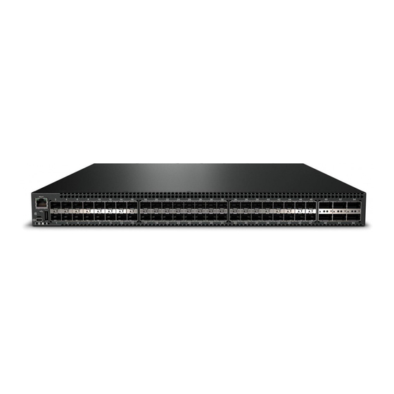
The G8272 is a 1U rack-mountable GbE switch. You can mount the switch in either the horizontal or vertical direction. The following illustrations show the features on the front and rear of the switch. Figure 1. RackSwitch G8272 front panel Mgmt Mini-USB... -
Page 19: Switching Ports
USB drive, or from the USB drive to the switch. You can also start the switch using files on the USB drive. For more information about using the USB drive, see the RackSwitch G8272 Release Notes. - Page 20 QSFP+ to four 10 GbE SFP+ breakout DAC. The SFP+ connectors on supported breakout DACs are labelled A, B, C, and D, which correspond to the first, second, third, and fourth ports in the port range. RackSwitch G8272 Installation Guide...
-
Page 21: Rear Panel
There is no power switch on the G8272; the switch unit powers up when power is supplied through the power cords. © Copyright Lenovo Corp. 2014 Chapter 1: Introduction... -
Page 22: Technical Specifications
The power specifications for the G8272 are listed in the following table. Table 5. AC power specifications Specification Measurement Number of power supplies 2 (1+1 load sharing/redundant) AC-input frequency (universal) 50 - 60 Hz AC-input voltage (universal) 100-240 VAC System power dissipation (maximum) 240.3 W RackSwitch G8272 Installation Guide... -
Page 23: Chapter 2. Installing G8272 Hardware And Options
– Vital safety information • “Installing the G8272 in a Standard Equipment Rack” on page 28 • “Installing the G8272 in a Lenovo System x or Power Rack” on page 30 • “Installing the 1U Air Duct Option” on page 34 •... -
Page 24: Before Installing The G8272
Print this page and record product information below. Keep the information in a safe place for future reference. You will need this information when you register the switch or open a service call with Lenovo. Table 6. Important product information... -
Page 25: Required Tools
Electrostatic discharge wrist strap Package Contents The basic G8272 package contains the following items: • One RackSwitch G8272 unit with rear-to-front or front-to-rear airflow. • One standard rack mount kit that includes: – Two mounting brackets – Screws to attach brackets to the switch unit –... - Page 26 Electrical voltage and current from power, telephone, and communication cables are hazardous. To avoid a shock hazard: • Connect power to this unit only with the Lenovo provided power cord. Do not use the Lenovo provided power cord for any other product. •...
- Page 27 Do not place the device on a switch cover or on a metal surface. • Take additional care when you handle devices during cold weather. Heating reduces indoor humidity and increases static electricity. © Copyright Lenovo Corp. 2014 Chapter 2: Installing G8272 Hardware and Options...
-
Page 28: Installing The G8272 In A Standard Equipment Rack
Installing the G8272 in a Standard Equipment Rack This section describes how to install the G8272 in a standard 19-inch equipment rack. For information about mounting the switch in a Lenovo System x or Power rack, see “Installing the G8272 in a Lenovo System x or Power Rack” on page The following parts are included in the standard mounting kit. - Page 29 7. Initialize the switch. See Chapter 4, “Initializing the G8272,” on page 8. If the switch is a replacement unit, set Vital Product Data (see “Configuring Vital Product Data” on page 49). © Copyright Lenovo Corp. 2014 Chapter 2: Installing G8272 Hardware and Options...
-
Page 30: Installing The G8272 In A Lenovo System X Or Power Rack
This section describes how to install the G8272 in a Lenovo System x or Power 4-post rack, such as the Lenovo e1350, using the Lenovo Adjustable 19” 4-Post Rail Kit. The kit must be purchased separately. It includes the following parts: Table 8. - Page 31 3. Use M4 screws to attach the front mounting brackets to each side of the switch. Torque the screws to approximately 2.0 newton-meters (Nm) ± 0.1 Nm (17.7 inch-pounds). © Copyright Lenovo Corp. 2014 Chapter 2: Installing G8272 Hardware and Options...
- Page 32 Torque the screws to approximately 5.7 Nm ± 0.1 Nm (50 inch-pounds). 5. Slide the rear mounting brackets into the slots available on the front mounting brackets. RackSwitch G8272 Installation Guide...
- Page 33 10. Initialize the switch. See Chapter 4, “Initializing the G8272,” on page 11. If the switch is a replacement unit, set Vital Product Data (see “Configuring Vital Product Data” on page 49). © Copyright Lenovo Corp. 2014 Chapter 2: Installing G8272 Hardware and Options...
-
Page 34: Installing The 1U Air Duct Option
Table 9. 1U air duct mounting kit Item Number Description Quantity Cable tie 1U Duct sleeve (long) Mounting bracket, right, assembly, 1U duct Mounting Bracket, left, assembly, 1U duct Foam carrier assembly Screw, slotted, M3.5, 7 mm, flanged hex head RackSwitch G8272 Installation Guide... - Page 35 (10 inch-pounds). Foam carrier snug against rear of unit Reuse mounting screws Half shear Mounting screws Note: There are additional M3.5 screws in the air duct assembly kit. © Copyright Lenovo Corp. 2014 Chapter 2: Installing G8272 Hardware and Options...
- Page 36 Air duct mounting bracket M6 screws M3.5 screws 5. Use the M3.5 screws to secure the air duct mounting bracket to the rack chassis. Torque the screws to approximately 1.1 Nm ± 0.1 Nm (10 inch-pounds). RackSwitch G8272 Installation Guide...
- Page 37 Make sure that the foam strip is oriented on top. Foam Card guides thumbscrews Side flanges 7. Use the two M4 thumbscrews to secure the air duct unit to the air duct brackets. © Copyright Lenovo Corp. 2014 Chapter 2: Installing G8272 Hardware and Options...
-
Page 38: Installing Sfp Or Sfp+ Transceivers
3. Pull up the locking lever to lock the transceiver into place. 4. Connect the cable. To remove an SFP copper transceiver, disconnect the cable, and pull down the locking lever to release the transceiver. After you remove the transceiver, replace the safety cap. RackSwitch G8272 Installation Guide... -
Page 39: Installing An Sfp Optical Transceiver
To remove an SFP optical transceiver, disconnect the fiber-optic cable, and pull down the locking lever to release the transceiver. After you remove the transceiver, replace the safety cap. © Copyright Lenovo Corp. 2014 Chapter 2: Installing G8272 Hardware and Options... -
Page 40: Installing An Sfp+ Optical Transceiver
3. Pull up the locking lever to lock the transceiver into place. 4. Connect the fiber-optic cable. To remove an SFP+ optical transceiver, disconnect the fiber-optic cable, and pull down the locking lever to release the transceiver. After you remove the transceiver, replace the safety cap. RackSwitch G8272 Installation Guide... -
Page 41: Installing A Qsfp+ Optical Transceiver
To remove a QSFP+ optical transceiver, disconnect the fiber-optic cable, and pull down the locking lever to release the transceiver. After you remove the transceiver, replace the safety cap. © Copyright Lenovo Corp. 2014 Chapter 2: Installing G8272 Hardware and Options... - Page 42 RackSwitch G8272 Installation Guide...
-
Page 43: Chapter 3. Removing And Replacing G8272 Components
The following topics are covered: • “Removing the G8272 from a Standard Equipment Rack” on page 43 • “Removing the G8272 from a Lenovo System x or Power Rack” on page 45 • “Removing the 1U Air Duct Option” on page 48 •... - Page 44 5. Loosen and remove the M4 screws attaching the mounting bracket on each side of the switch. 6. If replacing the unit with another G8272, see “Replacing the G8272” on page RackSwitch G8272 Installation Guide...
-
Page 45: Removing The G8272 From A Lenovo System X Or Power Rack
Removing the G8272 from a Lenovo System x or Power Rack This section describes how to remove the G8272 from a Lenovo System x or Power 4-post rack, such as the Lenovo e1350. To remove the G8272 from a System x or Power rack, complete the following steps: 1. - Page 46 6. Loosen and remove the M6 screws, washers, and clip nuts are used to connect the front mounting brackets to the front and rear posts in the rack. 7. Slide the G8272 out of the rack. RackSwitch G8272 Installation Guide...
- Page 47 8. Loosen and remove the M4 screws that attach the front mounting brackets to each side of the switch. 9. If replacing the unit with another G8272, see “Replacing the G8272” on page © Copyright Lenovo Corp. 2014 Chapter 3: Removing and Replacing G8272 Components...
-
Page 48: Removing The 1U Air Duct Option
Removing the 1U Air Duct Option The G8272 supports an optional 1U air duct to maximize air flow conditions in a Lenovo Power Systems Group rack. To remove an installed 1U air duct option from a 19” rack, complete the following steps. -
Page 49: Replacing The G8272
RS 8272(config)# where 1234-56X is the MTM from your old unit. Note: The MTM shown here is merely an example—use the actual MTM recorded from your old G8272 unit. © Copyright Lenovo Corp. 2014 Chapter 3: Removing and Replacing G8272 Components... - Page 50 Redundant Power Supply: Not Installed Power Faults: () Fan Faults: () Service Faults: () For more information about using the switch interface, see the Application Guide and Command Reference for your switch model and firmware version. RackSwitch G8272 Installation Guide...
-
Page 51: Chapter 4. Initializing The G8272
Redundant Power Supply through a DC to DC power cable. • Service ( ! ): Off if the system is OK, or flashing if service is required. © Copyright Lenovo Corp. 2014... - Page 52 PPCBoot 0.0.0.10 (new flash) Memory Test (0x00) ......PASSED Lenovo RS 8272 Jan 1 00:01:27 2011: NOTICE-5:Interface Oper Status Indication - Port 7 State UP Password: At the prompt, type the switch password and press Enter. The default is admin. RackSwitch G8272 Installation Guide...
-
Page 53: Default Configuration
In addition, you can configure the switch for management using an SNMP-based network management system or a web-browser. For more information about using the CLI, see the Command Reference guide for your specific switch and firmware version. © Copyright Lenovo Corp. 2014 Chapter 4: Initializing the G8272... -
Page 54: Updating Firmware
Updating Firmware If firmware updates are available, you can download them from the Lenovo website. The switch might have features that are not described in the documentation that comes with the switch, and the documentation might be updated occasionally to include information about those features, or technical updates might be available to provide additional information that is not included in the switch documentation. -
Page 55: Chapter 5. Troubleshooting
If you have problems accessing the switch or working with the firmware, see the Command Reference for the switch. For information about calling Lenovo for service, see Appendix A, “Getting Help and Technical Assistance”... - Page 56 RackSwitch G8272 Installation Guide...
-
Page 57: Appendix A. Getting Help And Technical Assistance
If you need help, service, or technical assistance or just want more information about Lenovo products, you will find a wide variety of sources available from Lenovo to assist you. This section contains information about where to go for additional information about Lenovo and Lenovo products, what to do if you experience a problem with your system, and whom to call for service, if it is necessary. -
Page 58: Using The Documentation
Using the Documentation Information about your Lenovo system and preinstalled software, if any, or optional device is available in the documentation that comes with the product. That documentation can include printed documents, online documents, readme files, and help files. RackSwitch G8272 Installation Guide... -
Page 59: Appendix B. Notices
Consult your local Lenovo representative for information on the products and services currently available in your area. Any reference to a Lenovo product, program, or service is not intended to state or imply that only that Lenovo product, program, or service may be used. Any functionally equivalent product, program, or service that does not infringe any Lenovo intellectual property right may be used instead. -
Page 60: Trademarks
Trademarks Lenovo, the Lenovo logo, Flex System, System x, NeXtScale System, and X-Architecture are trademarks of Lenovo in the United States, other countries, or both. Adobe and PostScript are either registered trademarks or trademarks of Adobe Systems Incorporated in the United States and/or other countries. -
Page 61: Important Notes
(TBW). A device that has exceeded this limit might fail to respond to system-generated commands or might be incapable of being written to. Lenovo is not responsible for replacement of a device that has exceeded its maximum guaranteed number of program/erase cycles, as documented in the Official Published Specifications for the device. -
Page 62: Particulate Contamination
If Lenovo determines that the levels of particulates or gases in your environment have caused damage to the device, Lenovo may condition provision of repair or replacement of devices or parts on implementation of appropriate remedial measures to mitigate such environmental contamination. -
Page 63: Telecommunication Regulatory Statement
Properly shielded and grounded cables and connectors must be used in order to meet FCC emission limits. Lenovo is not responsible for any radio or television interference caused by using other than recommended cables and connectors or by unauthorized changes or modifications to this equipment. -
Page 64: European Union Emc Directive Conformance Statement
EU-Mitgliedsstaaten und hält die Grenzwerte der EN 55022 Klasse A ein. Um dieses sicherzustellen, sind die Geräte wie in den Handbüchern beschrieben zu installieren und zu betreiben. Des Weiteren dürfen auch nur von der Lenovo empfohlene Kabel angeschlossen werden. Lenovo übernimmt keine Verantwortung für die Einhaltung der Schutzanforderungen, wenn das Produkt ohne Zustimmung... -
Page 65: Vcci Class A Statement
Dieses Gerät ist berechtigt, in übereinstimmung mit dem Deutschen EMVG das EG-Konformitätszeichen - CE - zu führen. Verantwortlich für die Konformitätserklärung nach Paragraf 5 des EMVG ist die Lenovo (Deutschland) GmbH, Gropiusplatz 10, D-70563 Stuttgart. Informationen in Hinsicht EMVG Paragraf 4 Abs. (1) 4: Das Gerät erfüllt die Schutzanforderungen nach EN 55024 und EN 55022... -
Page 66: Japan Electronics And Information Technology Industries Association (Jeita) Statement
This is for any areas other than home. Russia Electromagnetic Interference (EMI) Class A Statement People’s Republic of China Class A Electronic Emission Statement Taiwan Class A Compliance Statement RackSwitch G8272 Installation Guide...