Table of Contents
Advertisement
Apr.2004
EXR-7
interactive arranger
TABLE OF CONTENTS
Copyright © 2004 by ROLAND CORPORATION
All rights reserved. No parts of this publication may be reproduced in any form whithout the written permission of
ROLAND CORPORATION.
10/13
16/24
SN00075
2
3
4
6
7
8
14
14
CIRCUIT DIAGRAM (PHONES)
14
15
CIRCUIT DIAGRAM (VOLUME)
15
26
28
30
32
34
36
38
40
K6018551
SERVICE NOTES
First edition
Issued by RES
Printed in Italy
EXR-7
41
42
44
46
48
50
52
54
55
54
55
54
55
56
58
Advertisement
Table of Contents

Related Manuals for Roland EXR-7


Summary of Contents for Roland EXR-7
-
Page 1: Table Of Contents
CIRCUIT DIAGRAM (MAIN 5/7 - D-BEAM section) CIRCUIT DIAGRAM (MAIN 6/7 - FDC section) Copyright © 2004 by ROLAND CORPORATION All rights reserved. No parts of this publication may be reproduced in any form whithout the written permission of ROLAND CORPORATION. -
Page 2: Specifications
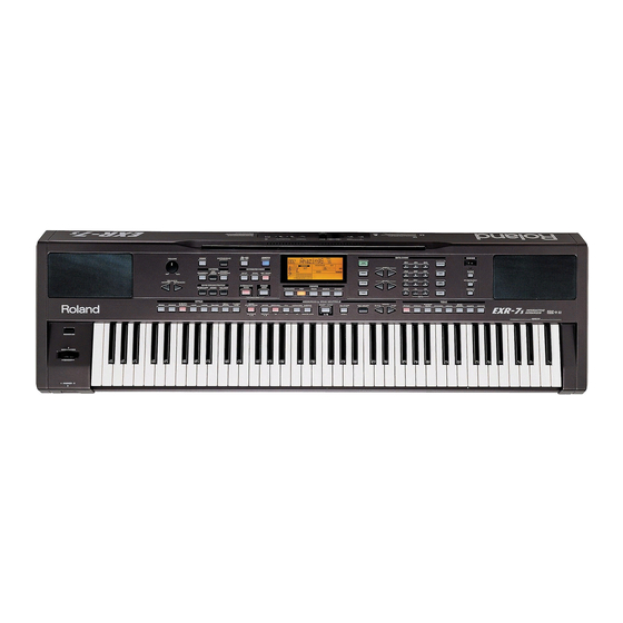
Apr.2004 SPECIFICATIONS EXR-7 Interactive Arranger Keyboard: 76 keys, velocity sensitive Sound source: PCM samples Max polyphony: 64 voices Tones: 551 panel sounds + 542 XG compatible voices + 256 GM2 compatible sounds Drum Kits: 20 Drum Kits, 11 XG-compatible Drum Kits + 9 GM2 compatible Drum Kits... -
Page 3: Disassembly
EXR-7 DISASSEMBLY... -
Page 4: Location Of Controls
USB SOCKET YKF45-0002 Cod. 12199584 Cod. 01459945 DC IN 12V 2.5A EXR-7 OUTPUT USE ROLAND PSB-4U FOOTSWITCH MIDI L / MONO ADAPTOR ONLY THIS DEVICE COMPLIES WITH PART 15 OF THE The D Beam has been licensed by Interactive Light, Inc FCC RULES. -
Page 5: Exploded View (Top)
7775310000 SILKSCREENED PLEXIGLASS EXR-3/5 7775705000 PHONES PCB ASSY EXR-7 7775702000 RIGHT CONTROL PCB ASSY EXR-7 K2268188 RIGHT VIBRATION DUMPER HLC/30 GREY EXR-7 K2248187 RIGHT/LEFT LOUDSPEAKER GRILL EXR-5 K2268189 LEFT VIBRATION DUMPER HLC/30 GREY EXR-7 7775704000 LEFT CONTROL PCB ASSY EXR-7... -
Page 6: Exploded View (Bottom)
EXR-7 EXPLODED VIEW - BOTTOM No. Part No. Description 7775710000 BLACK VARN+CONDUCTIVE BOTTOM CBNT K2418125 LOUDSPEAKER MM.130 4OHM RIF.2313 CPU PCB ASSY EXR-7 7775701000 J240910601 FLOPPY D.DRIVER JU-257A167P 22165134 BRASS BUSHING 22265242 RUBBER GUIDE BUSHING 7775720000 76 KEY KEYBOARD TP/9S... -
Page 7: Keyboard Parts List
Apr.2004 EXR-7 KEYBOARD PARTS LIST 76 KEY TP/9S KEYBOARD ASSY code 7775720000 PARTS NAME CODE KEY SPRING 22178233 NATURAL KEY C5 22578319 NATURAL KEY D6 22578328 NATURAL KEY E7 22578329 NATURAL KEY F1 22578330 NATURAL KEY G2 22578331 NATURAL KEY A3... -
Page 8: Parts List
Replacement only be a unit. CASING Q.ty K2248187 RIGHT/LEFT LOUDSPEAKER GRILL EXR-5 K2198114 PLASTIC MUSIC REST EXR-5 7775709000 VARN+SILK. KEYBOARD BLIND EXR-7 7775710000 BLACK VARN. + CUNDUCTIVE BOTTOM CBNT 7775711000 VARN.+SILK TOP CBNT EXR-7 KNOB BUTTON K2478265 BLACK KNOB 1420 E/D. 24 H.9... -
Page 9: Parts List
I.C. L4940V5 01670890 I.C. PQ3DZ53U REGULATOR J5259133 I.C. TA7805 AF J5259163 I.C. LP2950 CZ-3.3 00562601 POWER AMP LA4705 7775716000 I.C. FLEX ROM IC26 CPU EXR-7 7775717000 I.C. FLEX ROM IC51 CPU EXR-7 TRANSISTOR 15129114 TRANSISTOR 2SC-1815GR 15129136 TRANSISTOR 2SC-2878-A/B 15129602... - Page 10 Apr.2004 J5339104 ZENER DIODE EDZ7.5B 7,5V CHIP RESISTOR J3709119 RESISTOR 4.7K OHM 1/8W 5% J3919104 RESISTOR ARRAY EXB-A10E-103-J J3919107 RESISTOR ARRAY EXB-V8V-101-JV J3919108 RESISTOR ARRAY EXB-V8V-103-JV J3919109 RESISTOR ARRAY EXB-V8V-470-JV J3919116 RESISTOR ARRAY EXB-V8V-220-JV J3919115 RESISTOR ARRAY EXB-V8V-223-JV J3809127 UNINFL. RES. 22 OHM 1/4W J3809158 ININF.
- Page 11 NUT 3MA H.3 J2139102 TOOTHED WASHER I/D 3 22165134 BRASS BUSHING 00453223 LED SPACER H. 7 E.D. 5 K2268188 RIGHT VIBRATION DUMPER HLC/30 GREY EXR-7 K2268189 LEFT VIBRATION DUMPER HLC/30 GREY EXR-7 22265242 RUBBER GUIDE BUSHING K2358105 PRESSURE RUBBER 12199584...
-
Page 12: How To Save How To Version Up
Apr.2004 HOW TO SAVE HOW TO VERSION UP HOW TO SAVE – HOW TO VERSION UP Since EXR-7 has a flash memory for the System Program registration, you can update it by floppy disk. Items Required: SOFTWARE UPDATE DISK 1 EXR-7... -
Page 13: How To Update The Software
EXR-7 HOW TO UPDATE THE SOFTWARE HOW TO UPDATE THE SOFTWARE VERSION Turn the power on while keeping the buttons FUNCTION and 0 pressed. The display visualizes: Ins Dsk#1 Insert Disk 1 into the Floppy Disk Drive. Then the display visualizes:... -
Page 14: Test Mode
Apr.2004 TEST MODE The general test menu has a hierarchical structure. You can get back to each menu page or up to the MAIN MENU page. The button 0 (0 = EXIT) allows you to interrupt any test except for: Rom Test Ram Test Test... - Page 15 EXR-7 SWITCH TEST Pressing the button 1, you enter the Switch test: Press the buttons on the control panel one by one in sequence. The display visualizes the name of the button pressed and you hear a sound. After pressing each button the corresponding led lights up.
- Page 16 NOTE: In this test you cannot test the USB port. To carry out the USB test, you can connect the EXR-7 to your computer and check if the computer recognises the EXR-7 as an external drive. Go to main menu and press button 2. The display visualizes: Foot MIDI Connect a Sustain Pedal (ie.:DP-2) to EXR-7 FOOT SWITCH output.
- Page 17 EXR-7 (P3) Pitch Bender/Modulation and D-Beam Go to main menu and press button 3. The display visualizes: BendMod Db (BendMod) PITCH BENDER and Modulation TEST Pressing button 1, the display visualizes: Moving the Pitch Bender lever onwards, the value changes from OFF to ON. When releasing it, the value changes from ON to OFF.
- Page 18 Apr.2004 (FD) Floppy Disk Test Pressing button 4, the display visualizes: FD TEST Then: Insert Disk Insert an unprotected and formatted HD floppy disk into the floppy disk driver. After a few seconds the display visualizes: OK or Er The system automatically writes and reads the disk. Wait for the test result before leaving test mode: OK : if the test is successful;...
- Page 19 EXR-7 AUDIO TEST CAUTION: Make sure the instrument is powered by an adaptor SA165A-1250U-3. Pressing button 3 on the main menu, the display visualizes: Pressing button 1, the display visualizes: SINE Test procedure: Insert a stereo jack into the headphones socket;...
- Page 20 Apr.2004 If you press button 2, you hear a sine sound of 1000 Hz coming from both right and left loudspeakers and the display visualizes: 1000 Hz To exit press button 0 (Exit). If you press button 3, you hear a sine sound of 5000 Hz coming from both right and left loudspeakers and the display visualizes: 5000 Hz To exit press the button 0 (Exit) twice.
- Page 21 EXR-7 MEMORY TEST Pressing button 4 on the main menu, the display visualizes: Pressing button 1, the display visualizes: Pressing button 1 to enter Pg (IC-38), the display visualizes: WAIT Then, the display visualizes the test result: Ok: test succeeded Er: test failed To exit press button 0 (Exit).
- Page 22 Apr.2004 Press 0 twice to get back to the M1 M2 menu. Press button 2, the display visualizes: Eram Pressing button 1 (Wr), the display visualizes: Wave Rom Once the test is completed, the display visualizes the test result: Ok: test succeeded Er: test failed To exit press button 0 (Exit).
- Page 23 EXR-7...
-
Page 24: Block Diagram
Apr.2004 EXR-7 BLOCK DIAGRAM PHONES BOARD IC47 IC14 LINE CPU BOARD FOOTSWITCH MIDI OUTPUT SOUND DATA JACK LOUT GENERATION BOARD ROUT 24.576MHz IC31 PHOTO BUFFER Q4,Q17,Q18 Q2,Q3 MUTE SQUELCH CNTRL 64 M BUFF. IC24 WAVE ROM D-BEAM IC28 Control UCAS... -
Page 25: Circuit Board (Main)
Apr.2004 CIRCUIT BOARD (MAIN) View from component side... - Page 26 EXR-7 CIRCUIT BOARD (MAIN) View from solder side...
-
Page 27: Circuit Diagram (Main 1/7)
Apr.2004 EXR-7 CIRCUIT DIAGRAM (MAIN 1/7) 4X47s 4X47s 4X47s 4X47s 4X47s RA12 4X47s RA13 4X47s 33uF16s RA15 4X47s RA16 4X47s 5VREF DAN202K BENDER R115 100s R116 100s XGWAIT DAMP R117 100s HD6437016E03F 100nFs 100nFs 100nFs 100nFs 100nFs (1lot : HD64F7017F28) -
Page 28: Circuit Diagram (Main 2/7 - Xp Section)
Apr.2004 EXR-7 CIRCUIT DIAGRAM (MAIN 2/7 - XP SECTION) C306 3. 3 100nFs XWOE XW3OE WA23 W3A23 IC51 WA22 W3A22 W3A22 WD15 */D15 WA21 W3A21 W3A21 WD14 WA20 W3A20 W3A20 WD13 WA19 W3A19 W3A19 WD12 WA18 W3A18 W3A18 WD11 WA17... -
Page 29: Circuit Diagram (Main 3/7 - Key Section)
Apr.2004 EXR-7 CIRCUIT DIAGRAM (MAIN 3/7 - KEY SECTION) RA26 33uF16s EXB_A10E_103_J ELKE471FA 100nFs C406 100nFs AMPC1_2716P SSC1080F0B R253 R254 RA27 RA49 EXBV8V_220_JV EXB_A10E_103_J KSCLK MK10 SC10 BR10 PR10 To LEFT KEYB. Pcb RA28 EXB_A10E_103_J To page 32, A[0..1] To page 36, A[0..21]... -
Page 30: Circuit Diagram (Main 4/7 - Memory Section)
Apr.2004 EXR-7 CIRCUIT DIAGRAM (MAIN 4/7 - MEMORY SECTION) STYLE FLASH ROMs IC1A TC74VHC139F DQ15 DQ15 DQ14 DQ14 DQ13 DQ13 XFLASH2 DQ12 DQ12 XFLASH1 DQ11 DQ11 DQ10 DQ10 XSTYLE 1ST Style 2ND Style 16 Mbit FLASH 16 Mbit FLASH IC1C... -
Page 31: Circuit Diagram (Main 5/7 - D-Beam Section)
Apr.2004 EXR-7 CIRCUIT DIAGRAM (MAIN 5/7 - D-BEAM SECTION) R228 R229 68Ks 12Ks R230 18Ks R227 C387 TP14 100nFs 820Ks +12V R231 IC77A BK2125HM102 2K2s C386 M5223FP R233 R232 10Ks 10pFs R234 R236 R235 100s 100s 15Ks 33Ks DAP202K C421... -
Page 32: Circuit Diagram (Main 6/7 - Fdc Section)
Apr.2004 CIRCUIT DIAGRAM (MAIN 6/7 - FDC SECTION) -
Page 33: Circuit Diagram (Main 7/7 - Usb Section)
EXR-7 CIRCUIT DIAGRAM (MAIN 7/7 - USB SECTION) -
Page 34: Circuit Board (Jack)
Apr.2004 EXR-7 CIRCUIT BOARD (JACK) View from component side... -
Page 35: Circuit Diagram (Jack)
Apr.2004 EXR-7 CIRCUIT DIAGRAM (JACK) C103 100pF np0 C104 R116 10uF16BP R115 D+5V C105 YKF51-5054 R117 R118 100uF25 R119 680k 1SS133 2SC2878 IC9B D+5V FBR07HA850TB-00 M5218AL 53014_0710 IC1C DAMPER IC1D FLAT HD74LS04P NI U HD74LS04P R120 Right L eft DTA114ES... -
Page 36: Circuit Board (Right Control/D-Beam)
Apr.2004 EXR-7 CIRCUIT BOARD (RIGHT CONTROL/ D-BEAM) View from component side... -
Page 37: Circuit Diagram (Right Control/D-Beam)
Apr.2004 EXR-7 CIRCUIT DIAGRAM (RIGHT CONTROL) CIRCUIT DIAGRAM (D-BEAM) LSC0 Orange Orange Orange 1uF16 SSC0 CONTROLS PIANO SONG LSC1 100K MUSIC STRINGS Orange Green Orange ASSIST. SSC1 TLN201 TPS708 100K MUSIC ORGAN STYLE ASSIST. LSC2 IC1A SONG SAX_BRASS UPC4570HA SSC2... -
Page 38: Circuit Board (Left Control)
Apr.2004 EXR-7 CIRCUIT BOARD (LEFT CONTROL) View from component side... -
Page 39: Circuit Diagram (Left Control)
Apr.2004 EXR-7 CIRCUIT DIAGRAM (LEFT CONTROL) VLED SSC[0..11] LLSC0 RN2227 SSC0 BLLSC0 Orange Orange Orange Orange Orange ROCK VLED KEYB. TOUCH KEYBOARD ORIGINAL COVER SSC1 LLSC1 RN2227 ROCK SYNC/ ACOUSTIC DEMO TOUCH START BLLSC1 DEMO METRONOME FILL Orange Orange Orange... -
Page 40: Circuit Board (Phones)
Apr.2004 CIRCUIT BOARD (PHONES) View from component side CIRCUIT BOARD (VOLUME) View from component side CIRCUIT BOARD (SWITCH) View from component side... -
Page 41: Circuit Diagram (Switch)
EXR-7 CIRCUIT DIAGRAM (PHONES) 53014_0710 Right Le ft AGND MuteSend MuteRet MuteSend_1 MuteSend_1 MuteRet_1 YKB21_5078 To JACK PCB ASSY (CN8) MuteRet_1 JK10 YKB21_5078 100nFC CIRCUIT DIAGRAM (VOLUME) MASTER VOLUME 53015-0610 AGND VR1A RET_R RK14K1230 RET_L SEND_L SEND_R AGND VR1B RK14K1230... -
Page 42: Circuit Board (Contact Board)
Apr.2004 EXR-7 CIRCUIT BOARD (RIGHT - LEFT CONTACT w/RUBBER View from solder side View fromsolder side... -
Page 43: Circuit Diagram (Contact Board)
Apr.2004 EXR-7 CIRCUIT DIAGRAM (CONTACT BOARD) SW10 SW11 SW12 SW13 SW14 SW15 SW16 SW17 SW18 SW19 SW20 SW21 SW22 SW23 SW24 SW25 SW26 SW27 SW28 SW29 SW30 SW31 SW32 ampc1_2716p LEFT CONTACT PCB ASSY SW33 SW34 SW35 SW36 SW37 SW38...