
Related Manuals for Pitney Bowes Relay 5000


Summary of Contents for Pitney Bowes Relay 5000
- Page 1 Shipping & Mailing Inserter Relay™ 5000/6000/7000/8000 Document Inserting System Operator Guide International English Edition SV63136 Rev. A August 1, 2015...
- Page 2 Due to our continuing program of product improvement, equipment and material specifications as well as performance features are subject to change without notice. Connect+, SwiftStart, IntelliLink and E-Z Seal are trademarks or registered trademarks of Pitney Bowes. Tyvek is a registered trade- mark of Dupont.
-
Page 3: Table Of Contents
Table of Contents Contact Information List ..........v USA Contacts .................v Canada Contacts ................v Contacts in other countries .............v 1 • Introduction ............1-1 A Note to the Operator ..............1-2 About Your System ..............1-2 System Features ..............1-2 System Components ............1-2 Standard Systems .............. - Page 4 Table of Contents About System Covers ............... 2-22 Opening the Covers ............2-23 Closing the Covers ............. 2-23 About the Paper Release Knobs/Levers........2-24 About Add-On Modules ............. 2-24 3 • Basic Operation ............3-1 Connecting to Power ..............3-2 Powering Up ................3-2 Home Screen ................
- Page 5 Table of Contents 5 • Troubleshooting and Maintenance .......5-1 Adjusting Screen Brightness and Contrast ......... 5-2 Setting the Time and/or Date ............5-3 Changing the Language ............. 5-4 Refilling the Sealing Solution ............5-5 Handling Material Stoppages ............5-5 Clearing a Stoppage ............. 5-5 Resuming the Job ..............
- Page 6 Table of Contents 8 • Scanning ..............8-1 Scanning Overview ..............8-2 OMR ..................8-2 BCR ..................8-2 Physical Specifications for 2D Data Matrix Barcodes ..........8-5 Supported Square and Rectangular Formats ....... 8-5 Scanning Features ..............8-8 Supported ECC (Error Correction Code) Levels ....8-10 Setting Up a New Scan Configuration ........
- Page 7 Table of Contents Setting the OMR Scanning Area ..........8-38 Defining the First Mark Position and Code Length ....8-38 Defining the Clear Zone ............8-39 Additional Information ............... 8-40 BCR and OMR Mark Levels ............. 8-40 Basic Level ................. 8-41 Enhanced Integrity Level ............
- Page 8 This page is intentionally blank.
-
Page 9: Contact Information List
Contact Information List USA Contacts Product Name - Relay™ 5000/6000/7000/8000 • For frequently asked questions, go to: www.pb.com and click on Customer Support. • To place requests for service or training, go to: www.pb.com and click on My Account. • To order supplies and accessories, call the Supply Line at: 1.800.243.7824 or go to: www. - Page 10 This page is intentionally blank.
-
Page 11: Introduction
1 • Introduction Contents A Note to the Operator..............1-3 About Your System ..............1-3 System Features .................1-3 System Components ............. 1-3 Standard Systems ...............1-4 System Options ................1-5 Safety Information ...............1-6 Safety Information (continued) ............1-7 Warning Labels ................1-7 SV63136 Rev. A... - Page 12 This page is intentionally blank. SV63136 Rev. A...
-
Page 13: A Note To The Operator
Introduction • 1 A Note to the It is important to be familiar with this guide as it will enable you to utilize the system to its full potential, while keeping problems to a minimum. Operator NOTE: The availability of add-ons and options for your inserting system varies by region. -
Page 14: Standard Systems
1 • Introduction Standard Relay 8000 Systems Relay 7000 Relay 5000 Relay 6000 (HCSF is optional) Letter and Flats Drop Stacker (standard on all systems) IMPORTANT Model and feature availability varies by country. Contact your machine supplier for more information. This guide covers all models and features. -
Page 15: System Options
Introduction • 1 System Options Fold Expansion Kit High Capacity Sheet (Document Inverter) Feeder (HCSF) (Furniture, designed specifically for the system, is also available.) Vertical Power Connect+ Stacker Tandem Belt Stacker Belt Stacker Exit Transport Flats Sealer IMPORTANT Model and feature availability varies by country. Contact your machine supplier for more information. -
Page 16: Safety Information
1 • Introduction Safety Follow these precautions whenever you use your inserting system: Information • Read all instructions before you attempt to operate the system. Keep the Operator Guide accessible for quick reference. • Use this equipment only for its intended purpose. •... -
Page 17: Warning Labels
Introduction • 1 Safety • To obtain supplies and/or Material Safety Data Sheets, contact your system supplier. Refer to the Contact Information List at the front of this Information guide for more information. (continued) • Operation of this equipment without periodic maintenance will inhibit optimum operating performance and could cause the equipment to malfunction. - Page 18 This page is intentionally blank.
-
Page 19: Meet The Inserting System
2 • Meet the Inserting System Contents System Components ..............2-3 System Components (continued) ..........2-4 Feeder Tower ................2-5 Feeder Trays ................2-6 Sheet Trays ................2-6 Insert Trays ................2-7 Manual Feeder ................2-8 Transport Deck ................2-9 Mail Piece Path ..............2-9 Pre-fold Accumulator ............. 2-9 Folder .................. - Page 20 This page is intentionally blank.
-
Page 21: System Components
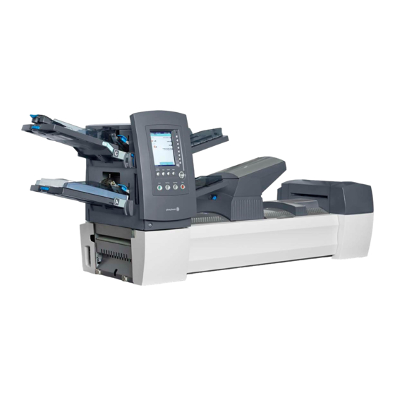
Relay 7000/8000 features an additional integrated High Capacity Envelope Feeder. Additional modules can be added to utilize the full potential of the system. Figure 2.1: The Relay 5000/6000 System Relay 7000/8000 only Feeder Tower Trays - feed sheets or inserts to the feeder tower. -
Page 22: System Components
2 • Meet the Inserting System System Manual Feeder - allows you to manually feed stapled or unstapled Components sets of up to 5 sheets of 20 lb (80gsm) paper. The machine waits for each set to be manually fed before folding and inserting the (continued) set automatically into the envelope. -
Page 23: Feeder Tower
Meet the Inserting System • 2 Feeder Tower The feeder tower is a two-sided tray holder/material feeder that stands at one end of the unit. Unlocking a latch on the left side of the tower opens it to expose feeder exit and tower transport rollers. This makes it easy to access media that may stop as it exits the tower. -
Page 24: Feeder Trays
2 • Meet the Inserting System Feeder Trays There are two types of feeder trays: • Sheet Trays • Insert Trays Required tray type is based on the type of material selected for a given job. Sheet Trays Sheet trays feed flat, unfolded material. Use only the recommended materials. -
Page 25: Insert Trays
Meet the Inserting System • 2 Insert Trays Insert trays feed items that do not need folding (envelopes, cards, booklets, slips and pre-folded media) into the system. Insert Trays have a weighted sliding mechanism known as a sled that keeps pressure on the material for proper feeding. -
Page 26: Manual Feeder
2 • Meet the Inserting System Manual Feeder Use the manual feeder to hand feed stapled or unstapled sets of up to five sheets. The machine waits for each set to be manually fed before folding and inserting the set into the envelope. NOTES: •... -
Page 27: Transport Deck
Meet the Inserting System • 2 Transport Deck The transport deck accepts material from the feeder lower and moves it through the various modules to produce a finished mail piece. The standard transport deck consists of the following: Moistener, Closer, Insertion Post-fold Pre-fold... -
Page 28: Folder
2 • Meet the Inserting System Folder The stack of collated sheets exits the Pre-fold Accumulator into the Folder. The folder then applies a fold to the stack and sends it to the Post-fold Accumulator. The Folder offers these options: •... -
Page 29: About The Control Panel
Meet the Inserting System • 2 About the The control panel consists of the following components: Control Panel • Screen Option Keys allow you to define settings for up to 24 jobs that you can store in the system’s memory. These keys also provide the means to edit any of the stored jobs. -
Page 30: Fixed Function Keys
2 • Meet the Inserting System Fixed Function The fixed function keys are the top row of keys under the screen. Each of these keys has an assigned function that is enabled or disabled based on Keys the screen that displays. Use of each of these keys is explained here: Reset Counters The system has two Reset Counters... -
Page 31: Fixed Function Keys (Continued)
Meet the Inserting System • 2 Fixed Function Resetting the Batch Counter Keys (continued) The batch counter counts up to a set number. It increments one count for each completed mail piece that the system detects. The system stops when it reaches the batch count. -
Page 32: Machine Action Keys
2 • Meet the Inserting System Machine Action The four keys along the bottom of the control panel are called machine action keys. Use these keys to run the system. Keys Trial Clear Start Stop Piece Deck Machine Action Keys Start Press this green-colored Start key to begin running the selected job. -
Page 33: Display Screen
Meet the Inserting System • 2 Display Screen The display screen is divided into two major areas: • Header area • Status area Home Job: ABC Header Area Run Trial Piece Low Sealant Job Items Select Another Job SwiftStart Menu Status Area Loading Instructions and Pre-Run Adjustments... -
Page 34: Status Area
2 • Meet the Inserting System Status Area The status area of the screen is devoted to displaying information about the task(s) you are performing. This area displays any or all of the following: • Mail Piece Icon Tree • Item Orientation •... -
Page 35: Status Area (Continued)
Meet the Inserting System • 2 Status Area • If any sheet feeder(s) are programmed to feed multiple sheets, a modified icon indicating multiple sheets will appear together with a (continued) number showing the number of sheets in the set. Number of sheets in set •... -
Page 36: Status Area (Continued)
2 • Meet the Inserting System Mail Piece Icon Tree Example Status Area Each icon displays important information about the mail piece component (continued) that it represents. The following explains information conveyed by the icon and how it assists you in loading and running a job. Window Envelope loaded flap down, flap last. - Page 37 Meet the Inserting System • 2 Status Area Item Orientation (continued) Use the screen navigation keys to highlight an icon in the Mail Piece Icon Tree to display information about the item that the icon represents. In most instances, an image appears in the status area of the screen and shows the required orientation for loading the item into the Tray.
- Page 38 2 • Meet the Inserting System Status Area Options (continued) The right side of the display screen lists the options that are available for the screen that currently displays. In some screens, options consist of other functions: in other screens options consist of different settings for a selected item in the screen.
-
Page 39: Access Rights
Meet the Inserting System • 2 Access Rights There are two security modes available on the system: • Login Not Required Mode - requires four-digit access code to perform supervisor and manager functions. • Login Required Mode - sets up access levels and requires a user ID and password for all system operator, supervisor, and manager functions. -
Page 40: Logging In
2 • Meet the Inserting System Access Rights When the Login Required Mode is enabled, entry of a user ID and password is needed to access the system. When Login Not Required (continued) Mode is enabled, entry of an access code is needed to access restricted functions. -
Page 41: About System Covers
Meet the Inserting System • 2 About System Three covers on the front side of the system, as shown here, open to provide access to paper release knobs. Covers Main Transport Deck Tower Base Cover Sealer Replacement Cover (open) (closed) Cover (closed) Figure 2.7.1: Front Covers Covers on the top of the transport deck open to provide access to the rollers... -
Page 42: Opening The Covers
2 • Meet the Inserting System Opening the The tower base cover interlocks with the main transport deck cover. This means that you cannot open the tower base cover unless you open the Covers main transport deck cover first. CAUTION Moving mechanism can result in personal injury. -
Page 43: About The Paper Release Knobs/Levers
Meet the Inserting System • 2 About the Paper There are ten paper release knobs and levers on the front side of the system. Each knob provides the means to turn rollers and move material out Release Knobs/ of the area in which it stalled. Each paper release lever opens an area of the Levers system and allows you to clear any material that may have stalled. - Page 44 This page is intentionally blank.
-
Page 45: Basic Operation
3 • Basic Operation Contents Connecting to Power ..............3-3 Powering Up ................3-3 Home Screen................3-4 Job Overview ................3-5 Selecting the Job .................3-6 Setting Up Feeders and Loading Materials .........3-7 Attaching Trays to the Feeder Tower ........3-7 Removing Trays from the Feeder Tower ....... 3-8 Loading the High Capacity Envelope Feeder (HCEF) .. - Page 46 This page is intentionally blank.
-
Page 47: Connecting To Power
Basic Operation • 3 Connecting to These instructions explain how to: Power • Properly power up the inserting system, and • Select a job. WARNING! Read the safety information in Chapter 1 before con- necting the system to power. To connect the system to power: 1. -
Page 48: Home Screen
3 • Basic Operation Home Screen When the system completes the startup process, the Home screen will display. The last job that was run displays on the Home screen. Information about the job displays along with the means to select a different job, edit settings for the displayed job, use the SwiftStart feature, and view loading ™... -
Page 49: Job Overview
Basic Operation • 3 Job Overview This chapter provides the instructions necessary to run, create, or edit a job. Running a Job - There are five major steps involved with running a job. These steps need to be followed in the order listed below: •... -
Page 50: Selecting The Job
3 • Basic Operation Selecting the If the job that you want to run is the one that currently displays in the Home screen, proceed to the Running a Trial Piece section of this chapter. Other- wise, follow the steps below to select the job: 1. -
Page 51: Setting Up Feeders And Loading Materials
Basic Operation • 3 Setting Up Once you select the job that you want to run, you need to set up the system to run it. This consists of doing the following: Feeders and • Attaching Trays to the Feeder Tower, if prompted. Loading •... -
Page 52: Removing Trays From The Feeder Tower
3 • Basic Operation 3. Slide the tray into the tray mounts until you feel the Tray seat into place. NOTE: The tray is seated properly when the notch on the bottom of each side of the tray is seated in the groove on each of the tray mounts. Notch on Tray Figure 3.1.2: Check Tray Seating Groove on... -
Page 53: Loading Material Into The Trays
Basic Operation • 3 Loading Material It is important to loosen (fan) any items in the stack that may be stuck together BEFORE you place the material in the tray. To do this: into the Trays 1. Hold one end of the stack in one hand. 2. - Page 54 3 • Basic Operation Adjusting Tray Side Guides Loading Material into the Trays A grooved, blue side guide adjustor is present at the open end of each tray. (continued) This adjustor controls the opening and closing functions of the tray's side guides.
- Page 55 Basic Operation • 3 Loading Material Loading a Sheet Tray into the Trays NOTE: To view a demo of the sheet tray loading and side guide adjustment (continued) processes: go to the Home screen and select “Loading Instructions and Pre-Run Adjustments”.
- Page 56 3 • Basic Operation Loading Material Loading Insert Trays into the Trays NOTE: To view a demo of the Insert Tray loading and side guide adjustment (continued) processes: go to the Home screen and select “Loading Instructions and Pre-Run Adjustments”. Use the UP/DOWN arrow keys to select an Insert in the Mail Piece Icon Tree, then select “Feeders Setup Demo”.
- Page 57 Basic Operation • 3 Loading Material Loading Insert Trays (continued) into the Trays 5. Finish loading the tray to the appropriate fill line for the insert type. (continued) 6. Tilt the material slightly toward the back of the tray. 7. While holding the material in the tilt position, gently pull up on the sled lock release to unlock it.
-
Page 58: Loading The High Capacity Envelope Feeder (Hcef)
3 • Basic Operation Loading the The HCEF holds up to 500 envelopes. Refer to Chapter 6, Reference for the envelope size ranges. High Capacity Envelope Feeder To load envelopes into the HCEF, you will need to adjust the side guides, wedge, and separator gap. - Page 59 Basic Operation • 3 Loading Adjusting the HCEF Wedge the HCEF 1. Insert an envelope into the HCEF with the bottom edge of the envelope (continued) against the center guide, in line with the two screws. The top edge of the envelope (edge with flap) should point towards the wedge.
- Page 60 3 • Basic Operation Loading the 4. Push down on the trail prop locking lever to lock the wedge into place HCEF (continued) and remove the envelope. Figure 3.7.2: Corner of Envelope in Center Slot 3-16 SV63136 Rev. A...
- Page 61 Basic Operation • 3 Loading Adjusting the HCEF Separator Gap the HCEF NOTE: You must adjust the HCEF Wedge before you can adjust the Separator (continued) Gap. Refer to Adjusting the HCEF Wedge in this chapter for more information. 1. Prepare an envelope for the separator gap adjustment: a.
- Page 62 3 • Basic Operation Loading 3. Place the envelope, bottom edge first, into the separator so the top the HCEF edge (flap crease) lines up with the (continued) edge of the tab on the Wedge. NOTE: The edge of the tab is indi- cated by two arrows.
-
Page 63: Making Pre-Run Adjustments
Basic Operation • 3 Making Pre-Run Once you have loaded the items for the selected job, you may need to make some envelope opener adjustments to ensure job accuracy. Adjustments Adjusting The envelope openers in the insertion area open each envelope to allow insertion of the contents. - Page 64 3 • Basic Operation Adjusting Perform Width Adjustments (Outer Envelope Openers) the Envelope 1. Loosen the thumbscrews on the top of the outer envelope openers. Openers (continued) Outer Envelope Opener Thumbscrews Figure 3.9.2: Outer Envelope Opener Locations 2. Slide the openers as required to align the pointers with the outer edges of the envelope.
- Page 65 Basic Operation • 3 Adjusting Perform Length Adjustments (Inner Envelope Openers) the Envelope 1. If using windowed envelopes, loosen the thumbscrews that secure each Openers inner envelope opener. (continued) NOTE: There are three inner envelope openers, that typically need length adjustments only.
- Page 66 3 • Basic Operation Adjusting the Envelope Openers (continued) Insertion Edges of Inner Envelope Openers Figure 3.9.5: Inner Envelope Openers Inserted into Envelope 4. Tighten the knob for the adjusted insertion edge. 5. Repeat steps #2 - 4 for the other two insertion edges. Verify Settings When you finish making the necessary envelope opener adjustments, close the insertion area cover, then verify your settings by doing the following:...
-
Page 67: Running A Trial Piece
Basic Operation • 3 Running a Trial Once the job setup is completed, you must run a trial piece to ensure sys- tem function and to verify the accuracy of your final mail piece. Follow these Piece steps to run a trial piece: 1. - Page 68 3 • Basic Operation Running a 5. Depending on your findings, choose one of the following options listed on the Trial Piece screen: Trial Piece a. If the trial mail piece passes inspection, select Trial Piece OK. You (continued) will be returned to the Home screen, or press START to begin the job.
-
Page 69: Reviewing The Job Settings
Basic Operation • 3 You may want to review the job settings before you start running the job. Reviewing the The Review Job screen provides an at-a-glance view of the settings for Job Settings each of the mail piece component parameters and the general job settings. This screen is a time efficient way to make sure that you have selected the correct job. -
Page 70: Starting The Job
3 • Basic Operation Starting the Job When your Trial Piece is verified, you are ready to start running the job. To do this: 1. Make sure that you are in the Home screen. 2. Press START. The system will begin running the job. SwiftStart ™... -
Page 71: Using Swiftstart
Basic Operation • 3 Using SwiftStart To use SwiftStart ™ ™ 1. Select SwiftStart from the Home screen. 2. Attach and load Feeder Trays: a. Load the outer envelopes in Insert Tray (A) or in the HCEF (G, if present on system). b. - Page 72 3 • Basic Operation Creating a Job • If the new job does not require scanning, select Normal Type to continue. (continued) • If the new job requires scanning, select Scanning Job. 4. The Create Outer Envelope screen displays. • If the job does not require an outer envelope, select No.
- Page 73 Basic Operation • 3 Creating a Job Menu Options Associated Options/Actions (continued) Sheet Follow the appropriate step below: • If this is the first sheet you are adding to the job and the Attached Printer is not present select the appropriate personalization option.
- Page 74 3 • Basic Operation Creating a Job Menu Options Associated Options/Actions (continued) Job Comments Use the alphanumeric matrix to enter any additional information related to the job. If the job will be saved by a supervisor or manager, you can make it easy for operators to identify/select the correct job in the future by entering a job description in the job comments area.
-
Page 75: Job Options
Basic Operation • 3 Job Options This section contains descriptions of the various options you can add or modify when creating or editing a job. Envelope Menu Item Associated Options and Actions Options Name Use the alphanumeric matrix to enter the envelope name. Size refers Toggle: specifically to the... - Page 76 3 • Basic Operation Envelope Menu Item Associated Options and Actions Options Additional Settings Double Detect allows the system sense when multiple envelopes (continued) are fed unintentionally. Note: This menu option is not available when the job re- quires a custom feeder. •...
-
Page 77: Fold Options
Basic Operation • 3 Envelope Menu Item Associated Options and Actions Options Additional Settings Envelope Select Feed allows you to indicate when the envelope (continued) (continued) should be used. Toggle: • Main • Alternate NOTE: This option is enabled only when the Scan feature is activated, two Outer Envelopes have been defined in a job and either one of the following: •... -
Page 78: Sheet Options
3 • Basic Operation Sheet Options Menu Item Associated Options and Actions Name Use the alphanumeric matrix to enter the job name. Control Document Read-Only field is the top sheet in • Yes, or the Mail Piece Icon • Tree. This field is read-only. - Page 79 Basic Operation • 3 Sheet Options Menu Item Associated Options and Actions (continued) Additional Settings. Double Detect allows the system to sense when multiple sheets are fed unintentionally. NOTE: This menu option is not available when the job requires a Custom Feeder.
- Page 80 3 • Basic Operation Sheet Options Menu Item Associated Options and Actions (continued) Additional Settings Scan Settings (continued) NOTE: The “Content in Line with Marks”, “Marks On”, “Marks on First Page Only”, and “Mark Location Settings” options are not available when the job requires a Custom Feeder. •...
-
Page 81: Insert Options
Basic Operation • 3 Insert Options Menu Item Associated Options and Actions Name Use the alphanumeric matrix to enter the job name. Insert Type includes • Reply Envelope - is also called a Business Reply Envelope. all items that do not •... - Page 82 3 • Basic Operation Insert Options Length is the • Auto measure - measures the recommended length (continued) dimension of the automatically. insert in the direction NOTE: Auto measure is not available when “Large Booklet” is of the feed. the selected insert or when the job requires a Custom Feeder. •...
- Page 83 Basic Operation • 3 Insert Options Menu Item Associated Options and Actions (continued) Additional Settings Double Detect allows the system sense when multiple inserts are fed unintentionally. NOTE: This menu option is not available when the job requires a Custom Feeder. •...
- Page 84 3 • Basic Operation Insert Options Menu Item Associated Options and Actions (continued) Additional Settings Scan Settings (continued) NOTE: The “Content in Line with Marks”, “Marks On”, “Marks on First Page Only”, and “Mark Location Settings” options are not available when the job requires a Custom Feeder. •...
-
Page 85: Editing A Job
Basic Operation • 3 Editing a Job Editing a job involves any or all of the following: • Changing characteristics for a selected item. • Adding an item to the mail piece. • Deleting an item from the mail piece. •... -
Page 86: Modifying Job Settings
3 • Basic Operation Modifying Job You can make changes to the job settings using the procedure described below. Settings 1. From the Home screen select Menu>Jobs>Edit Current Job. 2. Select Edit Job Settings. 3. The Job Comments screen displays. You can add Job Comments, toggle the Batch Mode on or off, make adjustments to the Batch Count and Set Over Max Count settings, or turn on the Use Postage Meter feature. -
Page 87: Adding An Item
Basic Operation • 3 Adding an Item You can add items to your mail piece one at a time using the procedure de- scribed below. To add an item to a mail piece: 1. From the Home screen select Menu>Jobs>Edit Current Job. The Edit Job screen displays. -
Page 88: Adding An Item (Continued)
3 • Basic Operation Adding an Item 6. If you selected Add Outer Envelope the Add Envelope screen displays. (continued) a. Use the screen option keys to define the new envelope parameters b. Select the desired item characteristics c. Press Accept when you are done. 7. -
Page 89: Moving An Item
Basic Operation • 3 Moving an Item To relocate a item within a mail piece collation order: 1. From the Home screen select Menu>Jobs>Edit Current Job. The Edit Job screen displays. 2. Use the UP/DOWN arrow keys to select the item. A highlight appears around the selected item. -
Page 90: Deleting An Item
3 • Basic Operation Deleting an Item To delete an item from the mail piece collation: 1. From the Home screen select Menu>Jobs>Edit Current Job. The Edit Job screen displays. 2. Use the UP/DOWN arrows to select the item to be deleted. A highlight will appear around the selected item. -
Page 91: Advanced Operation
4 • Advanced Operation Contents Overview..................4-3 Using the Alphanumeric Matrix ............4-3 Saving a Job ................4-4 Deleting a Job................4-5 Assigning User IDs and Passwords ..........4-6 Enabling and Disabling the High Capacity Sheet Feeder (HCSF) ........4-6 SV63136 Rev. A... - Page 92 This page is intentionally blank.
-
Page 93: Overview
Advanced Operation • 4 Overview This chapter explains use of the alphanumeric matrix and system use that exceeds the System Operator level of access. Functions explained in the chapter are: • Using the Alphanumeric Matrix • Saving a Job • Deleting a Job •... -
Page 94: Saving A Job
4 • Advanced Operation Saving a job requires supervisor or manager access rights. Saving a Job To Save a New Job: 1. Select Yes, Save from the Create – Save Created Job screen. (Refer to Creating a Job in Chapter 3 of this guide for more information.) NOTE: If you are not logged in with supervisor or manager access rights, you will be prompted to enter an access code. -
Page 95: Deleting A Job
Advanced Operation • 4 Deleting a Job Jobs that display in the Saved Jobs list are the only jobs that can be deleted. NOTE: Library jobs are permanent residents of the system's memory. The Delete function is disabled for the any of the Library jobs. To Delete a Job from the Saved Jobs List: 1. -
Page 96: Assigning User Ids And Passwords
4 • Advanced Operation Assigning You must have Manager level access rights to assign a user ID and pass- word. User IDs and 1. From the Home screen, select Menu>Tools. Passwords 2. Select Configure System>Security Level. NOTE: If you are not logged in with supervisor or manager access rights, you will be prompted to enter an access code. -
Page 97: Troubleshooting And Maintenance
5 • Troubleshooting and Maintenance Contents Adjusting Screen Brightness and Contrast ........5-3 Setting the Time and/or Date ............5-4 Changing the Language ..............5-5 Refilling the Sealing Solution ............5-6 Handling Material Stoppages ............5-6 Clearing a Stoppage .............. 5-6 Resuming the Job ..............5-7 Handling Outsorted Material .......... - Page 98 This page is intentionally blank.
-
Page 99: Adjusting Screen Brightness And Contrast
Troubleshooting • 5 Adjusting Follow the steps below to adjust the contrast and/or brightness of the dis- play screen: Screen 1. From the Home screen, select "Menu". Brightness and 2. From the Menu screen, select "Tools". Contrast 3. From the Tools screen, select "Configure System". 4. -
Page 100: Setting The Time And/Or Date
5 • Troubleshooting Setting the Time Follow the steps below to adjust the internal Time and/or Date of the sys- tem: and/or Date 1. From the Home screen, select "Menu". 2. From the Menu screen, select "Tools". 3. From the Tools screen, select "Configure System". 4. -
Page 101: Changing The Language
Troubleshooting • 5 Changing the Follow the steps below to change the language used on the display screen: Language 1. From the Home screen, select "Menu". 2. From the Menu screen, select "Change Language". 3. The Change Language screen displays the list of available languages. If necessary, use the "Next"... -
Page 102: Refilling The Sealing Solution
5 • Troubleshooting Refilling A warning message appears on the Display screen indicating that it is time to replenish sealing solution in the Sealer bottle : the Sealing To refill the bottle: Solution 1. Open the Sealer bottle cover and remove the bottle from its holder on the system and place it on a flat surface. -
Page 103: Resuming The Job
Troubleshooting • 5 Resuming the To resume running your job after a stoppage is cleared: 1. Make sure that there are no error messages on the screen and that all system covers are closed. 2. Press START. • If the error message on the screen instructed you to remove mate- rial in trays to start a new collation, pressing START will begin a new collation, otherwise •... -
Page 104: Troubleshooting Tables
5 • Troubleshooting Troubleshooting The system will generate an error message when a problem occurs. The message identifies the error and possibly the cause of it. Advice on fixing the Tables problem will also display. In addition to these messages, use the: •... - Page 105 Troubleshooting • 5 Table 5-3 Tower Feeder Problems Problem Cause Action Failure to feed. Material not within specifications. Check that all material meets published specifications. Refer to Feeder Tower Material Specifications in Chapter 6 of this guide for more information. •...
- Page 106 5 • Troubleshooting Table 5-3 Tower Feeder Problems (continued) Problem Cause Action System incorrectly detects Double detect is seeing flap or seam • Set the custom double detect window double feeds. of insert envelope where there is no flap, seam or window on the envelope.
- Page 107 Troubleshooting • 5 Table 5-4 Tower Area Problems Problem Cause Action Stoppage in tower area. Material not within Check that all material meets published specifications. specifications, causing skew. Refer to Feeder Tower Material Specifications in Chapter 6 of this guide for instructions. •...
- Page 108 5 • Troubleshooting Table 5-6 Insertion Area/Envelope Flapper Area Problems Problem Cause Action Stoppage in insertion area or Outer envelope is skewed. Check Side Guides; incorrect adjustment flapper area; failure to insert. can cause skewing. Refer to Adjusting Tray Side Guides in Chapter 3 of this guide for instructions.
- Page 109 Troubleshooting • 5 Table 5-6 Insertion Area/Envelope Flapper Area Problems Problem Cause Action Stoppage in Envelope openers improperly insertion area or adjusted. (continued). flapper area; failure to insert. (continued) Recommended distance: .5" .5-inch to 1 inch (15 to (15mm) 25mm) between the tip of the outside finger and the edge 1"...
- Page 110 5 • Troubleshooting Table 5-6 Insertion Area/Envelope Flapper Area Problems, continued Problem Cause Action • Contents of insertion Adjust the Aligner custom settings: pack are catching on NOTE: If the contents of the insertion pack are thick, and you side seam inside of are having trouble inserting the pack into a small envelope, be envelope.
- Page 111 Troubleshooting • 5 Table 5-7 Moistener/Mail Piece Exit Problems Problem Cause Action No seal, failure to seal, Sealing is off in job set up. • Check job definition. incomplete seals. • Make sure sealer is ON. Low sealant level. Add water or sealing solution. Poor quality envelopes.
- Page 112 5 • Troubleshooting Problem Cause Action Envelope exit through letter Collations may be too stiff If the envelope is longer than 6 inches (152mm), path is unreliable; envelope is to exit through the letter exit process it through the flat exit path: damaged.
- Page 113 Troubleshooting • 5 Table 5-9 Mail Piece Problems Problem Cause Action Wrong fold type. Job is set up incorrectly. Check job definition and make appropriate adjustments to meet job specifications. Fold panel length incorrect. Job is set up incorrectly. Select automeasure, or make manual adjustments to meet job specifications, then rerun Trial Piece.
-
Page 114: Routine Maintenance
5 • Troubleshooting Routine This section outlines the maintenance tasks you can perform on the system. Be sure to schedule routine service with your system supplier at the appro- Maintenance priate intervals. Daily Tasks • Remove any excess paper dust that has accumulated on or around the system modules. - Page 115 Troubleshooting • 5 Replacing the 3. Release the plastic latches (one on each side of the reservoir): Moistener Wick a. Place the thumb of one hand on the latch at rear of machine (i.e., the latch furthest from you) (continued) Figure 5.2: Releasing the Rear Latch b.
-
Page 116: Replacing The Moistener Brushes
5 • Troubleshooting 5. Wrap the paper towel around the old wick cartridge and discard. 6. Slide the new wick cartridge into the reservoir. Insert the cartridge with the open side of cartridge facing the exit end (rear) of machine. 7. - Page 117 Troubleshooting • 5 Replacing 2. Remove old brushes: the Moistener a. Hold the blue brush holder in place with one hand while you use the other hand to push the bristles of the old brush completely free from Brushes the holder. (continued) NOTE: You will be pushing the bristles toward yourself .
- Page 118 This page is intentionally blank. SV63136 Rev. A...
-
Page 119: 6• Specifications
6• Specifications Contents Overview..................6-3 System Specifications ..............6-3 Component Specifications ............6-5 Feeder Tower and Base Material Specifications ......6-7 General Information ............... 6-7 Outer Envelopes ..............6-7 Inserts .................. 6-10 Sheets ..................6-11 High Capacity Sheet Feeder (HCSF) Material Specifications............6-12 General Information ............. 6-12 Sheets ................. - Page 120 This page is intentionally blank. SV63136 Rev. A...
-
Page 121: Overview
All dimensions are approximate. Length overall, height Weight, unboxed 89" (2261 mm), 31" (787 mm) 327 lbs. (148 kg) Relay 5000 89" (2261 mm). 33.5" (851 mm) 350 lbs. (158 kg) Relay 8000 High Capacity Sheet 43.5" (1105 mm), 28.6" (726 mm) 150 lbs. - Page 122 (1537 mm) 118" LOA (2997 mm) NOTE: System depth is 22.8 in (579 mm). Drawings are not to scale. All dimensions approximate. The Relay 5000/6000 does not include the High Capacity Envelope Feeder. Figure 5.1: Elevation Views SV63136 Rev. A...
-
Page 123: Component Specifications
Specifications • 6 Component Capacities Specifications Tower Sheet/ • 350 20 lb. (80 gsm) sheets; 350 insert cards; 250 envelopes. Insert/Envelope • Feeders are multi-purpose: they can handle sheets, cards, slips Feeders and envelopes. • Feeders, including envelope feeders, can be linked to increase running time. - Page 124 *This Fold Type/Address Location/Envelope Type combination requires an inverter. High Capacity Envelope Feeder (HCEF) The HCEF is standard on the Relay 7000/8000 professional series; it is not available for Relay 5000/6000 series. Material Letter-size envelopes Depth: 3.5" (89 mm) to 6.5" (165 mm)
-
Page 125: Feeder Tower And Base Material Specifications
Specifications • 6 Feeder Tower For reliable operation, all materials must conform to published specifications. Feed problems and high stall rates are often due to use of and Base substandard materials. Material Specifications General Any material fed for letter-size mail pieces shall be capable of being Information transported through a 1.5 inch (38 mm) radius, 1/4 turn without permanent deformation, breaking of perforations, or any other damage to the piece. - Page 126 6 • Specifications Envelope Throat Definitions Outer Envelopes (continued) NOTE: Diagram is not drawn to scale. 5.3 in. (135 mm) Centered at Center Line 4 in. (100 mm) Centered at Center Line Dimension Value Description 1.6 inch (41 mm) Maximum throat depth measured at the center line of executive style envelopes. 1.4 inch (38 mm) Maximum throat depth measured at a distance of 5.3 inches (135 mm) centered at the center line.
- Page 127 Specifications • 6 Outer Envelopes Envelope Curl/Warp (continued) • An envelope placed flap up on a flat surface under its own weight shall have no corner raised more than 0.5 inch (13 mm) from the surface. • Curl/Warp of the envelope flap shall not exceed 1/8 inch (3 mm) measured while holding flap on flat surface at the crease line.
-
Page 128: Inserts
6 • Specifications Inserts Inserts are defined as material that does not require folding (may be pre- folded) before insertion into letter-sized envelopes. This definition includes individual sheets, collations of unfastened sheets, C folded or single folded inserts or pre-made, bound booklets (no fastener exposed that might damage rollers). -
Page 129: Sheets
Specifications • 6 Sheets Sheets refer to material that must be folded before being inserted into standard letter envelopes. In the special case of flats, sheets are not folded. A group of sheets is referred to as a collation. Material Substrates Acceptable paper types include new or recycled bond, text, laser and offset. -
Page 130: High Capacity Sheet Feeder (Hcsf) Material Specifications
6 • Specifications High Capacity For reliable operation, all materials must conform to published specifications. Feed problems and high stall rates are often due to use of substandard Sheet Feeder materials. (HCSF) Material Specifications General Any material fed for letter size mail pieces must be capable of being transported through a 1.5"... -
Page 131: Materials Not Certified For Use
Specifications • 6 HCSF - Sheet Specifications Parameter Minimum Value Maximum Value Width 7.99 inches (203 mm) 8.5 inches (216 mm) Length 9.15 inches (232mm) 11.69 inches (297 mm) Basic Weight 20 lb. (80 gsm) 24 lb. (90 gsm) NOTES: •... - Page 132 This page is intentionally blank.
-
Page 133: Add-On Modules
7 • Add-On Modules Contents About the Add-On Modules ............7-3 High Capacity Sheet Feeder (HCSF) ..........7-3 Loading the HCSF ..............7-4 Adjusting the HCSF Guides ........... 7-6 Flats Sealer .................7-8 Replacing the Envelope Edge Marker Roller ......7-9 File Based Processing ............7-10 Exit Options ................7-10 Connect+ MMI ..............7-11 Vertical Power Stacker ............ - Page 134 This page is intensionally blank.
-
Page 135: About The Add-On Modules
Add-On Modules • 7 About the Add- The system accepts several modules that enable it to maximize perfor- mance. Included in this list are: On Modules • High Capacity Sheet Feeder • Flats Sealer • Pre-folded Insert Feeder • Power Stacker High Capacity The HCSF add-on module attaches to the Feed Tower end of the system to provide greater upstream volume. -
Page 136: Loading The Hcsf
7 • Add-On Modules Loading the Each feeder in the HCSF holds up to 1000 sheets of 20 lb. (80 gsm) pa- per. Refer to Chapter 6 for recommended specifications on other types and HCSF weights of materials. To load sheets into the HCSF: 1. - Page 137 Add-On Modules • 7 Loading the HCSF Max fill line (continued) Figure 7.3: HCSF Loaded with Material 4. Load the remaining paper up to the fill line. 5. Repeat steps 2-5 for each remaining HCSF Tray. 6. Press the button on the front of the HCSF for each of the Trays. The loaded Tray(s) will move into position for feeding.
-
Page 138: Adjusting The Hcsf Guides
7 • Add-On Modules Adjusting the If the sheet width is different from the sheet width used in the previous job, you need to adjust the HCSF guides for the new job. HCSF Guides IMPORTANT: Make sure you have enabled the High Capacity Sheet Feeder Trays before performing this adjustment. - Page 139 Add-On Modules • 7 Adjusting the 5. Set the Length Guide: HCSF Guides a. Pull the length knob (knob 12) straight out. (continued) b. Turn the knob to position yellow line on the Length Guide Bar at the trailing end of the sheet. Yellow line on Length Guide Figure 7.7: Length Guide Bar...
-
Page 140: Flats Sealer
7 • Add-On Modules Flats Sealer The Flats Sealer add-on module attaches to the exit end of the base module to allow for the sealing of flat envelopes. The Flats Sealer can seal flat enve- lopes up to 0.25" (6.5 mm) in thickness. In the Moistener, Closer, Sealer module, brushes sweep across the flat envelope flap to wet the glued area of the flap. -
Page 141: Replacing The Envelope Edge Marker Roller
Add-On Modules • 7 The Flats Sealer also contains an envelope edge marker. The envelope edge marker will apply a mark at least 0.5" (12.5 mm) in length along the edge of the envelope facing the operator. You can use edge mark can be used to indicate tray breaks, ZIP breaks, every 50th envelope, high value checks, etc. -
Page 142: File Based Processing
7 • Add-On Modules File Based Mail stream integrity is the ability to ensure our clients deliver envelopes to their customers with only the intended enclosures. Processing The Relay system with file based processing software is a solution that pro- cesses mail with a high degree of mail run and mailpiece integrity. -
Page 143: Connect+ Mmi
Add-On Modules • 7 The Mail Machine Interface (MMI) enables communication between the Connect+ MMI inserter and the Connect+ mailing systems via a USB connection. The inserter sends start and stop signals to the mailing system, and the mailing system can send error messages back to the inserter to stop feeding. - Page 144 7 • Add-On Modules NOTE: Refer to the Operator Guide for you mailing system for more informa- tion about processing mail. 5. Adjust the side guide to the width of an envelope that will be used. See figures below for Connect+ requirements. NOTE: The MMI does not support flats.
- Page 145 Add-On Modules • 7 6. Verify the following: • There are sufficient funds for the job on the mailing system • The MMI is working; and • The correct mode is set on the mailing system. 7. Press the Start button on the inserting system. The inserting system begins to assemble pieces of mail, which the mail- ing system will then accept and process.
-
Page 146: Vertical Power Stacker
7 • Add-On Modules Vertical Power The Vertical Power Stacker is a compact, powered, bottom-feed stacker that connects to the output of several Pitney Bowes Document Inserting Stacker Systems, including the inserters. It neatly stacks the mail pieces fed Relay from the inserter and keeps them in the same order as they were originally loaded. - Page 147 8 • Scanning Contents Scanning Overview..............8-3 OMR ..................8-3 BCR ..................8-3 Physical Specifications for 2D Data Matrix Barcodes .... 8-6 Supported Square and Rectangular Formats ......8-6 Scanning Features ..............8-9 Supported ECC (Error Correction Code) Levels ....8-11 Setting Up a New Scan Configuration ........8-12 Setting Up an OMR Scan Configuration ......
- Page 148 This page is intentionally blank.
-
Page 149: Scanning • 8
Scanning • 8 The system offers two types of scanning; both types are optional features: Scanning • Optical Mark Recognition (OMR) Overview • Barcode Recognition (BCR) The purpose of OMR scanning is to ensure that a set of sheets that belongs together in a Mail Piece stays together as they make their way through the paper path and into the outer envelope. - Page 150 8 • Scanning BCR (continued) Direction of Feed: Example: "Picket" Orientation (BCR Marks ONLY) NOTE: A HCSF is required to scan barcodes in "picket" orientation. "Picket" ori- entation uses a moving beam scanner. Only one moving beam scanner is present on a single HCSF.
- Page 151 Scanning • 8 BCR (continued) The capacity of a Data Matrix barcode is determined primarily by two factors: • The dimension of the barcode measured by the number of modules. A module is either a black or white square. module •...
-
Page 152: Physical Specifications For 2D Data Matrix Barcodes
8 • Scanning Physical These are the Data Matrix Barcode physical dimensions that are supported by the HCSF. Specifications Dimensions for 2D Data Item Min. Max. Matrix Barcodes # of characters Symbol Width 3.3 mm (1/8") 15.875 mm (5/8") Symbol Length 3.3 mm (1/8") 19.05 mm (3/4") Module Size... - Page 153 Scanning • 8 Rectangular data matrix barcodes can be put on the page in several Supported orientations. Square and • Long edge of barcode in the direction of travel (short edge first): Rectangular Formats (continued) Example of Short Edge of Barcode in Travel Direction The following Rectangular Data Matrix formats shall be supported by the HCSF and the corresponding data capacity:...
- Page 154 8 • Scanning Supported • Short edge of barcode in the direction of travel (long edge first): Square and Rectangular Formats (continued) Example of Long Edge of Barcode in Travel Direction The following Rectangular Data Matrix formats shall be supported by the HCSF and the corresponding data capacity: Supported Rectangular Code Formats (Long Edge First) Size...
-
Page 155: Scanning Features
Scanning • 8 Scanning Dynamic Envelope Selection Dynamic envelope selection allows you to create scanning jobs on Relay Features 7000/8000 systems (with or without a High Capacity Sheet Feeder) that will insert mail piece contents into either letter-sized or flat envelopes. Letter-sized envelopes are loaded at the High Capacity Envelope Feeder. - Page 156 8 • Scanning Scanning Divert Sheet Functionality Divert sheet functionality allows you to create scanning jobs that will send Features sheets to the lower divert area if sets exceed a given sheet count or contain (continued) a specific scan mark. This feature is implemented in one of two ways •...
-
Page 157: Supported Ecc (Error Correction Code) Levels
Scanning • 8 Supported ECC Most Barcode readers do not require barcode internal data encoding to be specified in order to read the barcode. However, Data Matrix barcodes do (Error Correction support internal error detection and correction. The level of error detection Code) Levels and correction is known as the ECC level. -
Page 158: Setting Up A New Scan Configuration
8 • Scanning Setting Up When the job you are running includes scanning, you will need to: a New Scan • Have the BCR or OMR Scan Configuration Worksheet or some such listing of the required scan marks. Configuration • Enter the settings into the Configurations screen for each item included in the job's Scan Configuration. - Page 159 Scanning • 8 Setting Up an 8. The Add OMR Functions Selected Functions Available Functions OMR Scan screen displays. There are two lists available on the screen: Configuration • Selected Functions and (continued) Available Functions. • MC:2 Refer to BCR and OMR Mark PC:2 Levels in this section for a brief PN:2...
- Page 160 8 • Scanning Setting Up an Menu Option Associated Options/Actions OMR Scan Count Direction Allows you to specify the count direction. Configuration (Multi-bit only) • Up (default), (continued) • Down, or • Random (MC only). When Up is selected, the relevant code’s binary value will increase as the system scans each page.
-
Page 161: Setting Up A Bcr Scan Configuration
Scanning • 8 Setting Up an Menu Option Associated Options/Actions OMR Scan Allows you to specify the least significant bit. Configuration Toggles: (continued) • Last (default, farthest from top of page), or • First. When First is selected for the Least Significant Bit option, the least significant bit is closest to the top of the page. - Page 162 8 • Scanning Setting Up 6. The Create Scan Code screen appears. Enter the character, bit a BCR Scan and size information on the "BCR Configuration Scan Configuration Worksheet" for a (continued) function. Refer to BCR and OMR Mark Levels in this chapter for a brief description of the function of each mark.
- Page 163 Scanning • 8 Setting Up Menu Option Associated Options/Actions a BCR Scan Count Direction Allows you to specify the count direction. Configuration • Up (default), (continued) • Down, or • Random (MC only). When Up is selected, the relevant code’s binary value will increase as the system scans each page.
- Page 164 8 • Scanning Setting Up Menu Option Associated Options/Actions a BCR Scan Wrap At Displays “Wrap At” numeric entry screen, where you enter Configuration the maximum code value in decimal format. (continued) • If the count direction is Up, the next code after this value will be 0 or 1, depending on the Includes Zero setting.
-
Page 165: Editing A Scan Configuration
Scanning • 8 Editing a Scan Editing an OMR Scan Configuration Configuration To edit an OMR Scan Configuration: 1. From the Home screen, select Menu>Tools. 2. Select Configure System>Scan Configuration Setup. NOTE: If you are not logged in with supervisor or manager access rights, you will be prompted to enter an access code. -
Page 166: Editing A Bcr Scan Configuration
8 • Scanning Editing a To edit a BCR Scan Configuration: BCR Scan 1. From the Home screen, select Menu>Tools. Configuration 2. Select Configure System>Scan Configuration Setup. NOTE: If you are not logged in with supervisor or manager access rights, you will be prompted to enter an access code. -
Page 167: Copying A Scan Configuration
Scanning • 8 Copying a Scan You can save a copy of a selected scan configuration under a new name. This feature permanently saves the current scan configuration setup as a Configuration new scan configuration with a different name. NOTES: •... -
Page 168: Reviewing A Scan Configuration
8 • Scanning Reviewing If necessary, you can view a list of marks associated with the Scan Configu- ration without entering the Edit mode. a Scan Configuration NOTE: This option is only available if the PC Control is set to No. 1. -
Page 169: Assigning A Scan Configuration To An Existing Job
Scanning • 8 Assigning Follow the steps in this section to assign a scan configuration to an existing job (either the current job, or another job) that has been created previously. a Scan 1. From the Home screen, select Menu>Jobs then select: Configuration •... - Page 170 8 • Scanning Assigning Menu Option Associated Options/Actions a Scan Mark Location Allows you to setup various OMR mark-related Configuration Settings measurements: to an Existing NOTE: This option is • Top of Page to First Mark is the distance from the top of disabled when Content the page to the first mark.
-
Page 171: Adjusting The Scan Heads
Scanning • 8 Assigning 11. Once the scan settings have been entered, select Accept to return to settings screen for the sheet or insert. a Scan 12. Select Select Feed Setting and choose the appropriate feeder setting Configuration for the item (none, SF1, SF2, SF3, SF4, SF5, SF6, SF7, SF8 or SF9). to an Existing 13. - Page 172 8 • Scanning Adjusting the 3. Fold the sheet horizontally, so the barcode appears on either side of the Scan Heads fold line. for Ladder or 4. Open the main transport deck cover. 2D Orientation Use the ruler to measure the distance Marks (continued) from the center of the sheet (lined up at 0 on the ruler) to the center of the...
- Page 173 Scanning • 8 Adjusting the 8. Use the blue thumbwheel to move the scan head. Move the thumbwheel until the pointer lines up with the measurement (distance from the center Scan Heads of the page to the center of the mark) defined earlier. for Ladder or 2D Orientation Blue thumbwheel...
-
Page 174: Adjusting The Scan Heads For Picket Orientation Marks
8 • Scanning Adjusting the To adjust the scan heads: Scan Heads 1. Fold one of the sheets to be scanned in half vertically (side with mark facing for Picket up.) Orientation 2. Draw two arrows, one at the top of the Marks mark, and one at the bottom of the mark, pointing towards the top of the... - Page 175 Scanning • 8 Adjusting the 7. Determine the direction the Scan Head needs to be moved (to the left or right of 0 on the ruler): Scan Heads • Make sure the center of the sheet (the vertical fold) is lined up with for Picket the at the center of the machine (at 0 on the ruler.) Orientation...
-
Page 176: Omr Specifications
8 • Scanning • For best line discrimination, maintain a 5 to 1 light to dark space ratio. This means the spacing between lines must be at least 6 times the width Specifications of and limits the maximum allowable line thickness to .635 mm (0.025”). •... -
Page 177: Omr Placement Specifications For Feeder Tower
Scanning • 8 OMR Print and OMR Placement Specifications for Feeder Tower (Ladder Orientation) Placement Specifications Clear Zone Diagram is not to scale 9 mm Leading Edge min. 11 mm min. Feeder Tower: 20 mm min. to clear zone (dotted line), 20 mm min. -
Page 178: Omr Placement Specifications For Hcsf (New Scan Kit F790250 - Ladder Orientation)
8 • Scanning OMR Print and OMR Placement Specifications for HCSF (New Scan Kit F790250 - Ladder Orientation) Placement Specifications Clear Zone Diagram is not to scale 9 mm Leading Edge min. 11 mm min. to clear zone (dotted line), 20 mm min. -
Page 179: Barcode Specifications
Scanning • 8 Barcode • Code 39 and Interleaved 2 of 5 (I 2 of 5) are supported. Extended Code 39 is not permitted. Barcode symbologies without start and stop Specifications characters and internal integrity features such as I 2 of 5 should use a checksum byte. -
Page 180: Barcode Print And Placement Specifications
8 • Scanning Barcode Print 1D Barcode Placement Specifications for Feeder Tower and Placement (Ladder Orientation) Specifications Clear Zone Diagram is not to scale 3 mm min. Leading Edge 17 mm min. Feeder Tower: 20 mm min. to clear zone (dotted line), 20 mm min. -
Page 181: Barcode Print And Placement Specifications
Scanning • 8 Barcode Print 1D Barcode Placement Specifications for HCSF and Placement (New Scan Kit F790250 - Ladder Orientation) Specifications Clear Zone Diagram is not to scale 3 mm min. Leading Edge 17 mm min. to clear zone (dotted line), 20 mm min. -
Page 182: Barcode Print And Placement Specifications
8 • Scanning Barcode Print 1D Barcode Print and Placement Specifications for HCSF and Placement (Original Scan Kit F790050 - Picket Fence Orientation) Specifications Clear Zone Diagram is not to scale 3 mm Leading Edge min. 17 mm min. *12345* HCSF: 32 mm min. -
Page 183: Barcode Print And Placement Specifications
Scanning • 8 Barcode Print 1D Barcode Placement Specifications for HCSF and Placement (New Scan Kit F790250 - Picket Fence Orientation) Specifications Clear Zone Diagram is not to scale 3 mm Leading Edge min. 17 mm min. *12345* to clear zone (dot- ted line), 3 mm... -
Page 184: Barcode Print And Placement Specifications
8 • Scanning Barcode Print 2D Barcode Placement Specifications for HCSF and Placement (New Scan Kit F790250 - Horizontal/Vertical Orientation) Specifications Clear Zone Diagram is not to scale 6 mm Leading Edge min. 6 mm 6 mm min. min. 6 mm min. -
Page 185: Setting The Omr Scanning Area
Scanning • 8 Setting the Material is scanned as it feeds through the machine. This means that the scanner reads a vertical strip or margin down the page, defined by the OMR Scanning specifications. Area The system must be told if the entire margin (the strip down the page that is scanned for marks) is clear of any other printing or punched holes, etc. -
Page 186: Defining The Clear Zone
8 • Scanning Defining the 1. When requested by the machine, measure and enter the distance (A) from the top edge of the sheet to the point after the printed matter where Clear Zone you wish the machine to START scanning. 2. -
Page 187: Additional Information
Scanning • 8 Additional • Paper weight range for OMR is 18 lb. (70 gsm) to 32 lb. (120 gsm). • Feeder linking will only work correctly if the operator has started with the Information correct sheet (i.e. linking can only be done reliably on a collation break). The feed order and print order will determine if feeder linking is possible. -
Page 188: Basic Level
8 • Scanning Basic Level The Basic Level of scanning contains marks that control and check for er- rors within a collation. The following marks perform basic control functions indicating the beginning, end, and how to control a collation. Mark Purpose BOC - Beginning of This mark indicates that it is the first sheet to be fed within a... - Page 189 Scanning • 8 Basic Level The following marks set up a readable code and provide basic collation integrity. (continued) Mark Purpose BM - Benchmark This is a mandatory mark within multi-mark OMR codes (OMR Only) to indicate the starting point of the code. It verifies that the scanner is working properly, and it helps detect printing problems.
-
Page 190: Enhanced Integrity Level
8 • Scanning Basic Level The following marks allow the system to read legacy or competitive OMR codes. (continued) Mark Purpose This mark allows the system to ignore marks it does not IGN(n) - Ignore support. (OMR Only) TM - Timing This mark is needed by some machines to read OMR (OMR Only) marks correctly. - Page 191 Scanning • 8 Enhanced SQ (Select Quantity): Allows the user, with dedicated scan marks on the control document, to have more than one insert fed from a specific Integrity Level tray from the Tower. This features works as a Page Count (continued) scan mark without the Insert being controlling.
-
Page 192: Selective Operations Level
8 • Scanning Selective The Selective Operations level of scanning contains marks that provide special feeding instructions. Operations Level Mark Purpose DVS - Divert Sheets When present, this mark indicates that the accumulation in the pre-fold accumulator should be diverted into the divert bin without folding or completing assembly. - Page 193 Appendix A • Glossary Contents Basic Terms ................A-3 Material References .............. A-3 Machine Functions ..............A-4 Icon Glossary................A-5 Envelope Icons ..............A-5 Fold Icons ................A-6 Sheet Icons ................A-6 Insert Icons ................A-7 Feeder Assignment Icons ............A-8 Other Icons ................
- Page 194 This page is intentionally blank.
-
Page 195: Basic Terms
Glossary • A Basic Terms The following table lists and defines standard terms used in the system's screens and this Operator Guide. Material References Additional Sheet - Additional sheet(s) can be added to the Mail Piece. Each will be placed into the envelope behind the Control Document. Control Document - This sheet normally contains the destination address. -
Page 196: Machine Functions
A • Glossary Basic Terms Sheet - A single piece of paper that will require folding by the machine be- fore it is placed into an envelope. In the Mail Piece Icon Tree, the sheet icon (continued) represents a stack of single sheets, or a stack of pre-collated sets of sheets. Shingle - The method of loading inserts into a Feeder in a partially over- lapped manner, like tiles on a roof. -
Page 197: Icon Glossary
Glossary • A The tables in this section provide descriptions of the various icons you will Icon Glossary see on the display screen. Dark lines within an icon represent features Light grey lines you can plainly see. within an icon represent features that you cannot be see. -
Page 198: Fold Icons
A • Glossary Icon Glossary Fold Icons (continued) No Fold C Fold Z Fold Single Fold Double Fold Sheet Icons Orientation: Orientation: Orientation: Orientation: face up, top face up, bottom face down, top face down, first. first. first. bottom first. Sheet, Not Personalized Sheet, Top... -
Page 199: Icon Glossary
Glossary • A Icon Glossary Insert Icons (continued) Orientation: Orientation: Orientation: Orientation: face up, top face up, face down, top face down, first. bottom first. first. bottom first. Slip or Generic Insert Reply Envelope Reply Card Multiple Slips or Generic Inserts Multiple Reply Envelopes Multiple Reply Cards... -
Page 200: Feeder Assignment Icons
A • Glossary Icon Glossary Feeder Assignment Icons (continued) Feeder assignment is indicated by a letter in a grey square to the right of the job item icon in the Mail Piece Icon Tree. The letter that appears in the blue square will vary, depending upon the assigned feeder. - Page 202 3001 Summer Street Stamford, CT 06926-0700 www.pitneybowes.com SV63136 Rev. A © 2015 Pitney Bowes Inc. All Rights Reserved...