Table of Contents
Advertisement
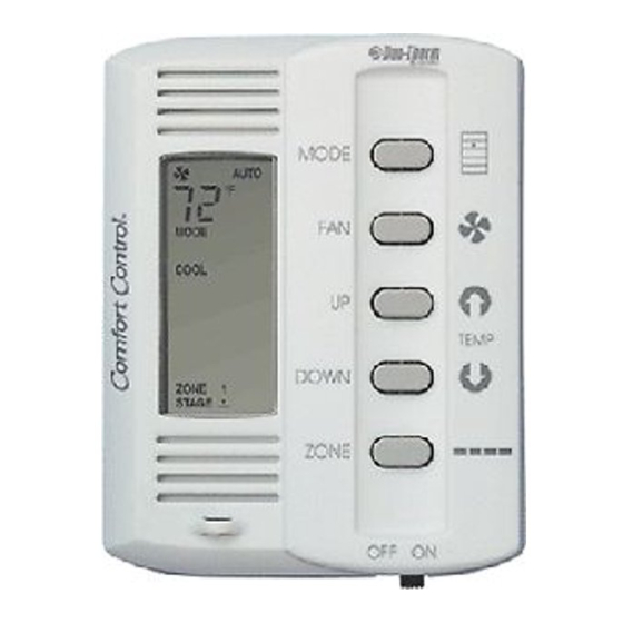
TROUBLESHOOTING
5 BUTTON 3109228.001
COMFORT CONTROL
CENTER SYSTEM
INTRODUCTION
The Comfort Control Center control system can be used to
operate the following Duo-Therm Units:
Basement Air Conditioners
Basement Heat Pumps
Dual Basement Air Conditioners
Dual Basement Heat Pumps
Other Manufacturer's Furnaces
A majority of air conditioner and heat pump problems are
electrical and can be found very easily.
To find a problem in the electrical system, you need to be
able to diagnose the following:
TOOLS REQUIRED
The air conditioner can be checked with a voltmeter, ohm-
meter, clamp-on ammeters and two good thermometers.
Some clamp-on ammeters can read voltage and ohms.
FIG. 1
Form No. 3307835.003 1/02
(French 3307836.001)
©2002 Dometic Corporation
LaGrange, IN 46761
for the
10. PTCR Device
AIR CONDITIONER
BULLETIN A29/2A
JANUARY 2002
A.
QUICK-CHECK TROUBLE-
SHOOTING FOR COMFORT
CONTROL CENTER (CCC)
CONTROLS
For detailed troubleshooting, refer to sec-
tion noted.
1. Air Conditioner/Heat Pump turned on –
No display
a. Reset - Sec. B15
b. DC Voltage - Sec. B17
c. Cable Assembly - Sec. B2
d. AC Control Module - Sec. B8
e. Comfort Control Center (CCC) - Sec. B15
2. Air Conditioner/Heat Pump turned on –
Has display, improper operation
a. Power Source - Sec. B1
b. Reset - Sec. B16
c. Configuration - Sec. B14
d. Wiring - Sec. B7
e. AC Control Module - Sec. B8
f. Comfort Control Center (CCC) - Sec. B15
3. Air Conditioner/Heat Pump turned on –
Fan runs, No compressor operation
a. Start Relay/PTCR - Sec. B10
b. Start Capacitor - Sec. B5
c. Fan/Run Capacitor - Sec. B4
d. Cold Control - AC Only, Sec. B12
e. Outdoor Ambient Sensor (HP) - Sec. B13
f. Compressor - Sec. B3
g. Wiring - Sec. B7
h. Comfort Control Center - Sec. B15
i. AC Control Module - Sec. B8
4. Air Conditioner/Heat Pump turned on – Com-
pressor runs, No fan operation
a. Fan/Run Capacitor - Sec. B4
b. Motor - Sec. B5
c. Wiring - Sec. B7
d. Comfort Control Center (CCC) - Sec. B15
e. AC Control Module - Sec. B8
5. Heat Pump turned on – Compressor runs and
fan runs, No heat output
a. Reversing Valve - Sec. B9
b. Wiring - Sec. B7
c. AC Control Module - Sec. B8
1
Advertisement
Table of Contents
Troubleshooting

Related Manuals for Dometic 3109228.001


Summary of Contents for Dometic 3109228.001
-
Page 1: Troubleshooting
TROUBLESHOOTING for the AIR CONDITIONER 5 BUTTON 3109228.001 BULLETIN A29/2A COMFORT CONTROL JANUARY 2002 CENTER SYSTEM INTRODUCTION QUICK-CHECK TROUBLE- The Comfort Control Center control system can be used to SHOOTING FOR COMFORT operate the following Duo-Therm Units: CONTROL CENTER (CCC) - Page 2 B. DETAILED TROUBLESHOOTING FOR COMFORT CONTROL For normal operation of the unit, AC voltage CENTER (CCC) CONTROLS must stay between 103.5 VAC and 126.5 VAC. Operation of the unit outside of this voltage We will now start electrically troubleshooting Comfort Con- trol Center (CCC) controlled units.
- Page 3 The cable should be made in the following manner: units the compressor run and fan/blower capacitor are in the same case. Cut the control cable to the desired length. When cutting make sure ends are cut straight, not diagonally. Next, use The compressor run and fan/blower capacitor are housed in an RJ-11 connector crimping tool.
- Page 4 The proper location of the remote sensor is very important If the circuit is competed to a particular component to maintain a comfortable temperature in the RV. The fol- and that component will not operate, the problem is lowing rules should be observed when selecting a location: in the roof top unit.
- Page 5 Use an AC light bulb to test if the relays on the board cold line in the cooling mode, the direction of flow is not are completing a circuit. Check from the common correct. (white wire) to: Check the solenoid coil for ohms continuity. An open cir- “NO”...
- Page 6 12.COLD CONTROL 13.AMBIENT SENSOR (Low Temperature Protection Device) The ambient sensor is the outside air temperature sensor The cold (freeze) control is used on both air conditioners and used on heat pumps only. This device allows the heat and heat pumps. When the temperature of the coil reaches pump to operate down to 30 the freezing point the compressor will stop operation and To check the ambient sensor, first measure the outside...
- Page 7 14.CONFIGURATION If a furnace is operated by the Comfort Control Center, the The Comfort Control Center configuration relates to setting thermostat wires are attached to the two (2) blue wires from the dip switches and particular components (remote sen- the control box. The furnace dip switch for that zone (con- sor, cold control, furnace, ambient sensor and load man- trol box or power module) is turned on.
- Page 8 16. SYSTEM RESET a. Turn the ON/OFF switch to “OFF” position. b. Simultaneously depress and hold the MODE and ZONE push-buttons while turning the ON/OFF switch to “ON”. FF should appear in the LCD display until the MODE and ZONE push-buttons are released. c.
- Page 9 This Manual is Compliments of Northwest RV Supply 86325 College View Road Eugene, OR 97405 Local: 541-746-9092 Toll-Free: 866-678-7467 Fax: 541-736-5573 http://www.nwrvsupply.com mail@nwrvsupply.com Northwest RV Supply carries a large spectrum of surplus, used, and new RV parts and components. Please feel free to visit our website for additional information.