Advertisement
Quick Links
LIMITED FIVE-YEAR WARRANTY
If within one (5) years from the date of purchase, this product fails due to a defect in material or workmanship, Intermatic Incorporated will repair
or replace it, at its sole option, free of charge. This warranty is extended to the original household purchaser only and is not transferable. This war-
ranty does not apply to: (a) damage to units caused by accident, dropping or abuse in handling, acts of God or any negligent use; (b) units which
have been subject to unauthorized repair, opened, taken apart or otherwise modified; (c) units not used in accordance with instructions; (d) dam-
ages exceeding the cost of the product; (e) sealed lamps and/or lamp bulbs, LED's and batteries; (f) the finish on any portion of the product, such as
surface and/or weathering, as this is considered normal wear and tear; (g) transit damage, initial installation costs, removal costs, or reinstallation
costs.
INTERMATIC INCORPORATED WILL NOT BE LIABLE FOR INCIDENTAL OR CONSEQUENTIAL DAMAGES. SOME STATES DO NOT ALLOW THE
EXCLUSION OR LIMITATION OF INCIDENTAL OR CONSEQUENTIAL DAMAGES, SO THE ABOVE LIMITATION OR EXCLUSION MAY NOT APPLY TO
YOU. THIS WARRANTY IS IN LIEU OF ALL OTHER EXPRESS OR IMPLIED WARRANTIES. ALL IMPLIED WARRANTIES, INCLUDING THE WARRANTY
OF MERCHANTABILITY AND THE WARRANTY OF FITNESS FOR A PARTICULAR PURPOSE, ARE HEREBY MODIFIED TO EXIST ONLY AS CON-
TAINED IN THIS LIMITED WARRANTY, AND SHALL BE OF THE SAME DURATION AS THE WARRANTY PERIOD STATED ABOVE. SOME STATES DO
NOT ALLOW LIMITATIONS ON THE DURATION OF AN IMPLIED WARRANTY, SO THE ABOVE LIMITATION MAY NOT APPLY TO YOU.
This warranty service is available by either (a) returning the product to the dealer from whom the unit was purchased, or (b) mailing the product,
along with proof of purchase, postage prepaid to the authorized service center listed below. This warranty is made by: Intermatic Incorporated/
After Sales Service/7777 Winn Rd., Spring Grove, Illinois 60081-9698/815-675-7000 http://www.intermatic.com Please be sure to wrap the product
securely to avoid shipping damage.
INTERMATIC, INC., SPRING GROVE, IL 60081-9698
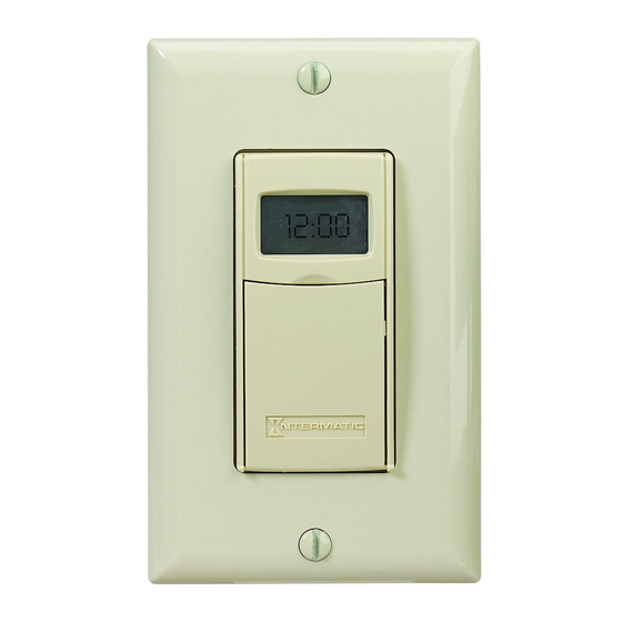
MODEL EI400 Series
Installation and User Instructions
Ratings
•
Resistive (
heater) 20 Amp, 120-277 VAC
•
Tungsten (
incandescent) 15 Amp @ 120 VAC, 6 Amp @ 208-277 VAC
fluorescent) 16 Amp @ 120-277 VAC
•
Ballast (
•
Motors 1 H.P. @ 120 VAC, 2 H.P. @ 240 VAC
•
DC Loads 4 Amp @ 12 VDC, 2 Amp @ 28 VDC
WARNING
•
Electrical shock hazard. Risk of injury or death. Remove electrical power
at service panel before installing.
•
Risk of fire and burns. Do not recharge, disassemble, heat above 100° C,
crush, or incinerate the lithium battery. Keep battery out of reach of
children. Replace only with Panasonic Type CR2 or equivalent CR2 battery
approved by Underwriters Laboratories (UL). Use of other battery may pres-
ent risk of fire or explosion upon disposal of the battery.
•
Risk of fire. Do not use timer to control devices that could have dangerous
consequences due to inaccurate timing, such as sun lamps, sauna, heat-
ers, crock pots, etc.
NOTICE
•
Follow local electrical codes during installation.
•
Risk of timer damage due to leakage if weak battery is not replaced promptly.
•
Dispose of used battery promptly per local regulations.
1 – Before Installing, Check the Battery
Before installing the shut-off timer into the wall, make sure the sup-
plied battery is installed and working, and the device has been reset.
1.
Open the access door to reveal the battery tray, located below
the ON/OFF keypad.
2.
If there is a pull tab at the battery tray, remove the tab to connect
the installed battery. Make sure battery tray is pushed fully into
place. Proceed to Step 6.
3.
If the battery was supplied loose, use a flat screwdriver to pry
loose the battery tray.
4.
Place the supplied "CR2" battery into the tray, observing
markings on tray.
5.
Replace the battery tray into the timer.
6.
The display will initialize itself then display "OFF" with the dark
light bulb icon. The timer will "beep".
7.
Press the
ON/OFF button. The shut-off timer should "click."
NOTE: There is an intentional 1-second delay, after pressing
the ON/OFF button, before the timer clicks OFF.
8.
If the display is blank, the battery may be dead. Replace the bat-
tery before installing the timer.
2 – Before Installing, Reset the Timer
Before installing, reset the timer to clear out any settings.
1.
ON/OFF.
Hold down
2.
Using a pen or paper clip, press and release the
which is the small round button to the lower right of the + button.
The display will initialize itself and the timer will "beep".
3.
When the screen displays "INIT", release the
timer will display "OFF" with the dark light bulb icon.
3 – Install the Timer into the Wall
1.
Turn off power at the service panel by REMOVING FUSE or
TURNING THE CIRCUIT BREAKER OFF.
2.
Remove the existing wall switch.
3.
158EI12562
Trim building wires to 7/16" as shown.
Digital Auto Shut-Off
If a Single Switch Setup:
a.
Connect one of the two wires from
the wall to the black wire from the
timer, using the twist connectors
provided.
b.
Connect the other wire from the
wall to the blue wire from the
timer, using the twist connectors
provided.
NOTE: The RED wire is not used
in single-switch installations. Cap with a twist connector.
c.
Connect the GREEN wire to the grounding screw in the box. If a
plastic box, connect to ground as supplied.
d.
Make sure all twist connectors are tight.
If a 3-Way Switch Setup:
NOTE: The distance between
timer and remote switch must not
exceed 100 feet.
a.
Locate the COMMON wire
connected to first old switch.
It might be attached to a dif-
ferent colored screw, or find markings on old switch.
b.
Connect BLACK wire from timer to COMMON wire, using a twist
connector.
c.
Connect the other two wires from the old switch as follows: one
to the BLUE wire and the other to the RED wire from the timer.
d.
Connect the GREEN wire to the grounding screw in the box. If a
plastic box, connect to ground as supplied.
e.
Using diagram #1 below. Identify and remove wire "C" from the
"Common" terminal of your existing remote switch.
DIAGRAM 1:
"COMMON" TERMINAL
TYPICAL
LINE
EXISTING
2-SWITCH
3-WAY
SETUP
MAIN SWITCH
f.
Using diagram # 2 below, remove and reconnect wires "B" and
"C" to the "Common" terminal of your remote switch, using a
+ and –
jumper wire, if necessary. Follow diagram # 3 below, if using a
new single-pole remote switch.
DIAGRAM 2:
2-SWITCH SETUP,
LINE
BLACK
TIMER INSTALL
TIMER
RE-USING EXISTING
REMOTE 3-WAY SWITCH
DIAGRAM 3:
LINE
2-SWITCH SETUP,
BLACK
TIMER INSTALL USING
NEW SINGLE-POLE
REMOTE SWITCH
NOTE: For new construction or to replace a dimmer switch,
RESET button,
a lighted switch, or a 3-way switch without screw terminals, a
single-pole switch can be used at the remote location, as shown.
NOTE: If the building's wiring colors don't allow you to tell wire
ON/OFF button. The
"A" from "B," just pick one of the two wires and connect as if it is
wire "B." After the installation is complete, if the controlled light
or device will not turn on properly, simply reverse wires "A" and
"B." See Steps J and K for how to check.
g.
Tuck wires into the timer wall box leaving room for the timer.
h.
Using screws provided, mount the timer into the wall box, then
7/16"
install the wall plate.
Timer
BLACK WIRE
BLUE WIRE
RED WIRE
(capped, not connected)
RED WIRE
BLUE WIRE
WIRE FROM
"COMMON" OF
OLD SWITCH
BLACK WIRE
LOAD
WIRE "A"
WIRE "C"
NEUTRAL
WIRE "B"
3-WAY
REMOTE SWITCH
LOAD
NEUTRAL
BLUE
WIRE "B"
WIRE "C"
JUMPER
RED
WIRE "A"
"COMMON" TERMINAL
3-WAY
NOT USED
REMOTE SWITCH
LOAD
NEUTRAL
BLUE
WIRE "B"
WIRE "C"
TIMER
JUMPER
RED
WIRE "A"
SINGLE-POLE
REMOTE SWITCH
Advertisement

Related Manuals for Intermatic EI400 Series


Summary of Contents for Intermatic EI400 Series
- Page 1 If the display is blank, the battery may be dead. Replace the bat- LOAD If within one (5) years from the date of purchase, this product fails due to a defect in material or workmanship, Intermatic Incorporated will repair DIAGRAM 3: tery before installing the timer.
-
Page 2: Troubleshooting Guide
— either OFF or ON. also powered OFF. NOTE: When the timer begins its next cycle, the countdown Multi-switch applications using the EI400 Series timer are wired 5 – Set the Timer will return to the programmed setting.