Table of Contents
Advertisement
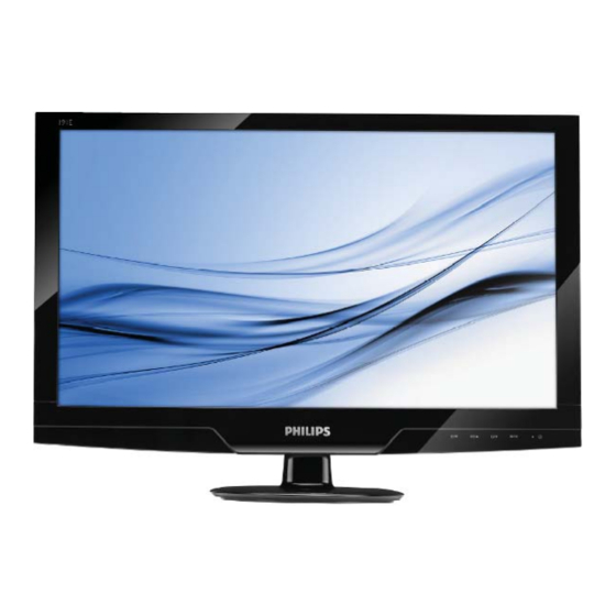
18.5 LCD Color Monitor
191E2SB/00
Service
191E2SB/10
Service
191E2SB/27
Service
191E2SB/62
191E2SB/69
191E2SB/71
191E2SB/73
191E2SB/75
191E2SB/93
191E2SB/94
Table of Contents......................................................1
Revision List.............................................................2
Important Safety Notice............................................3
1. Monitor Specifications............................................4
2. LCD Monitor Description........................................7
3. Operation Instructions..........................................9
3.1General Instructions.....................................9
3.2 Control Buttons...........................................9
3.3 OSD Menu......................................................10
4. Input/output Specification....................................11
4.1 Input Signal Connector......................................11
4.2 Resolution & Preset Modes.................................12
4.3 Pixel Defect Policy.......................................13
4. 4 Failure Mode of Panel.................................15
5. Block Diagram..............................................16
5.1 Scaler Board.....................................................16
5.2 Power Board.................................................18
6. Schematic Diagram.............................................. 19
6.1 Scaler Board..............................................28
6.2 Adapter Board....................................................28
ANY PERSON ATTEMPTING TO SERVICE THIS CHASSIS MUST FAMILIARIZE HIMSELF WITH THE
CHASSIS AND BE AWARE OF THE NECESSARY SAFETY PRECAUTIONS TO BE USED WHEN
SERVICING ELECTRONIC EQUIPMENT CONTAINING HIGH VOLTAGES.
CAUTION: USE A SEPARATE ISOLATION TRANSFOMER FOR THIS UNIT WHEN SERVICING
REFER TO BACK COVER FOR IMPORTANT SAFETY GUIDELINES
Copyright 2010 Philips Consumer Lifestyle
191EL2SB/00
191EL2SB/67
191EL2SB/10
191EL2SB/70
191EL2SB/27
191EL2SB/55
191EL2SB/69
191EL2SB/01
191EL2SB/71
191EL2SB/75
191EL2SB/78
191EL2SB/93
191EL2SB/94
191EL2SB/96
Page
SAFETY NOTICE
Subject to modification
6.3 Inverter Board.....................................................29
6.4 Converter Board.................................................30
6.5 Key Board.................................................33
7. PCB Layout................................................34
7.1 Scaler Board............................................34
7.2 Adapter Board.............................................36
7.3 Inverter Board...........................................37
7.4 Converter Board.......................................38
7.5 Key Board................................................41
8. Wiring Diagram.............................................42
9. Scaler Board Overview..................................43
10. Mechanical Instructions...............................44
11. Repair Flow Chart........................................47
12. ISP Instructions..................................................51
13. DDC Instructions................................................58
14. White Balance, Luminance Adjustment..............71
15. Monitor Exploded View.......................................73
16. Recommended & Spare Parts List...................74
17. Different Parts List......................................88
18. General Product Specification.......................93
Mar.31, 2010
K
Chassis: Meridian 2
Page
Advertisement
Chapters
Table of Contents

Related Manuals for Philips 191E2SB/00


Summary of Contents for Philips 191E2SB/00
-
Page 1: Table Of Contents
CHASSIS AND BE AWARE OF THE NECESSARY SAFETY PRECAUTIONS TO BE USED WHEN SERVICING ELECTRONIC EQUIPMENT CONTAINING HIGH VOLTAGES. CAUTION: USE A SEPARATE ISOLATION TRANSFOMER FOR THIS UNIT WHEN SERVICING REFER TO BACK COVER FOR IMPORTANT SAFETY GUIDELINES Copyright 2010 Philips Consumer Lifestyle Subject to modification Mar.31, 2010... -
Page 2: Revision List
Add AUO panel for 191EL2SB/69 and update BOM for 191EL2SB/96 Add CTN model 191EL2SB/71 Jun.26,2010 Add CPT and TPV panel for 191EL2SB/00 Update BOM for 191E2SB/00, 191EL2SB/75 and 191EL2SB/93 Update BOM for 191E2SB/62 Add CTN model 191EL2SB/78 Aug.16,2010 Add CPT and TPV panel for 191EL2SB/71... -
Page 3: Important Safety Notice
Meridian 2 Important Safety Notice Proper service and repair is important to the safe, reliable operation of all Philips Company Equipment. The service procedures recommended by Philips and described in this service manual are effective methods of performing service operations. Some of these service operations require the use of tools specially designed for the purpose. -
Page 4: Monitor Specifications
Meridian 2 1. Monitor Specifications Technical specifications Picture/Display LCD Panel Type TFT-LCD Backlight CCFL (191E2) / LED (191EL2) Panel Size 18.5 W (47cm) Aspect Ratio 16:9 Pixel Pitch 0.300 x 0.300 mm Brightness 250 cd/m² SmartContrast 500,000:1 (191E2) / 20,000,000:1 (191EL2) Contrast Ratio (typ.) 1000:1 Response Time (typ.) - Page 5 Meridian 2 Heat Dissipation* AC Input Voltage at AC Input Voltage at AC Input Voltage at 100VAC +/- 5VAC, 115VAC +/- 5VAC, 230VAC +/- 5VAC, 50Hz +/- 3Hz 60Hz +/- 3Hz 50Hz +/- 3Hz Normal Operation 68.33 BTU/hr 68.29 BTU/hr 68.20 BTU/hr Sleep 1.47 BTU/hr...
- Page 6 CE Mark, FCC Class B, SEMKO, TÜV/GS, TÜV Ergo, UL/cUL, Regulatory Approvals Energy star 5.0 Cabinet Color Black / Black Finish Glossy / Texture Note: This data is subject to change without notice. Go to www.philips.com/support to download the latest version of leaflet.
-
Page 7: Lcd Monitor Description
Meridian 2 2. LCD Monitor Description 191E2 The LCD monitor will contain a scaler board, an adapter board, an inverter board and a key board. The scaler board houses the flat panel control logic, brightness control logic and DDC. The adapter board will provide AC to DC Inverter voltage to drive the backlight of panel and the scaler board chips each voltage. - Page 8 Meridian 2 191EL2 The LCD monitor will contain a scaler board, an adapter board, a converter board and a key board. The scaler board houses the flat panel control logic, brightness control logic and DDC. The adapter board will provide AC to DC Inverter voltage to drive the backlight of panel and the scaler board chips each voltage.
-
Page 9: Operation Instructions
Meridian 2 3. Operating Instructions 3.1 General Instructions Connecting to your PC Press the power button to turn the monitor on or off. The other control knobs are located at front panel of the monitor (see figure). By changing these setting, the picture can be adjusted to your personal preference. -
Page 10: Osd Menu
Meridian 2 3.3 OSD Menu The OSD tree On-screen Display (OSD) is feature in all Philips LCD Below is an overall view of the structure of the monitors. It allows an end user to adjust screen On-Screen Display. You can use this as a reference... -
Page 11: Input/Output Specification
Meridian 2 4. Input/ Output Specification 4.1 Input Signal Connector Analog connectors Signal Name Signal Name Pin No. Pin No. DDC +3V or +5V Green/SOG Logic (GND) Blue Sense (GND) Sense (GND) Bi-directional Data Cable Detect (GND) H/H+V Sync Red GND V-sync Green GND Data Clock... -
Page 12: Resolution & Preset Modes
Meridian 2 4.2 Resolution & Preset Modes Maximum Resolution 1366 x 768 at 60 Hz (analog input) 1366 x 768 at 60 Hz (digital input) Recommended Resolution 1366 x 768 at 60 Hz (digital input) H. freq (kHz) Resolution V. freq (Hz) 31.47 640 x 480 59.94... -
Page 13: Pixel Defect Policy
No manufacturer can guarantee that the monitor displays a dark pattern. There are three panels will be free from pixel defects, but Philips types of bright dot defects: guarantees that any monitor with an unacceptable... - Page 14 In order to qualify for repair or replacement due to pixel defects during the warranty period, a TFT LCD panel in a Philips flat panel monitor must have pixel or sub pixel defects exceeding the tolerances listed in the following tables.
-
Page 15: Failure Mode Of Panel
Meridian 2 4.4 Failure Mode Of Panel Quick reference for failure mode of LCD panel this page presents problems that could be made by LCD panel. It is not necessary to repair circuit board. Simply follow the mechanical Polarizer has bubbles instruction on this manual to eliminate failure by replace LCD panel. -
Page 16: Block Diagram
Meridian 2 5. Block Diagram 5.1 Scaler Board Keypad Interface Panel Interface (CN401) (CN301) Scaler IC TSUMU58NWHL-LF Flash Memory Crystal (Include MCU, ADC, OSD) EN25F20-100GCP 14.31818MHZ (U402) (X401) (U401) EEPROM EEPROM H/Y Sync AT24C02BN AT24C02BN (U101) (U102) EDID_WP EDID_WP RX+/- DDC1_SCL DDCSCL2 RXC+/-... - Page 17 Meridian 2 715G4411M01000004I Keypad Interface Panel Interface (CN402) (CN303) Scaler IC TSUMU58NWHL-LF Flash Memory Crystal (Include MCU, ADC, OSD) A25L020AO-F 14.31818MHZ (U402) (X401) (U401) EEPROM EEPROM FM24C02A FM24C02A (U103) (U107) DVI Connector D-Sub Connector (CN102) (CN101) BKLT-VBRI Setup-up Controller TA9690GN (IC801) BKLT-EN...
-
Page 18: Power Board
Meridian 2 5.2 Adapter/Inverter/Converter Board AC input Bridge Rectifier Transformer EMI filter Rectifier and Filter Diodes Start Resistor (R934, R906) Feedback PWM Control Power Switch Circuit (IC901) (Q901) Photocoupler (IC902) Inverter Board for 191E2 Output MOSFET Transformer (PT801, PT802) Circuit APM4548A Lamp Protect Circuit... - Page 27 LED4 LED5 LED6 LED7 LED8...
-
Page 43: Scaler Board Overview
Meridian 2 9. Scaler Board Overview LVDS Connector DC-DC D-SUB EEPROM Scaler IC Flash EEPROM DVI EEPROM... -
Page 44: Mechanical Instructions
Meridian 2 10. Mechanical Instructions Step 2: Remove the rear cover 1. Open the latches and along the red arrowhead direction as the picture to open other latches. Step 1: Remove the stand-base ass’y 1. Place the monitor face on a safe surface, and remove the screw to remove the stand base ass’y from the monitor. -
Page 45: Converter Board
Meridian 2 Step 3: Remove the bezel Step 4: Remove the panel 1. Remove the Scaler Board assy. 1. Press to release left and right latches of LVDS cable and disconnect the LVDS cable. 2. Remove the Inverter Board assy. 191E2 2. - Page 46 Meridian 2 2. Remove the Inverter Board 191E2 Step 5: Remove the boards 1. Remove the Scaler Board 3. Remove the Converter Board 191EL2...
-
Page 47: Repair Flow Chart
Meridian 2 11. Repair Flow Chart 1. No Power No power Check power cable is Re-plug the power cable tightened? Check Power “On/Off” Turn on the Power “On/Off” switch is “On”? Check the LED Check the AC power indicator is OK? Replace the power board and check connections Replace main board and check connections Replace key board and check connections... - Page 48 Meridian 2 No Video (Power LED White) No Video (Power LED White) Press the power Replace the main board button is OK? Replace the power The end board and connection Replace the main The end board and connection Replace the LVDS cable Check the LVDS cable or panel or panel...
- Page 49 Meridian 2 3. DIM DIM (image overlap, focus or flicker) Reset in factory mode The end Set to the optimal The end frequency, select the recommended frequency Readjust the phase and pixel The end clock in the user mode Pull out signal cable and Check the signal cable check “Self Test Feature and the PC...
- Page 50 Meridian 2 4. Color is not optimal Color is not optimal Color shift Miss color Reset the factory mode Replace the signal cable In the user mode, set the” color settings” until customer satisfy The end Pull out the signal cable and check the screen color display is normal? Replace the signal cable or PC...
-
Page 51: Isp Instructions
“PORT95NT.exe”, and then restart the computer. 12.2. Connect the ISP board as follows: Connect this port to the Connect to Philips model VGA port the PC LPT 12.3 The process of ISP writing as follows (take the 221E1 for example): 1. - Page 52 Meridian 2 2. Select the “Config” item, and set the parameters as below picture: 3. Select the “Device” item, and set the parameters as below picture:...
- Page 53 Meridian 2 4. Select the “Connect” item, if it connect successfully, it will show “Device Type is Pm25LV020”, and then click “OK”. Note: The Device Type depends on the models. 5. Select the “Read” item, and then click “Read” to select the software.
- Page 54 Meridian 2 6. Click “Open”, it will show the picture as below: 7. Select the “Restore” item, and select the “Restore Enable” to protect HDCP- KEY. The address must be set 0x03A000 which code will be protected from this address. And then set the protect range 4KB.
- Page 55 Meridian 2 8. Select the “Auto” item, and select the “Restore Data”. 9. Click “Run”, if it writes successfully, it will show as below picture:...
- Page 56 Meridian 2 12.4 Check the firmware version and Auto Color: Take the 202E2 for example as below. 1. Press buttons at the same time, power on the monitor, and then press the menu again; the picture will appear on the top left corner. Choose “Input” item, and then choose “Factory”, you will enter into the factory mode.
- Page 57 Meridian 2 5. Press “MENU” to enter into user mode to restore the factory setting. Otherwise, monitor will not be able to save setting. If not save the setting, when AC ON/OFF, it will can’t find the boot LOG from the screen. As the below pictures: Note: If DVI no picture or VGA can’t be adjusted to the best resolution, please rewrite EDID.
-
Page 58: Ddc Instructions
The process of installing “PORT95NT” has been specified in, so it will not be specified again. If you have any problem, please read it. 13.2 Connect the DDC Board as follow: Connect this port to the Philips model DVI-D port Connect to the PC LPT Connect this port to the Philips model VGA port... - Page 59 Meridian 2 1. Rename the EDID data to “wa”, “wd”. 2. Put the “wa” and “wd” into a new folder, and then create another new folder named “ddc” (It must be “ddc” instead of other names). Step1: Must put the “ddc” folder and “TPVDDC5.6.exe” into the same folder. Step2: Must copy the folder which contains EDID data and “config”...
- Page 60 Meridian 2 3. Double-click ,appear as follow : Take the 221EL2 for example: 4. Click “LoadFile”, it will show the picture as follow:...
- Page 61 Meridian 2 5. Click “OK”, it will show the picture as follow: 6. Key in the same 14 numbers in the Input SN and Verify SN.
- Page 62 Meridian 2 7. Click “Program”, when the DDC Write complete, it will show the picture as follow: 8. Click “ReadBoth”, if the DDC Write is OK, it will show the picture as follow:...
- Page 63 Meridian 2 191E2 EDID Analog 00 01 02 03 04 05 06 07 08 09 0A 0B 0C 0D 0E 0F ----------------------------------------------- 00| 00 FF FF FF FF FF FF 00 41 0C 4F C0 01 01 01 01 10| 04 14 01 03 6E 29 17 78 2A A8 15 A6 54 4B 9B 25 20| 13 50 54 BF EF 80 81 80 71 4F 01 01 01 01 01 01 30| 01 01 01 01 01 01 66 21 56 AA 51 00 1E 30 46 8F 40| 33 00 9A E6 10 00 00 1E 00 00 00 FF 00 30 30 30...
- Page 64 <-Standard Timing Identification: -> 1280 x 1024 @ 60Hz 1152 x 864 @ 75Hz <-Detailed Timing Descriptions: -> FC (Monitor Name): Philips 191E FD (Monitor Limits): Min. V. rate: 56 Hz Max. V. rate: 76 Hz Min. H. rate: 30 KHz Max.
- Page 65 Meridian 2 Digital 00 01 02 03 04 05 06 07 08 09 0A 0B 0C 0D 0E 0F ----------------------------------------------- 00| 00 FF FF FF FF FF FF 00 41 0C 4F C0 01 01 01 01 10| 04 14 01 03 80 29 17 78 2A A8 15 A6 54 4B 9B 25 20| 13 50 54 BF EF 80 81 80 71 4F 01 01 01 01 01 01 30| 01 01 01 01 01 01 66 21 56 AA 51 00 1E 30 46 8F 40| 33 00 9A E6 10 00 00 1E 00 00 00 FF 00 30 30 30...
- Page 66 <-Standard Timing Identification: -> 1280 x 1024 @ 60Hz 1152 x 864 @ 75Hz <-Detailed Timing Descriptions: -> FC (Monitor Name): Philips 191E FD (Monitor Limits): Min. V. rate: 56 Hz Max. V. rate: 76 Hz Min. H. rate: 30 KHz Max.
- Page 67 Meridian 2 191EL2 EDID Analog 00 01 02 03 04 05 06 07 08 09 0A 0B 0C 0D 0E 0F ----------------------------------------------- 00| 00 FF FF FF FF FF FF 00 41 0C 50 C0 01 01 01 01 10| 09 14 01 03 6E 29 17 78 2A A8 15 A6 54 4B 9B 25 20| 13 50 54 BF EF 80 81 80 71 4F 01 01 01 01 01 01 30| 01 01 01 01 01 01 66 21 56 AA 51 00 1E 30 46 8F 40| 33 00 9A E6 10 00 00 1E 00 00 00 FF 00 30 30 30...
- Page 68 <-Standard Timing Identification: -> 1280 x 1024 @ 60Hz 1152 x 864 @ 75Hz <-Detailed Timing Descriptions: -> FC (Monitor Name): Philips 191EL FD (Monitor Limits): Min. V. rate: 56 Hz Max. V. rate: 76 Hz Min. H. rate: 30 KHz Max.
- Page 69 Meridian 2 Digital 00 01 02 03 04 05 06 07 08 09 0A 0B 0C 0D 0E 0F ----------------------------------------------- 00| 00 FF FF FF FF FF FF 00 41 0C 50 C0 01 01 01 01 10| 09 14 01 03 80 29 17 78 2A A8 15 A6 54 4B 9B 25 20| 13 50 54 BF EF 80 81 80 71 4F 01 01 01 01 01 01 30| 01 01 01 01 01 01 66 21 56 AA 51 00 1E 30 46 8F 40| 33 00 9A E6 10 00 00 1E 00 00 00 FF 00 30 30 30...
- Page 70 <-Standard Timing Identification: -> 1280 x 1024 @ 60Hz 1152 x 864 @ 75Hz <-Detailed Timing Descriptions: -> FC (Monitor Name): Philips 191EL FD (Monitor Limits): Min. V. rate: 56 Hz Max. V. rate: 76 Hz Min. H. rate: 30 KHz Max.
-
Page 71: White Balance, Luminance Adjustment
Meridian 2 14. White Balance, Luminance Adjustment 1. Apparatuses and program: analyzer CA-210, PC, tool, FGA adjustment program (PHILIPS 191E2.DDCI, 191EL2.DDCI), Pattern generator. 2. Equipment installation: a. Connect analyzer CA-210 to PC by USB connector, install drive program CA-SDK Ver4.00 for CA-210 and restart PC after finish installing b. - Page 72 Meridian 2 5. Color Temp confirmation Connect the signal to the monitor, the monitor displays white-picture, use CA-210 to measure the Color Temp of the screen center and select the OSD to make sure whether the Color Temps accord with the SPEC. 6.
-
Page 74: Recommended & Spare Parts List
16. Recommended & Spare Parts List Note: The parts information listed below are for reference only, and are subject to change without notice. Please go http://cs.tpv.com.cn/hello1.asp for the latest information Recommended Parts List for 191E2SB/00 Item Location PCM Codes Description... -
Page 75: Converter Board
Meridian 2 IC901 056G 379530 IC LD7750GS 65KHZ SOP-8 IC903 056G 158 12 KIA431A-AT/P TO-92 F901 084G 56 3 B FUSE 3.15A 250V IC801 056G 608 12 IC ta9687GN-A-0-TR SOP-16 U001 056G 669 10 IC CG7246AM QFN-16(COL) Recommended Parts List for 191EL2SB/00 Item Location PCM Codes... - Page 76 E09503 095G802210D508 HARNESS 10P-10P 330MM CPT 0 AUO VD/ E09504 095G8022 6X513 HARNESS 6P-6P(A1253HA HR) 85mm CPT 0 FQ202 Q44G8054813 3A CARTON 18.5 LCD PHILIPS FQ212 Q45G 88609206 EPE BAG FQ124 A15G1522101 MAIN_FRAME FOR MB 135X60 FQ205 803GQA44083 L185WA-TU8-TUS8-EPS-ASSY FQ003...
- Page 77 Meridian 2 U402 100GPMC8000NT1 MCU ASSY(056G1133129) CPT 0 X401 093G 22 53 J CRYSTAL 14.31818MHZ/32PF49US U401 056G 562360 SCALER TSUMU58NWHL5-LF PQFP-100 AUO VD/ U401 056G 562337 IC TSUMU58NWHL-LF PQFP-100 CPT 0 U703 056G 563113 IC G1117-18T63Uf 1A/1.8V SOT-223 U705 056G 563215 IC DC/DC MP1584EN SOIC8E U701 056G 563512...
- Page 78 Meridian 2 E09504 S95G176T10512 LVDS ASSY FQ010 ADPCA1236YQAX ADAPTER BOARD ASSY IC902 056G 139 3A IC PC123Y22FZ0F NR901 061G 58005 W RST NTCR 5 OHM 3A THINKING R904 061G152M47852T RST MOFR 0.47 OHM +-5% 2WS C903 063G107M47410M CAP X2 0.47UF 20% 275VAC C909 065G 1K103 2E6921 CAP CER 10NF K 1KV Y5U...
- Page 79 Meridian 2 D906 093G 605AP Diode MBR20100CT Q90G0201 1 HEAT SINK Q901 057G 667 21 STP10NK70ZFP Q901 057G 667924 MOSFET SMK0965F Q90G0200 1 HEAT SINK CN901 087G 50112A CJ AC SOCKET CN901 087G 50112A DL AC SOCKET 3PIN IC901 056G 379530 IC LD7750GS 65KHZ SOP-8 R912 061G0603102 JF...
- Page 80 F901 084G 56 3 B FUSE 3.15A 250V FQ002 756GQ9CB PH132 00 SCALER BOARD ASSY(CBPCAM6PHQ1) U402 100GPMA8000NT1 PHILIPS 191EL2 C718 067G204V181 3K CS CAP 180uF 16V 8*8 mm C716 067G204V471 2K CS CAP 470uF 10V 8*8 mm FB701 071G 55 26 S...
- Page 81 Meridian 2 U106 056G 662502 C ESD AZC199-04S SOT23-6L U107 056G 662502 C ESD AZC199-04S SOT23-6L U101 056G1133 34 M24C02-WMN6TP U102 056G1133 34 M24C02-WMN6TP U402 056G1133129 IC EN25F20-100GCP 2Mb SOP-8 U101 056G1133918 IC AT24C02BN-SH-T 8-SOIC U102 056G1133918 IC AT24C02BN-SH-T 8-SOIC Q402 057G 417517 Tra LMBT3906LT1G -200mA/-40V SOT-23 LRC...
- Page 82 Meridian 2 R103 061G0402102 JY RST CHIPR 1KOHM +-5% 1/16W YAGEO R104 061G0402102 JY RST CHIPR 1KOHM +-5% 1/16W YAGEO R703 061G0402103 JY RST CHIPR 10KOHM +-5% 1/16W YAGEO R702 061G0402103 JY RST CHIPR 10KOHM +-5% 1/16W YAGEO R439 061G0402103 JY RST CHIPR 10KOHM +-5% 1/16W YAGEO R438 061G0402103 JY...
- Page 83 Meridian 2 R137 061G0402472 JY RST CHIPR 4.7KOHM +-5% 1/16W YAGEO R138 061G0402472 JY RST CHIPR 4.7KOHM +-5% 1/16W YAGEO R303 061G0402472 JY RST CHIPR 4.7KOHM +-5% 1/16W YAGEO R404 061G0402472 JY RST CHIPR 4.7KOHM +-5% 1/16W YAGEO R420 061G0402472 JY RST CHIPR 4.7KOHM +-5% 1/16W YAGEO R713 061G04026801FY...
- Page 84 Meridian 2 C416 065G040210412K CAP CHIP 0402 100N 16V X7R +/-10% C415 065G040210412K CAP CHIP 0402 100N 16V X7R +/-10% C414 065G040210412K CAP CHIP 0402 100N 16V X7R +/-10% C413 065G040210412K CAP CHIP 0402 100N 16V X7R +/-10% C412 065G040210412K CAP CHIP 0402 100N 16V X7R +/-10% C411 065G040210412K...
-
Page 85: Key Board
Meridian 2 C723 065G120610625K CAP CHIP 1206 10uF K 25V X5R C720 065G120610625K CAP CHIP 1206 10uF K 25V X5R C707 065G120622615K CAP CHIP 1206 22UF K 16V X5R C704 065G120622615K CAP CHIP 1206 22UF K 16V X5R C302 065G120622615K CAP CHIP 1206 22UF K 16V X5R C707 065G120622615K... - Page 86 Meridian 2 R002 061G0603561 JY RST CHIP 560R 1/10W 5% YAGEO R003 061G0603561 JY RST CHIP 560R 1/10W 5% YAGEO R004 061G0603561 JY RST CHIP 560R 1/10W 5% YAGEO R005 061G0603561 JY RST CHIP 560R 1/10W 5% YAGEO C001 065G060310231J CAP CHIP 0603 1000pF J 50V NPO C003 065G060310437Z...
- Page 87 Meridian 2 R822 061G08051004FT RST CHIP R 1 MOHM +-1% 1/8W R825 061G1206000 JF RST CHIPR MAX0R05 1/4W FENGHUA R801 061G12061507FF RST CHIPR 0.15 OHM +-1% 1/4W FENGHUA C816 065G060310432K CAP CHIP 0603 100nF K 50V X7R C805 065G060347412K CAP CHIP 0603 0.47uF K 16V X7R C801 065G080510432K CAP CHIP 0805 100N 50V X7R +/-10%...
-
Page 93: General Product Specification
Windows Vista Basic Logo Certification for Analog models. HDCP support for DVI input SmartContrast > 500K:1(Typical) TrueVision (formerly PerfectTuneII or FGA, FACTORY GAMMA ALIGNMENT) WEEE REQUIREMENT RoHS REQUIREMENT TCO 06 REQUIREMENT POWER ON PHILIPS LOGO REQUIREMENT WEEE REQUIREMENT RoHS REQUIREMENT... - Page 94 4.5 Check Cross Talk (S) 4.6 White Color Adjustment 5. Mechanical Characteristics 5.1 Cosmetic 5.2 Mechanical Data Files 5.3 Location of Philips Logo 5.4 Gap between Panel and Front Bezel 5.5 Location Control Icons 5.6 Color for Resin/Paint 5.7 Fire Enclosure Request 5.8 Resins...
- Page 95 Meridian 2 5.15 Label 5.16 Product Dimension / Weight (refer to Philips approved SHT 191/SHT560) 5.17 Transportation 5.18 Pallet / Container Loading (Refer to Philips approved SHT 560) 6. Environmental Characteristics 6.1 Susceptibility of Display to External Environment 6.2 Transportation Tests 6.3 Display Disturbances from External Environment...
-
Page 96: Foreword
30 minutes that brightness stability is optimal, and follow strictly after panel specification. 2. Product Profile This display monitor unit is a color display monitor enclosed in PHILIPS styling front cabinet, the other are TPV OTS. 2.1 LCD... -
Page 97: Scanning Frequencies
Meridian 2 2.2 Scanning frequencies Hor. : 30 - 83 K Hz Ver. : 56 - 76 Hz Video dot rate : <140 MHz Power input : 90-264 V AC, 50/60 2 Hz Power consumption <16.6W (typ.), < TBDW (max) EPA 5.0 TBD WATT Functions: (1) D-SUB analog R/G/B separate inputs, H/V sync separated, Composite (H+V) TTL level, SOG sync... -
Page 98: Timing Requirement
Meridian 2 3.2.2 DVI -D Cable The input signals are applied to the display through DVI-D cable. Length : 1.8 M +/- 50 mm Connector type : DVI-D male with DDC-2B pin assignments White connector thumb-operated jackscrews Pin Assignment: Pin No. Description Pin No. -
Page 99: Horizontal Scanning
OSD LANGUAGES 9 LANGUAGES OSD TREE Power On Logo: Power On Show up Philips logo 3 seconds Change to input signal. POWER ON LOGO This picture is reference only. The official drawing will send out by PM. 3.3.4 Touch key control a. -
Page 100: Vertical Scanning
30~83 KHz Vertical Frequency Range 56~76Hz Monitor Name (13 characters max.) Philips 191E 3.11 Hot-key definition Any deviation between document and sample, please refer to Philips approved sample. 3.12 SmartImage Lite 3.12.1 SmartImage Lite OSD outlook SmartImage Lite Standard Internet... - Page 101 Meridian 2 101 Position The position of the button is at the bottom center of the screen. SmartImage Lite Logo & Banner As design to keep the LightFrame logo at header but change the name to “SmartImage” with bitmap format. Icon of each profile Each profile will use text instead of icon &...
-
Page 102: Visual Characteristics
102 Meridian 2 B. Internet i. Purpose: Design for Internet application, especially web browsing. The screen is mixed by text & picture. Desktop publish could use this profile also. ii. Enhancement Point: 1. The enhancement will be mostly based on the "Image viewing" settings that are also under definition, made milder by the higher probability of strong compression typical of the Internet photos and clips. -
Page 103: Brightness
Meridian 2 103 4.2 Brightness Follow Panel specification. 4.3 Image size Actual display size: refer to 2.1 LCD panel spec. 4.4 Brightness uniformity Set contrast at 100% and turn the brightness to get average above 300 nits at centre of the screen. Apply the Fig 1;... -
Page 104: Mechanical Characteristics
Plastic resin type selection should be referred to “plastic-Philips Pool monitor”. 5.12 Texture/Glossing of housing The texture area and texture no should follow Philips make-up sheet. The exterior surfaces shall have a uniform texture. Philips must approve the mold texturing. -
Page 105: Tilt And Swivel Base
Carton label should follow Philips requirement. Regulatory label follow Philips requirement. China RoHS label Detail document refer to Philips Engineering Reference Book. 5.16 Product dimension / Weight (Refer to Philips approved SHT 191/SHT560) Unit dimension : 442 (w)*340(H)*191(D) Packed unit dimension... - Page 106 106 Meridian 2 5.17.2 Transportation Test Package test 1. Random Vibration test 2. Drop test 3. Cold Drop test (for design reference) Un-package test 1. Half sine shock test (non operation) 5.18 Pallet / Container loading Transportation standards refer to TYE-M0002, UAN-D1534 and UAW-0309. Air shipment - Sea container 20'(pallet/slip sheet) Sea container 40'(pallet/slip sheet)
-
Page 107: Bright Dot Defects
Control II level AQL: 0.4 (major) 1.5 (minor) (Please also refer to annual quality agreement) Customer acceptance criteria: UAW0377/00 9. Philips’ Flat Panel Monitors Pixel Defect Policy Philips’ Flat Panel Monitors Pixel Defect Policy BRIGHT DOT DEFECTS ACCEPTABLE LEVEL MODEL... - Page 108 108 Meridian 2 Fig 1: Measurement Locations of Brightness Uniformity Fig 2: Cross talk pattern Gray level 46 (64 Gray level) Fig 3: Cross talk Pattern Center at Gray level 0 (Black)
- Page 109 10.2 EMC Requirements Supplier DVT EMI test result must be submitted prior to DVT samples delivery, and PVT EMI test result must be submitted again prior to PVT samples delivery, which also has to meet Philips' immunity testing specification. 10.3 RoHS Restriction on the use of certain hazardous substances.
- Page 110 4. When the HV circuitry is operating properly there is no possibility of an x- tube must be the same type as the original, including suffix letter, or a Philips radiation problem. High voltage should always be kept at the manufacturer's approved type.